Note: Descriptions are shown in the official language in which they were submitted.
CA 02551027 2005-04-04
WO 2004/033295 PCT/EP2002/011386
VERTICAL TAKE-OFF AND LANDING AIRCRAFT
Title:
1.0 Technical Field:
The invention relates to an aircraft which can act as a Vertical Take-Off and
Landing (VTOL)
aircraft, and a method for using such an aircraft.
2.0 State of the Art:
Aircraffs having vertical or steep take off and landing capabilities are well
known to the man
skilled in the art:
Helicopters, and gyrocopters which use an additional forward thrust propeller
are well known
vertical take-off aircrafts. However, helicopters and gyrocopters are very
expensive and have a
very limited speed (normally maximum about 300 km/h) and limited range
compared to
non-helicopter aircrafts.
Table 1 discloses the results of a search of the prior art in this technical
field that are relate to the
present invention. The similarities and differences are identified. The
improving qualities of the
present invention are also noted. Brief descriptions of the related prior art
follow.
DE-A-42 37 873 published on 19.5.1994 discloses a VTOL aircraft which
generates an airflow
over all wings and control surfaces by means of jet engines and a gas
redirection system. This
aircraft further uses flaps in order to increase the surface of the wings.
during start and landing.
DE-A-44 05 975 published on 31.08.1995 discloses a VTOL aircraft having a
completely vertical
take-off position, with the use of a single propeller acting as a lifting
rotor. The cockpit pivots
within the fuselage. The aircraft further uses auxiliary engines or propellers
in the wings to
enable maneuvering and stabilize the aircraft during hover flight.
US-A-4928907 published on 29.05.1990 discloses a compound helicopter capable
of
conventional winged horizontal airplane flight. The helicopter incorporates a
separate propeller
for transitional and horizontal flight. A primary object of this patent was to
find an alternate means
for torque compensation as opposed to the tail rotor conventionally used in
helicopters.
US-A-5407150 published on 18.04.1995 discloses a VTOL aircraft having a thrust
unit for vertical
flight, and low speed forward flight. The airflow from this thrust unit is
directed downwards by a
duct system, thereby creating lift. An additional thrust unit is required for
full forward flight.
US-A-5056737 published on 15.10.1991 discloses a VTOL aircraft having a touch-
down area in
the tail for vertical landing. Upon landing, the aircraft tumbles due to
gravity into a stable
horizontal position.
CA 02551027 2005-04-04
WO 2004/033295 PCT/EP2002/011386
US-A-3966142 published on 29.06.1976 discloses a VTOL aircraft, having a
fuselage that is
composed of two main sections which are hinged. Both the propulsion unit and
the empennage
are rotated about the main fuselage.
35 US-A-5687934 published on 18.11.1997 discloses a vertical takeoff aircraft,
having a duct system
providing suction as well as blowing of air to provide a lifting force in the
hover phase. During the
hover phase, the single propeller provides low pitch propeller airflow for yaw
control, pitch control
and roll control.
US-A-5395073 published on 7.03.1995 discloses VTOL aircraft with an outer free
or rotating
40 wing. The inner wing is fixed to the fuselage. The fuselage is able to
rotated with respect to the
tail boom assembly, thereby attaining a tilted, nose-up configuration. For
vertical take-off and
landing, the fuselage and thrust source are pivoted to a generally vertical
orientation.
US-A-3995794 published on 7.12.1976 discloses a VTOL aircraft comprising a
biplane
arrangement. The upper wing is rotatable, permitting steeper take-off and
landing angles. The
45 propulsion means is also carried by the upper wing, and thus rotates with
it.
Further, an aircraft (Bell/Boing: "V22") has been proposed, in which the
propeller- and motor units
on the wings are tilted during transition from hover flight to cruise flight
and vice versa. The tilting
of the propeller- and motor units has to be performed in a very co-ordinated
manner by the pilot,
who normally will have to be assisted by an electronic control system.
50 Further, an aircraft (British Aerospace: "Sea Harrier") has been proposed,
which utilizes jet
engines that can be rotated 90 degrees to provide the vertical thrust needed
for takeoff and
landing. This requires additional jets, and a very skillful pilot. Also, the
heat and pressure created
by the jet engines in the vertical position make it practical for use only on
aircraft carriers having
heavy metal decks, since they would damage the concrete runways used in
commercial aviation.
55 DE-A-24 33 951 published on 5.2.1976 discloses and aircraft for vertical
take off and landing.
The aircraft in this application is similar to a conventional aircraft for
horizontal take-off and
landing, and has two propellers positioned on each of the main wings in order
to create a
propeller airflow over the entire lifting surfaces of the wings. This aircraft
is brought into a nose-up
pitched position before starting and landing, in which position the propeller
airflow over the main
60 wing will create a lifting force in an oblique rearward direction. With the
pitch angle and the thrust
adjusted appropriately, the thrust and lift will combine to create a resultant
vertical force. If the
resultant force is of greater magnitude than the force of gravity acting on
the aircraft, it may lift the
aircraft. During hover flight of the aircraft, stability is achieved through
controls for pitch control,
roll control and yaw control which are positioned completely within the
propeller airflow.
65 WO-A-0162591 published on 30.08.2001 discloses a VTOL aircraft comprising a
propeller, a
lower front wing and an upper rear wing. The angles of attack of the wings can
be individually
CA 02551027 2005-04-04
WO 2004/033295 PCT/EP2002/011386
adjusted with respect to the produced air-stream, to achieve the desired
resultant upward force.
This angle of attack adjustment also allows for roll control.
US-A- 5098034 published on 24.03.1992 discloses a VTOL aircraft having a fixed
canard wing
70 and a rotating primary wing. Two propellers are fitted to the fixed canard
wing, creating an influx
over the canard wing, and an efflux over the rotating primary wing. The
aircraft also consists of
standard tail group. The aircraft is also capable of conventional horizontal
take-off and landing.
Despite the fact that the vertical take-off and landing capability of an
aircraft is highly desirable,
they have almost no share in the aircraft market.
75 Due to the multitude of disadvantageous design aspects of the above
mentioned prior art, they
are overly complex, expensive, difficult to maneuver and/or failure prone.
The present invention has a vast number of improving qualities over the prior
art, these are
described in Table 1 and section 4Ø
3_0 Summary of the Invention:
80 In order to avoid the complexity, costs and inefficiencies of the above
mentioned concepts, an
aircraft with the features defined in the independent apparatus claim is
proposed, and further, a
method for starting and landing such an aircraft is proposed.
Further advantageous features are defined in the dependent claims.
A key advantage with an aircraft according to the invention is that it can be
designed very much
85 like a conventional single engine non-vertical take-off and landing
aircraft. The aircraft according
to the invention requires only marginally more costs to produce than a similar
conventional
aircraft and can be operated like a conventional aircraft while it can also be
used for most
helicopter missions.
Compared to a conventional single engine aircraft, an aircraft according to
the invention has a
90 large wing 6 and flap 19 configuration which is subjected to a propeller
generated airflow, PGA 4,
to create lift. The control surfaces are positioned within the PGA 4 to ensure
control of the three
degrees of rotational freedom, (roll, yaw and pitch), during vertical flight.
An aircraft according to
the invention is also geared for a nose-up pitch position and further
comprises high drag devices
7, 18, 19 in the PGA 4 to aid in vertical take-off as opposed to the
conventional forward,
95 horizontal take-off.
4.0 Improvements on Prior Art
Table 1 identifies the main improvements of the present invention over the
state of the art
previously discussed. The improvements, denoted by a letter code, are
identified and described
CA 02551027 2005-04-04
WO 2004/033295 PCT/EP2002/011386
below. The features identified are then further described in the general
description section (6.0)
100 with reference to the figures.
The present invention as disclosed is most similar to patents DE-A-24-33-951
and
W O-A-01-62591-A1.
As previously described, patent application DE-A-24-33-951 proposes a VTOL
aircraft in which at
least 2 engines generate an airflow over the fixed main wing. The key
improvements over this
105 patent are the use of a single constant speed propeller (points A and B),
and torque
compensation by means of a stator (point C). In addition to these, the present
invention also
differentiates from this previous patent in the use of high drag devices to
facilitate vertical flight
(point J) and the unique wing-tip configuration (point K).
Relative patent application WO-A-01-62591-A1 is considered to be the closest
prior art. The
110 patent application discloses a VTOL aircraft propelled by a single
propeller generating an airflow
over the wings. The key improvements over this invention are the use of a
fixed, non-hinged,
main wing (point E), a stator for torque compensation (point C), an over-
center process for
achieving stable NUTOL position to enable vertical flight (described in
section 6.10), high drag
devices (point J), and the unique wing-tip configuration (point K). Further,
the present invention
115 does not make use of a secondary wing, or canard wing, which can be very
detrimental (point F).
A - Single propeller
A single propeller 3 for propelling the aircraft during vertical, horizontal
and transitional flight, as in
the present invention, improves the efficiency of the aircraft. Multiple
engines are critical to
engine failure, they must be extremely oversized so that in the occasion that
one engine should
120 fail, the other can complete the work of both. Multiple thrust units
require very good coordination
and thus enhanced effort by the pilot. Also, through the use of multiple
engines, manufacturing
and maintenance of the aircraft is expensive.
B - Inertial Propeller Torque avoidance
During power changes, the propeller rpm changes. Power changes are necessary
to achieve
125 vertical flight. The change in rpm causes an inertial moment on the
aircraft, which is critical during
vertical flight as it will roll the aircraft. To avoid this phenomenon, the
present invention makes
use of a constant speed propeller 3. Such a propeller is well known, but its
use to avoid an
inertial moment during vertical flight is unheard of.
C - Stator for Aerodynamic Propeller Torque Compensation
130 The present invention incorporates a single thrust source 3, therefore a
torque compensation
means, such as a stator 29, needs to be incorporated into the aircraft in
order to counter the
rolling moment created by the thrust source on the aircraft. The propeller
torque is more critical
CA 02551027 2005-04-04
WO 2004/033295 PCT/EP2002/011386
in VTOL aircraft than in conventional aircraft since there is no ambient
airflow and the power
required for vertical flight is generally much higher than for conventional
aircraft.
135 The stator is an optimal torque compensation means because it is
positioned in close proximity to
the propeller. At a minimal distance, the stator is more effective since there
is more angular
component of the downstream airflow near the propeller, this means that the
stator blades can
have relatively small surface area. The close proximity also ensures that the
torque is not carried
along the aircraft, which will result in a lighter structure. The stator
consists of at least 3 blades,
140 which can be positioned so as not to interfere with the airflow over the
main wing, as would a
canard wing. Preferably, the stator comprises multiple blades in the order of
12, which would
then be positioned all around the perimeter of the fuselage thus creating a
uniform effect on the
airflow. Further, the stator is advantageous because it reduces the angular
component of the
airflow, creating a more effective axial airflow over the main wing.
145 D - Fixed Thrust Source
In the present invention, the propeller 3 is fixed to the fuselage 2. Any
system which involves
rotating the engines and/or the propulsion units are prone to high gyroscopic
and inertial effects,
and thus require much more complicated maneuvering and stabilizing systems,
which often
involve assistance by electronic control. This assistance is undesired as it
requires extensive
150 tests and certification procedures. Also, such systems require heavier
mechanisms to support
the rotation or pivoting of the components, thus leading to greater
inefficiencies.
E - Full load on Main Wing
The full load is taken on the main wing 6 in the present invention. Multiple
wings cause problems
due to an adverse lift created by the forward (or canard) wing on the rear
wing. Multiple wings
155 also lead to more complex control systems.
F - Fixed wing
In the present invention, the main wing 6 is fixed to the fuselage 2. Systems
involving the pivoting
or rotation of the wings or fuselage are very complex and require good
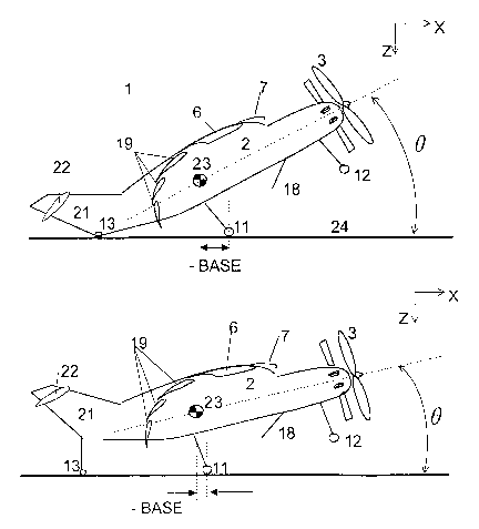
coordination and
enhanced effort by the pilot. The mechanisms required for pivoting large
components of the
160 aircraft are heavy and thus inefficient. Greater disturbances are
experienced during transitional
flight between vertical flight and horizontal flight with the use of hinged or
rotating wings.
G - Attitude Control by aerodynamic surfaces
Attitude control during hover flight is achieved in the present invention by
use of aerodynamic
surfaces 8, 15, 16 which are affected by the PGA 4. The invention, therefore,
does not require
165 auxiliary engines or propellers, which would only increase the weight,
cost, and complexity and
reduce the ease of control.
CA 02551027 2005-04-04
WO 2004/033295 PCT/EP2002/011386
H - No redirected exhaust or airflow through ducts or canals
The redirection of exhaust or airflow, present in many prior art, increases
the complexity of the
aircraft. Thus, the weight and the cost of manufacturing, maintenance and use
all increase.
170 Also, the control of such ducts requires very good coordination and
enhanced effort by the pilot.
The present invention uses a PGA 4, created over the main wing to generate
lift, thus no such
canals are necessary.
I - Stable nose-up fake-off and landing (NUTOL) position
The vertical take off and landing of an aircraft according to the present
invention is done by use of
175 a stable NUTOL (nose-up take-off and landing) position in which the entire
aircraft is tilted at a
pitch angle B; stable due to the positioning of the center of gravity 23. The
NUTOL position is
required to help create vertical flight, but is not excessive and thus not
uncomfortable for crew or
passengers.
J - High Drag Devices
180 The use of high drag devices 7, 18, 19 improves the vertical take off
capability as it acts against
the forward thrust force. With high drag devices, the aircraft can take off
with less NUTOL pitch
angle B than a similar VTOL aircraft without such devices.
K - Wing-tip configuration
The present invention discloses a wing-tip arrangement 17, 27, 28 such that
there is an
185 aerodynamic surface that is not exposed to the affects from the generated
airflow. This enables
damping and stability during steady horizontal flight. A multitude of
advantages also result due to
the combination of winglet 28, tip tank 17 and endplate 27, including
increasing the efficiency of
the PGA, enhancing the moment of inertia in the roll axis, minimizing the
unwanted fuel surge in
the y-direction, optimizing a stabilizing fuel surge in the x-direction,
alleviating the wing bending
190 moment, decreasing internal loads, complying with aviation certification
rules regarding the
placement of the fuel tanks, reinstating coordinated flight, and acting as a
housing for the main
undercarriage 11.
CA 02551027 2005-04-04
WO 2004/033295 PCT/EP2002/011386
Table 1: Related Patents,
X' indicates fhat the present invention has made an improvement on the
specified patent in the area
195 corresponding to fhe letter code.
Patent A B C D E F G H I J K
DE2433951 X X X X X
A
DE 42 37 X X X X X X
873 A1
DE4405975A X X X X X X X X X
US1890059 X X X X X
A
US 2974899 X X X X X X
A
US 3966142 X X X X X X
A
US 3995794 X X X X X X X X
A
US 4928907 X X X X X X X X X
A
US 5056737 X X X X
A
US 5098034 X X X X X X X X
A
US 5395073 X X X X X X X X
A
US 5407150 X X X X X X X X
A
WO 01!62591 X X X X X X X
A1
CH 0100109
BeII/Boeing X X X X X X X
"V22"
British Aerospace X X X X X X X
LETTER CODE of improving features of the present invention over existing
patents:
A Single propeller
B Inertial torque avoidance
C Stator for torque compensation
200 D Fixed thrust source
E Full load on main wing
F Fixed wing
G Attitude control by aerodynamic surfaces
H No redirected exhaust or airflow through
ducts or canals
205 I Stable nose-up take-off and landing (NUTOL)
position
J High drag devices
K Wing-tip configuration
CA 02551027 2005-04-04
WO 2004/033295 PCT/EP2002/011386
8
5-00 Brief description of the drawings:
Figure 1 shows an aircraft according to the invention with the key features
identified, in a
210 side view
Figure 2 shows an aircraft according to the invention in a top view
Figure 3 shows an aircraft according to the invention in a front view:
Figure 4 shows the creation of the PGA (Propeller Generated Airflow) over the
main wing
Figure 5 shows a cross section of the main wing of the aircraft according to
the invention
215 Figure 6 shows a vector diagram explaining the summation of the forces
acting on the
aircraft without drag (a) and with drag (b)
Figure 7 shows the hoisted tail, and the carry through area for the flaps
Figure 8 shows an aircraft in a stable CHTOL (conventional horizontal take-off
and landing)
position
220 Figure 9 shows an aircraft in two stable NUTOL (nose-up take-off and
landing) positions
Figure 10 shows a diagram explaining the need of a counter torque.
Figure 11 demonstrates the effect of the stator in developing counter torque
by illustrating a
cross-section view (a) and a front view of the stator (b)
Figure 12 shows the ventilate spoiler
225 Figure 13 shows a ducted propeller with an outlet nozzle shaped to deflect
the PGA
Figure 14 shows the ineffective PGA regions
Figure 15 shows an aircraft according to the present invention, with the
propeller mounted in
an alternative way.
Figure 16 demonstrates the different lift created due to the left and right
wings having
230 different angles of incidence
Figure 17 shows an aircraft according to the invention, in a ultra-light
configuration with
alternative landing gear.
Figure 18 shows the nose of the aircraft, depicting the non-ducted propeller
and stator, and
the propeller and stator blade cross-sections at the respective radial
position.
235 Figure 19 shows the nose of the aircraft, depicting the ducted propeller
and stator and the
propeller and stator blade cross-sections at the respective radial position.
CA 02551027 2005-04-04
WO 2004/033295 PCT/EP2002/011386
6-00 General Description:
Figures 1, 2 and 3, show the side, top and front views, respectively, of a
preferred embodiment of
an aircraft 1 according to the invention. The key features are identified on
these figures.
240 An aircraft according to the invention is similar to a single engine
conventional aircraft, comprising
a fuselage 2, a main wing 6 fixed to the fuselage 2, and a single constant
speed propeller 3. The
aircraft 1 is capable of vertical take-off and landing, as well as high speed
horizontal flight.
6.1 Propeller Generated Airflow (PGA) and Resulting Lift
Flight (including take off and landing) of an aircraft 1 according to the
invention is achieved by a
245 PGA (propeller generated airflow) 4 over the main wing 6 created by a
propeller positioned in front
of the main wing 6. Figure 4 demonstrates how the PGA 4 over the main wing 6
generates lift.
Propeller
According to the invention, the propeller consists of a constant speed
propeller.
In a preferred embodiment, the propeller 3 of an aircraft 1 according to the
invention is mounted in
250 the nose of the fuselage 2.
Further, the propeller 3 could comprise a duct 31, shown in figure 13, shaped
to deflect the
otherwise useless direction of airflow 33 in an effective direction of airflow
36, the effective
direction 36 being in the path of the aerodynamic surfaces, illustrated in
figure 14. A ducted
propeller would, however, be heavier and cause more drag at high speeds.
255 Another, rather important, redirection of the propeller airflow is
described in section 6.5 Torque
Compensation, Stator.
Alternatively, the duct 31 could rotate with the propeller blades, thereby
having the blades acting
as spokes and the duct a rotating rim. This arrangement reduces the losses at
the blade tips of a
propeller 3, and provides a larger, more effective thrust. Again, however, the
rotating rim would be
260 heavier, and it could also impose problems concerning centrifugal forces
acting on the rim.
In an alternative embodiment, the propeller could be mounted above the
fuselage 2, but still
forward of the main wing. Figure 15 shows an aircraft according to the
invention, with the propeller
3 being mounted to a protrusion 25 extending forward from the central upper
part of the fuselage
2.
265 Wing Unit
Vertical flight requires enhanced lift. To enhance the lift, the main wing 6
is equipped with leading
edge and trailing edge high lift devices, also subjected to the PGA 4.
CA 02551027 2005-04-04
WO 2004/033295 PCT/EP2002/011386
Trailing Edge
In a preferred embodiment, the main wing 6 has multi-Fowler type of flaps 19a,
19b, 19c
270 arranged in the PGA 4, shown in figure 5.
Figure 7 shows the fuselage 2 in a preferred arrangement so that it extends
only to the aft of
the main wing 6, at which point the tail is attached by hoists. With this
arrangement, the
Fowler flaps 19 can be made with a carry through box for the main spars of
each flap. The
flaps are therefore fu(I wingspan flaps, thereby enhancing the structural
integrity and ease of
275 controls.
In an alternate embodiment, the main wing 6 could be equipped with Handley
page type of
flaps.
Leading Edae
In a preferred embodiment, the main wing 6 is equipped with leading edge
devices such as
280 slats 7 to enhance the lift and to compensate the wing torsion moment
about the y-axis.
In an alternate embodiment, the main wing 6 could be equipped with nose flaps,
or Krueger
flaps at the leading edge.
6.2 Reducing Forward motion
Conventional Horizontal Take-off and Landing Position (CHTOL)
285 Figure 8 shows an aircraft 1 according to the invention, standing in a
stable CHTOL (conventional
horizontal take-off and landing) position on main gear 11 and on a nose gear
wheel 12. In this
position, when the PGA 4 is applied an aircraft according to the invention
will take-off in a
conventional horizontal manner ((.e. with forward motion). An aircraft 1
according to the invention
is also capable of a conventional horizontal landing.
290 In order to achieve solely vertical flight, the forward motion due to the
thrust, T, from the propeller
must be reduced to zero.
6.2.1 Nose-up Take-off and Landing (NUTOL) Position
To reduce the forward motion, an aircraft 1 according to the invention can
tilt into a stable
NUTOL (nose-up take-off and landing) position. In figure 9 two NUTOL pitch
angles B are
295 illustrated. At a certain NUTOL pitch angle B, the horizontal component of
the applied thrust T
is completely balanced by the horizontal component of the lift L, illustrated
in figure 6a, thus
enabling solely vertical flight.
CA 02551027 2005-04-04
WO 2004/033295 PCT/EP2002/011386
11
The NUTOL position is used for the vertical take-off and landing of an
aircraft 1 according to
the invention. Figure 9 shows an aircraft 1 according to the invention
standing in a stable.
300 NUTOL position on the main gear wheel 11 and on a tail support 13, the
tail support 13 being
aft of the main gear wheel 11.
A key feature of the invention is that the whole aircraft 1 is tilted, and not
just a single
component such as the wings or engine.
6.2.2 High Lift and Drag Devices
305 To further decrease the forward motion without requiring large angles of
NUTOL pitch angle ~,
an aircraft 1 according to the invention comprises high drag devices.
In a preferred embodiment, the trailing edge flaps 19 arranged in the PGA 4
are deflected
downward and extended backwards to an extreme during vertical flight such that
they
generate high drag.
310 In a preferred embodiment, the leading edge devices 7 for high lift extend
forward, but not as
far downward as conventionally used. The downward extension is used on
conventional
aircraft to reduce drag during take-off, but the aircraft 1 according to the
invention does not
require drag minimization during take-off.
In a preferred embodiment, an aircraft 1 according to the invention is further
equipped with a
315 retractable fuselage spoiler 18 which generates high drag as well as
contributing to the lift.
6.3 Vector Diagram Explanation of Vertical Flight:
To achieve vertical flight, the summation of the forces produced on the
aircraft 1 must result in a
resultant force R which is vertical (no horizontal component) acting on the
center of gravity 23 of
the aircraft 1.
320 Figure 5 shows an aircraft 1 according to the invention during vertical
flight, in a NUTOL position.
The propeller airflow 4 over the main wing 6, Fowler flaps 19, leading edge
slat 7, and fuselage
spoiler 18 create lifting forces LW, LF, L~ and LS on each component
respectively in an oblique
rearward direction. The components in the airflow also cause drag, the
significant drag being
caused by the Fowler flaps 19, DF and the fuselage spoiler 18, DS.
325 Figure 6b represents the summation of the forces acting on the aircraft 1
in vertical flight. The
forward horizontal component of the Thrust T is balanced by the backward
horizontal components
of the lift L and drag D forces. This results in no horizontal forces on the
aircraft 1, therefore no
horizontal movement. The vertical component of the thrust T and the lift
forces L combine to
created an upward force on the aircraft 1 that is only slightly diminished by
the vertical component
330 of the drag forces D. Altogether, the forces acting on the aircraft 1 will
produce the required
CA 02551027 2005-04-04
WO 2004/033295 PCT/EP2002/011386
12
vertical resultant force R. If the resultant force R acting on the center of
gravity 23 is greater than
the force of gravity G, the aircraft 1 will lift vertically. If the resultant
force R is less Than the force
of gravity G, the aircraft 1 will descend vertically.
It is clear from figure 6b that the NUTOL position of the aircraft 1,
demonstrated by the angle 8
335 from the horizontal plane, enables vertical flight by producing a lift
component that counters the
forward thrust applied. It is also clear from figures 6a and 6b that the
increased drag is of
advantage for the vertical take-off of the aircraft 1, since this allows the
NUTOL pitch angle B to be
reduced. Figure 6a represents the vector summation of an aircraft without the
high drag. The
angle B from the horizontal plane needed in order to obtain no resultant
horizontal forces without
340 the high drag is very large therefore it would be uncomfortable for
passengers and pilots, and
potentially less stable.
6.4 Vertical Climb and Descent
As described by the vector diagram, vertical climb of an aircraft 1 according
to the invention is
achieved by generating a resultant vertical force R that is greater than the
force of gravity G. In
345 order to increase this resultant force R, and thus climb vertically, the
thrust T of the propeller 3
must be increased. The thrust T is used to create the lift L and drag D
forces, therefore these
forces are also increased when the thrust is increased. The magnitude of the
vertical resultant
force R is therefore increased without a significant divergence from the
vertical path (i.e. the
horizontal forces still balance so there will be minimal movement
horizontally). Similarly, vertical
350 descent of an aircraft 1 according to the invention occurs when the
resultant vertical force R is less
than the force of gravity G and is accomplish by decreasing the thrust T.
6.5 Torque compensation
Inertial propeller torque is caused by acceleration of the rpm necessary for
power change.
Preferably, the propeller 3 is a constant speed propeller which is state of
the art in many propeller
355 aircraft, and eliminates the resultant inertia and acceleration related
torque on the aircraft 1 that
would otherwise be caused by changes in power by changing the propeller rpm.
There is also an aerodynamic propeller torque: the aircraft 1 experiences a
tendency to roll in a
direction opposite to the rotating direction of the single propeller 3 due to
propeller drag and the
driving engine torque z. Figure 10 illustrates this rotation of the propeller
3 and the corresponding
360 engine torque z. It is proposed in the present invention to generate a
counter-torque
aerodynamically in order to compensate this aerodynamic propeller torque.
Aerodynamic Torque Compensation is a means of roll control that governs the
specific roll caused
by the resultant engine torque i. The features used for roll control can also
be used to supplement
the aerodynamic torque compensation means.
CA 02551027 2005-04-04
WO 2004/033295 PCT/EP2002/011386
13
365 The resultant engine torque a is proportional to the thrust T produced by
the propeller 3, it is
therefore essential to develop an aerodynamic torque compensation that is also
related to the
thrust T produced, thereby eliminated problems of over-compensation or under-
compensation.
Stator
In a preferred embodiment an aircraft 1 according to the invention comprises a
stator 29 for
370 aerodynamic torque compensation. The PGA 4 acts on each stator blade,
creating small induced
forces, shown in figure 11. The small induced forces from each stator blade
combine to create a
counter torque in opposite direction to the torque of the engine z , shown in
the front view of figure
11.
The stator 29 is positioned a small distance behind the propeller but far
enough so as to keep
375 siren effect to a minimum, this distance is typically one propeller blade
chord length.
The stator 29 is a very beneficial means of aerodynamic torque compensation as
the counter
torque it creates is dependent on the airflow generated by the propeller 3. At
higher power, the
torque created by the propeller is greater, but the PGA and the angular
component of the PGA are
both increased. The increased speed and angular component of the PGA will
increase the
380 effectiveness of the stator as an aerodynamic torque compensation means
since the induced
forces created on each blade will be increased. The stator effectiveness will
therefore also
decrease appropriately with a decrease in power (and thus decrease in engine
torque z ). If the
engine torque ceased suddenly due to engine failure, the only airflow over the
stator blades is the
axial ambient airflow, thus the stator blades would have little or no effect.
385 The stator consists of at least 3 blades, preferably in the order of 12
blades as multiple blades
create a more uniform airflow thereby increasing the effectiveness of the PGA
4. The multitude of
blades and close position of the stator 29 to the propeller 3 ensures that the
stator 29 will not
create an adverse lift effect on the main wing 6. The length of the blades
would be between 0.4
and 1.5 times the length of the propeller blades.
390 Figures 18 and 19 illustrate a possible arrangement of the non-ducted
propeller and stator, and of
the ducted propeller and stator, respectively, depicting a preferable relative
diameter and position
of the stator. The twist, of both the propeller and stator blades, is a
function of radial position, and
is illustrated by the cross-sectional views 26, 37 in figures 18 and 19. The
twist of the stator blade
is such so as create the required counter torque generated through profile
lift (induced forces).
395 The twist is designed such that a fairly constant angle of attack between
6 and 8 degrees is
maintained at all radial positions. Large angles of attack and corresponding
stall is to be avoided
in all conditions. The airflow dictating the angle of attack of the stator
blades is a function of the
design and operating conditions of the propeller working in front of the
stator.
CA 02551027 2005-04-04
WO 2004/033295 PCT/EP2002/011386
14
The stator blades may further comprise trailing edge trim flaps, respectively,
in order to account for
400 variations in the angular component of the PGA 4. These trim flaps could
further be throttle
actuated.
Angle of Incidence
In an alternate embodiment, an aircraft 1 according to the invention has
different fixed angles of
incidence, zRW and z~W of the left and right main wing 6, respectively, shown
in figure 16. The
405 different angles of incidence z result in different lift capabilities. The
wing with the larger angle of
incidence z will produce more lift and thus create a roll moment about the x-
axis, countering the
induced roll due to the engine torque z .
The required difference in angle of incidence of the main wing 6 is dependent
on the speed of the
airflow over the wings. During steady horizontal flight, the airflow is faster
than during hover flight
410 due to a combination of ambient airflow and PGA 4, thus a smaller
difference in the incidence
angle z is required. In the alternate embodiment, an aircraft 1 according to
the invention has
different angles of incidence configured for steady flight in addition to a
leading edge device 7 That
is further extended on one side of the wings during hover flight to account
for the change in airflow
by inducing a greater lift on this side. However, the difference in the
incidence angle z is present
415 whether the engine is powered or not, thus there could be some undesired
roll effects if the power
fails during flight.
Size and Profile of W ings
In an alternate embodiment, the counter-torque may be generated by different
size of the main
wing 6, andlor by different profile effectiveness of the main wing 6 on the
left and the right side of
420 the aircraft 1. If the wings 6 have different size or effectiveness in
order to compensate for the
torque, unwanted roll maneuver will be caused during pitch maneuver. Again,
there could be
some undesired roll effects if the power fails during flight:
Weighted Wina
In a further embodiment, the counter-torque may be generated by a static
weight on right wing for
425 a clockwise rotating engine, or the left wing for a counterclockwise
rotating engine. The static
weight would create a counter torque that is not variable, and thus would
cause undesired roll
moments at different power settings, or no power.
Trim Flap
For the preceding further embodiments, the torque compensating means create
some amount of
430 undesired roll at different power settings. Therefore, in an further
embodiment, a trim flap, is
installed on the winglet 28 which could further be mechanically throttle
actuated.
CA 02551027 2005-04-04
WO 2004/033295 PCT/EP2002/011386
6.6 Attitude Control
Aerodynamic torque compensation acts on the roll axis (one of the 3 attitude
axes) of the aircraft,
thus it is a form of roll control. The features used for roll control can also
be used to supplement
435 the aerodynamic torque compensation means.
The aircraft 1 requires a well tuned, but simple control surface for
controlling the three degrees of
rotational freedom; roll, pitch and yaw, as does any other helicopter or
aircraft. If excessive power
were applied to a conventional aircraft with its flaps fully extended, it may
achieve a small vertical
lift off, but it would be unstable in roll, pitch and yaw. The roll control
surfaces iri conventional
440 aircraft would be useless without significant forward airspeed since they
are hardly exposed to any
airflow. The rudder and elevators for yaw and pitch control of conventional
aircraft are often
exposed to some propeller flow, but they are not sized or positioned to handle
vertical flight. For
this reason, an aircraft 1 according to the invention has similar control
surfaces as conventional
aircraft, but they positioned primarily within the PGA 4, and are sized for
vertical flight.
445 Roll Control
According to a preferred embodiment, the aircraft 1 consists of ventilated
spoilers 8 on the main
wing 6. The spoilers are positioned on the edge of the PGA 4, where they are
effective roll control
devices in both vertical and horizontal flight. Figures 2 and 3 illustrate the
positioning of the
spoilers where the pressure gradient above and below the main wing 6 is very
high. Ventilated
450 spoilers, illustrated in figure 12, are thus very effective in this area,
as the ventilation affects the
pressure gradient and thereby the lift created by the wing.
Alternatively, the ventilated spoilers could be positioned completely within
the PGA 4.
In an alternative embodiment, the main wing 6 could consist of ailerons or non-
ventilated spoilers
positioned within the PGA 4 for roll control. Ailerons are non-preferred as
they could interfere with
455 the Fowler flaps.
In an alternative embodiment, the leading edge devices 7, positioned in the
PGA 4, could be used
for roll control.
Pitch Control
In a preferred embodiment pitch control of the aircraft 1 according to the
invention is achieved
460 through conventional elevator 15 control surfaces being mounted within the
PGA 4.
Yaw Control
Directional control of the aircraft is achieved through rudder control
surfaces 16 at the tail being
mounted in the PGA 4. Alternatively, nose mounted controls, i. e. forward of
the center of gravity
CA 02551027 2005-04-04
WO 2004/033295 PCT/EP2002/011386
16
23, in the PGA 4 can be used. However, special care must be taken that these
surfaces are free to
465 weather vane, otherwise an unfavorable destabilizing effect at forward
airspeeds is generated.
6.7 Ground Effect Compensation:
As the aircraft 1 lifts off, and the gap between the main wing flaps and the
ground widens causing
a slight pressure loss. This pressure loss behind the center of gravity 23
creates a moment about
the y-axis, causing the aircraft 1 to pitch nose-up. Pitch moments change
rapidly leaving and
470 entering a ground effect. Therefore, in a preferred embodiment, the
fuselage spoiler 18 is mounted
underneath the fuselage 2 forward of the center of gravity 23 of an aircraft 1
according to the
invention. A fuselage spoiler 18 of this type experiences a similar pressure
loss during the initial
climb phase, but forward of the center of gravity 23. As both elements cause a
corresponding pitch
ground effect but with opposite levers with respect to center of gravity 23, a
climb-out, stable in
475 pitch can be achieved by using the fuselage spoiler 18. Further, the
fuselage spoiler 18 serves to
enhance the drag and the lift during take-off and landing, illustrated in
figures 5 and 6b.
6.8 Transitional Flight:
The method of transition from vertical to horizontal flight, and back, of an
aircraft 1 according to the
invention is done through the retraction of the high drag devices, such as the
Fowler Flaps 19, the
480 leading edge devices 7, and the fuselage spoiler 18. Because the aircraft
1 according to the
invention is propelled in all modes of flight by a single universal propeller
3, and because the
aircraft 1 is always flying on aerodynamic lift, there is no distinct
aerodynamic change during the
transitional flight. Major aerodynamic and flight dynamic changes during
transitional flight due to
transitions from rotor lifted to attached aerodynamic flow and stall phases
involved in these
485 processes have often lead to the failure of VTOL aircraft.
6.9 High Speed Horizontal Flight
The power required for vertical take-off implies that the engine of an
aircraft 1 according to the
invention will be very powerful, and thus enable high horizontal air speeds.
The respective power
requirement is similar to existing single engine high performance turbo-prop
aircraft. In addition, a
490 conventionally wide wing is not necessary and thus the wingspan can be
relatively small, which is
beneficial for high speed horizontal flight.
6.10 Over-Center position and Center of Gravity
The two stable positions of an aircraft 1 according to the invention
illustrated in figures 8 and 9
are a result of the position of the center of gravity 23 of the aircraft 1.
The center of gravity 23 is
495 along a center x-axis of the aircraft 1, in a positive base position (x-
direction distance from main
landing gear) between the nose gear wheel 12 and the main gear wheel 11, like
in a conventional
aircraft. It is so close to the main gear wheel 11, that a nose-up pitch of
the aircraft 1 results in a
CA 02551027 2005-04-04
WO 2004/033295 PCT/EP2002/011386
17
stable parking position on the main gear wheel 11 and the tail support 13 as
the base position
becomes negative.
500 In a preferred embodiment, the NUTOL position may be achieved by applying
a reverse thrust in
the horizontal position with the breaks applied to the main landing gear. The
center of gravity 23
rotates with the aircraft about the main landing gear 11 until the base
position shifts from positive
to negative. This process is referred to as over-center.
In a preferred embodiment, the tail support 13 comprises a bumper in order to
attenuate shocks
505 when landing the aircraft 1 in a NUTOL position.
In a preferred embodiment, the tail support 13 is of adjustable length in
order to take account of
the operational variation of the center of gravity 23 of the aircraft 1, or of
a non-horizontal ground
24, illustrated by the two different NUTOL positions in figure 9.
A tricycle gear is standard technology, but not the NUTOL position of the
present application
510 shown in figure 9. Actually, it would be an indication of extreme danger
to an airplane pilot if a
conventionally designed aircraft inadvertently tilted to the NUTOL position
before take-off, since it
indicates a too far aft loading of the conventional aircraft with resulting
instability and
uncontrollability in the air.
In an alternative embodiment, an aircraft 1 according to the invention only
has one stable position,
515 being the NUTOL position. The aircraft 1 according to this alternative is
illustrated in figure 17.
This alternative would not require the over-center means of achieving the
NUTOL position, or a tail
support 13. The main landing gear 11 is located near the tail, far aft of the
center of gravity 23. In
order to obtain more stability on the ground, there are 2 nose wheels 30
instead of one. The
forward nose wheels 30 are trailing, whereas as the rear main gear 11 are
fixed, thus directional
520 stability during take-off and landing is improved. Conventional horizontal
take-off and landing is
still possible in this alternative embodiment with a slightly retracted
configuration of the high lift and
drag devices.
6,11 Wing-tip Configuration
In a preferred embodiment, an aircraft 1 according to the invention comprises
a wing-tip
525 configuration (a combination of a end plate 27, winglet 28, and fuel tank
17) that has a multitude of
effects:
~ enhances the moment of inertia about the roll axis,
~ minimizes the unwanted fuel surge in the y-direction,
~ creates a stabilizing fuel surge in the x-direction,
530 ~ alleviates the wing bending moment, decreases internal loads,
~ complies with aviation certification rules regarding fuel tanks,
~ reinstates coordinated flight,
CA 02551027 2005-04-04
WO 2004/033295 PCT/EP2002/011386
18
~ acts as a housing for the main undercarriage 11.
Endplates
535 According to the preferred embodiment, endplates 27 extend downward from
the tips of the main
wing 6. The endplates 27 act as a means of containing the PGA 4 and pressure
gradient below
the main wing 6, thereby enhancing the performance of the flaps. The endplates
27 also act as a
guidance for the flap system 19, thereby decreasing the internal loads. The
endplates 27 could
further be used as a housing for the main undercarriage 11.
540 Windlets
The presence of the endplates 27 destabilizes the aircraft in roll. The
aircraft 1 is therefore
provided with winglets 28 which extend outwards and upwards from the tips of
the main wing 6 to
stabilize the aircraft 1. The winglets 28 act in conjunction with the
endplates 27 to reinstate the
stable benign roll moment thereby achieving coordinated flight.
545 The winglets 28 further serve to protect the inner portion of the wing
from potential lightning strike.
Fuel Tanks
Any aircraft is subject to instability due to fuel surge in the y-direction.
Therefore, in a preferred
embodiment, the aircraft 1 is comprised of fuel tanks 17 of cylindrical shape,
with the longitudinal
axis in the x-direction, thereby minimizing the fuel surge in the y-direction.
550 The aircraft 1 will have its smallest moment of inertia about the roll
axis, and may, to be more
conveniently flown by the pilot, require an enhancement of said moment of
inertia. Therefore,
according to a preferred embodiment of the invention, the fuel tanks 17 are
mounted at the
intersection of the winglets 28 and the endplates 27, to enhance roll inertia.
In this position, the fuel tanks 17 are protected by the winglets 28 from
lightning strike, and thus
555 the aircraft 1 complies with new aviation certification rules.
The x-direction fuel surge in this shape tank 17 is beneficial since when
switching from the CHTOL
position to the NUTOL position, the contents of the fuel tanks 17 move toward
the tail of the
aircraft 1, further stabilizing the aircraft 1 in the new posifion. The same
stabilizing effect occur
when returning to the CHTOL position.
560 The tip tanks 17 further serve to alleviate the wing bending moment about
the x-axis.
6.12 Longitudinal Weight Trims
In accordance with a preferred embodiment of the invention, the aircraft 1
comprises a trim system
for keeping the center of gravity in the longitudinal (x-direction) within
narrow limits. Preferably,
CA 02551027 2005-04-04
WO 2004/033295 PCT/EP2002/011386
19
such trim systems may comprise simple compartments in the nose and the tail
that are loaded
565 with shot bags before take-off, in accordance with aircraft loading.
Alternatively, the trim system
may comprise aft and nose tanks, and means for pumping a liquid to and from
said tanks.
The different features mentioned in the description are examples of how the
invention may be
implemented. The invention is only limited by the appended claims.
CA 02551027 2005-04-04
WO 2004/033295 PCT/EP2002/011386
570 List of features with corresponding reference signs:
1 aircraft R Resultant Force
2 fuselage G Force due to gravity
3 thrust generating source T Thrust
4 propeller generated airflowL Total Lift ,
(PGA)
5 nose of the aircraft D Total Drag
6 main wing LW Lift from Wing
7 leading edge slat on the LS Lift from fuselage
main wing spoiler
10 canard wing LF Lift from Flaps
11 main gear wheel L~ Lift from leading
edge device
12 nose gear wheel DF Drag from Flaps
13 tail support DS Drag from fuselage
spoiler
14 engine LW Left Wing
15 elevator RW Right Wing
16 rudder LAWLift on Left Wing
17 tip tank LRWLift on Right Wing
18 fuselage spoiler aRwangle of incidence
of right wing
19 multi-Fowler type of flap t~Wangle of incidence
of left wing
20 trim flap on the canard z resultant engine
wing torque
21 vertical sfabilizer a angle of attack
of stator blade
22 horizontal stabilizer B angle of NUTOL position
23 center of gravity a~ propeller rotation
24 ground N induced force on
stator blades
protrusion
26 cross section of propeller
at radial
position
27 endplate
28 winglet
29 stator
forward trailing landing
gear
31 duct
32 duct nozzle
33 ineffective airflow region
34 hoists for attaching tail
carry through area for
flap spars
36 effective airflow region
37 cross section of stator
at radial position