Language selection

Search

Patent 2551108 Summary

Third-party information liability

Some of the information on this Web page has been provided by external sources. The Government of Canada is not responsible for the accuracy, reliability or currency of the information supplied by external sources. Users wishing to rely upon this information should consult directly with the source of the information. Content provided by external sources is not subject to official languages, privacy and accessibility requirements.

Claims and Abstract availability

Any discrepancies in the text and image of the Claims and Abstract are due to differing posting times. Text of the Claims and Abstract are posted:

  • At the time the application is open to public inspection;
  • At the time of issue of the patent (grant).
(12) Patent: (11) CA 2551108
(54) English Title: EXIT DEVICE WITH LIGHTED TOUCHPAD
(54) French Title: DISPOSITIF DE SORTIE COMPRENANT UNE TOUCHE A EFFLEUREMENT ECLAIREE
Status: Granted and Issued
Bibliographic Data
(51) International Patent Classification (IPC):
  • G09F 13/04 (2006.01)
(72) Inventors :
  • MOLOKOTOS, THANASIS (United States of America)
  • PICARD, DANIEL J. (United States of America)
(73) Owners :
  • SARGENT MANUFACTURING COMPANY
(71) Applicants :
  • SARGENT MANUFACTURING COMPANY (United States of America)
(74) Agent: SMART & BIGGAR LP
(74) Associate agent:
(45) Issued: 2010-11-23
(86) PCT Filing Date: 2004-12-08
(87) Open to Public Inspection: 2005-07-21
Examination requested: 2007-11-29
Availability of licence: N/A
Dedicated to the Public: N/A
(25) Language of filing: English

Patent Cooperation Treaty (PCT): Yes
(86) PCT Filing Number: PCT/US2004/040987
(87) International Publication Number: US2004040987
(85) National Entry: 2006-06-21

(30) Application Priority Data:
Application No. Country/Territory Date
10/748,622 (United States of America) 2003-12-29

Abstracts

English Abstract


An exit device includes an electroluminescent exit sign assembly, preferably
mounted on a push rail actuator of the exit device. An electroluminescent
illuminator, an opaque material and a transparent protective cover form the
electroluminescent sign assembly. The push rail actuator operates a latch
mechanism and opens an associated exit door when pressure is applied. An
inverter may be located within the exit device to power the electroluminescent
illuminator with an AC or voltage. The electroluminescent sign assembly is
preferably removable for repair or replacement without removing the exit
device from the exit door and is located within a surface cavity in an
electrically insulating touchpad on the exit device actuator. Additional
transparent nonconductive material surrounds the electroluminescent material
to provide further electrical insulation.


French Abstract

L'invention concerne un dispositif de sortie comprenant un ensemble de signe de sortie électroluminescent, de préférence monté sur une commande à rail poussoir du dispositif de sortie. Un illuminateur électroluminescent, un matériau opaque et un élément couvrant protecteur transparent constituent l'ensemble de signe électroluminescent. La commande à rail poussoir fait fonctionner un mécanisme de verrouillage et ouvre une porte de sortie associée quand de la pression est appliquée. Un inverseur peut être placé dans le dispositif de sortie, de manière à alimenter l'illuminateur électroluminescent au moyen de CA ou de tension. L'ensemble de signe électroluminescent est, de préférence, amovible aux fins de réparation ou de remplacement, sans retrait du dispositif de sortie de la porte de sortie, et il est situé dans une cavité de surface dans une touche à effleurement électriquement isolante sur la commande du dispositif de sortie. Un matériau non conducteur transparent supplémentaire entoure le matériau électroluminescent, de manière à conférer une isolation électrique supplémentaire.

Claims

Note: Claims are shown in the official language in which they were submitted.

What is claimed is:
1. An illuminated exit device comprising:
a door latch mechanism;
a base for attachment to a surface of a door;
an actuator movably mounted relative to the base and connected to operate
the door latch mechanism when pressure is applied to the actuator by a
person desiring to operate the exit device;
a planar electroluminescent illuminator including electrical wiring extending
through the exit device for connection to a source of electrical power;
a planar sign including opaque portions for blocking illumination from the
electroluminescent illuminator, the sign being mounted in front of the
electroluminescent illuminator;
a transparent protective cover mounted in front of the sign, the illuminator,
sign and covering plate forming a sign assembly visibly mounted on the exit
device; and
a touchpad mounted on the actuator, the touchpad including a surface cavity
in a surface thereof and the surface cavity including a plurality of openings,
the transparent cover including a plurality of tabs, whereby the sign assembly
is held in the surface cavity by engagement between the tabs of the
transparent cover and the openings in the surface cavity.
2. The illuminated exit device according to claim 1 wherein the actuator
comprises an elongated push bar.
3. The illuminated exit device according to claim 1 wherein the sign assembly
is
mounted on the actuator and pressure applied to the sign assembly will
operate the exit device.

4. The illuminated exit device according to claim 1 further including a
touchpad
mounted on the actuator, and wherein the sign assembly is mounted on the
touchpad.
5. The illuminated exit device according to claim 4 wherein the touchpad
includes a surface cavity in a surface thereof and the sign assembly is
mounted in the surface cavity with the transparent protective cover
positioned flush with the surface of the touchpad.
6. The illuminated exit device according to claim 4 wherein the touchpad is
formed of an electrically insulating material providing an electrically
insulating barrier between the electroluminescent illuminator and other parts
of the exit device.
7. The illuminated exit device according to claim 6 wherein the touchpad is
formed of plastic.
8. The illuminated exit device according to claim 6 wherein the
electroluminescent illuminator is encased in a transparent plastic comprising
an additional electrical insulator to provide double electrical insulation
between the electroluminescent illuminator and other parts of the exit device.
9. The illuminated exit device according to claim 1 wherein the planar sign
comprises an opaque film adhesively attached to the transparent protective
cover.
10. The illuminated exit device according to claim 9 wherein the planar sign
comprises an opaque paint.

11. The illuminated exit device according to claim 1 wherein the sign includes
letters forming one or more words.
12. The illuminated exit device according to claim 11 wherein the sign
includes
letters forming the word "EXIT".
13. The illuminated exit device according to claim 1 wherein the
electroluminescent illuminator is encased in a transparent plastic comprising
an electrical insulator.
14. The illuminated exit device according to claim 1 wherein the inverter
provides
high voltage AC power to the electroluminescent illuminator from a low
voltage which is suitable for driving electromechanical locks and hardware.
15. The illuminated exit device according to claim 1 wherein the inverter
provides
high voltage AC power to the electroluminescent illuminator from a 24 volts
AC or DC power input to the inverter.
16. The illuminated exit device according to claim 1 wherein the inverter is
mounted in the base.
17. The illuminated exit device according to claim 1 wherein:
the base includes an opening facing towards the surface of the door on
which the base is to be attached; and
the electrical wiring is hidden from view within the exit device and extends
from the electroluminescent illuminator to the opening in the base.

18. The illuminated exit device according to claim 1 wherein the transparent
cover is removable without removal of the exit device from the door to
permit replacement or repair of the electroluminescent illuminator.
19. The illuminated exit device according to claim 1 further including an
inverter
for supplying power to the electroluminescent illuminator.
20. The illuminated exit device according to claim 19 wherein the inverter
operates to provide a high voltage AC power to the electroluminescent
illuminator from a low voltage input to the inverter, said low voltage set at
a
voltage level below the level which would pose a shock hazard to a human
user.

Description

Note: Descriptions are shown in the official language in which they were submitted.


CA 02551108 2006-06-21
WO 2005/066921 PCT/US2004/040987
1
DESCRIPTION
EXIT DEVICE WITH LIGHTED TOUCHPAD
Technical Field
The present invention relates to exit devices, of the type used to rapidly and
reliably open exit doors and allow people to exit public buildings in the
event of a
fire, panic situation or other emergency. More particularly, the present
invention
relates to electrically illuminated exit devices.
Description of Related Art
An "exit device" is a lock mechanism operated from the inside of an outward
swing door through the use of a crossbar, push bar or push rail actuator, that
is
designed to open an exit door, allowing exit without prior knowledge of how
the
lock operates, whenever a horizontal force is applied to the actuator. Exit
devices
are typically required by fire or building codes and are used in public
buildings
where many people may be gathered, to provide rapid, safe and easy egress in
case
of emergency.
Exit devices ensure that an exit door is free to operate from the inside of
the
locked area, yet they allow the exit door to remain locked to prevent
unauthorized
entry from the outside.
Although exit device's have been highly successful in performing the
function for which they were designed, deaths in public building fires
continue to
occur. Some deaths can be traced to the inability of those within the building
to
quickly identify all the building exit doors when smoke from the fire obscures
required exit signage. Such signage is typically located close to the ceiling
of
public rooms, which permits it to be seen over the heads of those within the
room.
However, this location is the first to become obscured when smoke and heated
air
from a fire rise to the ceiling in the room.
There remains a need to improve exit signage and to directly and rapidly
signal to the public the location of each exit door and the location of the
actuator
for each exit door, particularly in low light or smoke-obscured conditions
that
accompany a fire.
Conventional illumination devices, which might meet this need, such as
incandescent bulbs, are bulky, fragile, provide non-uniform illumination and
produce excessive heat, all of which makes them unsuitable for installation in
an
exit device. An exit device is subject to repeated impact as the door is
operated, so

CA 02551108 2006-06-21
WO 2005/066921 PCT/US2004/040987
-2-
any illuminator located therein must be extremely rugged. The illuminator must
not produce heat which could potentially burn a user touching metal components
of the exit device, or which might present a fire hazard when the exit device
is
installed on a wooden door. The illuminator must be long lasting to minimize
maintenance costs, yet it must reliably illuminate in an emergency situation.
Disclosure of Invention
Bearing in mind the problems and deficiencies of the prior art, it is
therefore
an object of the present invention to provide an exit device with an
integrated
illuminated sign assembly.
It is another object of the present invention to provide an exit device with
an
integrated illuminated sign assembly that is long lasting and impact
resistant.
A further object of the invention is to provide an exit device with an
integrated illuminated sign assembly that produces no heat and wherein the
illuminated sign may be located directly on the exit device push bar or
actuator.
The above and other objects, which will be apparent to those skilled in art,
are achieved in , the present invention which is directed to an illuminated
exit
device including a door latch mechanism, a base for attachment to a surface of
a
door, an actuator, a planar electroluminescent illuminator, a planar sign
including
opaque portions for blocking illumination from the electroluminescent
illuminator,
and a transparent protective cover mounted in front of the sign.
The illuminator, sign and covering plate form a sign assembly visibly
mounted on the exit device. The actuator is movably mounted relative to the
base
and is connected to operate the latch mechanism when pressure is applied to
thereto. The electroluminescent illuminator includes electrical wiring
extending
through the exit device for connection to a source of electrical power, either
directly or through an inverter. The sign is mounted between the
electroluminescent illuminator and the transparent cover.
The actuator may be a pushbar, push rail, push plate or other known type of
exit device actuator. The latch mechanism may be of the type illustrated or it
may
be a hidden or visible vertical rod design or other known latch mechanism
design,
which will be familiar to those of skill in this field.
The sign assembly is preferably mounted on the actuator such that pressure
applied directly to the illuminated sign assembly will operate the exit
device. The
sign assembly may be directly mounted on the actuator or it may be mounted on
a

CA 02551108 2006-06-21
WO 2005/066921 PCT/US2004/040987
-3-
touchpad mounted on the actuator. The touchpad may provide additional
electrical
insulation and may simplify removal, repair and replacement of the sign
assembly
and the components thereof.
The sign assembly is preferably mounted in a surface cavity in the touchpad
with the transparent protective cover positioned flush with the surface of the
touchpad. The electroluminescent illuminator is preferably encased in a
transparent plastic which cooperates with the insulation formed by the
touchpad to
provide double electrical insulation between the electroluminescent
illuminator
and other parts of the exit device that may be contacted by the public when
the exit
device is used. The sign preferably includes the word "EXIT" and/or other
verbage
in English or other languages, appearing one or more times thereon.
The optional integrated inverter provides a high voltage AC power to the
electroluminescent illuminator from a low voltage input to the inverter, the
low
voltage not presenting a shock hazard, and the high voltage being insulated
from
the other parts of the exit device. The low voltage for the inverter is
preferably also
a voltage suitable for driving electromechanical locks and hardware, such as
24
volts AC or DC. Most preferably the inverter is capable of operating from both
AC
and DC voltage.
The illuminated exit device is designed to permit removal of the transparent
cover and/or the touchpad to permit replacement or repair of the
electroluminescent illuminator.
Brief Description of the Drawings
The features of the invention believed to be novel and the elements
characteristic of the invention are set forth with particularity in the
appended
claims. The figures are for illustration purposes only and are not drawn to
scale.
The invention itself, however, both as to organization and method of
operation,
may best be understood by reference to the detailed description which follows
taken in conjunction with the accompanying drawings in which:
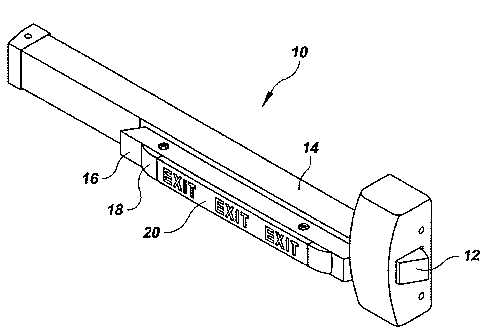
Fig. 1 is a perspective view of a fully assembled exit device according to the
present invention adapted for installation on a right hand reverse bevel exit
door.
Fig. 2 is a perspective view of an exit device for a left hand reverse bevel
exit
door according to the present invention, with the sign assembly shown in
exploded
view format. The exit device is shown mounted on a door and wiring, an
electric
hinge and an inverter are shown in phantom.

CA 02551108 2006-06-21
WO 2005/066921 PCT/US2004/040987
Models) for Carrying Out Invention
In describing the preferred embodiment of the present invention, reference
will be made herein to Figs. 1-2 of the drawings in which like numerals refer
to like
features of the invention.
Referring to Fig. 1, an illuminated exit device 10 includes a door latch
mechanism 12, a base 14 for attachment to a surface of a door, and an actuator
16
movably mounted relative to the base and connected to operate the latch
mechanism 12. When pressure is applied directly to the actuator 16, to the
touchpad 18 or to an integrated electroluminescent sign assembly 20, the latch
mechanism is operated to open the exit door.
Referring to Fig. 2, it can be seen that the actuator 16 is provided with a
touchpad 18 having a surface cavity 22 formed therein for receiving the sign
assembly 20. The sign assembly 20 is formed from a planar electroluminescent
illuminator 24, a planar sign 26 having opaque portions to form the readable
sign
and a transparent protective cover 28.
The electroluminescent illuminator includes an electroluminescent material
30 preferably encased in a transparent electrically insulating material 32.
The sign
26 may be a separate element or it may be a thin film adhesively attached to
and
integrated with the cover 28. Alternatively, it may be in the form of paint
applied
to the electroluminescent illuminator or the transparent cover. The opaque
portions
of the sign may form the lettering of the sign or the area around the
lettering.
The touchpad 18 is preferably constructed of an electrically insulating
plastic, which cooperates with the transparent coating 32 around the
electroluminescent material 30 to provide double electrical insulation between
the
electroluminescent illuminator and other components of the exit device.
The cover 28 includes multiple tabs 34 which engage corresponding
openings 36 in the surface cavity 22. Wiring 38 extends from the illuminator
30
through the touchpad 18, through an opening 40 in the actuator 16 to an
optional
inverter 42 located within the body of the exit device 14. Wiring 40 continues
through an opening 44 into the door and through an electric hinge 46 and into
the
wall where connection is made to a source of power. An "electric hinge" is a
commercially available product which allows electrical connections to be made
through the hinge line of an exit door

CA 02551108 2006-06-21
WO 2005/066921 PCT/US2004/040987
-5-
In the preferred design, the inverter 42 is powered with a low voltage AC or
DC voltage which is also suitable for powering electro-mechanical locks and
hardware. Alternatively, the inverter 42 may be omitted and a direct
connection to
a suitable power supply is provided.
The electroluminescent material 30 is typically provided with a 200 volt,
400 Hertz AC signal by the inverter 42. Connectors at 48 and 50 allow the
touchpad and sign assembly to be disconnected without the necessity of
removing
the exit device from the door. Connector 52 allows the exit device to be
connected
to wiring from the electric hinge 46.
While the present invention has been particularly described, in conjunction
with a specific preferred embodiment, it is evident that many alternatives,
modifications and variations will be apparent to those skilled in the art in
light of
the foregoing description. It is therefore contemplated that the appended
claims
will embrace any such alternatives, modifications and variations as falling
within
the true scope and spirit of the present invention.
Thus, having described the invention, what is claimed is:

Representative Drawing
A single figure which represents the drawing illustrating the invention.
Administrative Status

2024-08-01:As part of the Next Generation Patents (NGP) transition, the Canadian Patents Database (CPD) now contains a more detailed Event History, which replicates the Event Log of our new back-office solution.

Please note that "Inactive:" events refers to events no longer in use in our new back-office solution.

For a clearer understanding of the status of the application/patent presented on this page, the site Disclaimer , as well as the definitions for Patent , Event History , Maintenance Fee  and Payment History  should be consulted.

Event History

Description Date
Common Representative Appointed 2019-10-30
Change of Address or Method of Correspondence Request Received 2018-01-12
Grant by Issuance 2010-11-23
Inactive: Cover page published 2010-11-22
Inactive: Final fee received 2010-09-03
Pre-grant 2010-09-03
Notice of Allowance is Issued 2010-06-16
Letter Sent 2010-06-16
Notice of Allowance is Issued 2010-06-16
Inactive: Approved for allowance (AFA) 2010-06-01
Amendment Received - Voluntary Amendment 2009-12-23
Inactive: S.30(2) Rules - Examiner requisition 2009-06-25
Letter Sent 2008-02-08
Inactive: IPRP received 2008-02-06
Request for Examination Requirements Determined Compliant 2007-11-29
All Requirements for Examination Determined Compliant 2007-11-29
Request for Examination Received 2007-11-29
Inactive: Cover page published 2006-09-06
Inactive: Notice - National entry - No RFE 2006-08-30
Letter Sent 2006-08-30
Application Received - PCT 2006-07-31
National Entry Requirements Determined Compliant 2006-06-21
Application Published (Open to Public Inspection) 2005-07-21

Abandonment History

There is no abandonment history.

Maintenance Fee

The last payment was received on 2010-10-04

Note : If the full payment has not been received on or before the date indicated, a further fee may be required which may be one of the following

  • the reinstatement fee;
  • the late payment fee; or
  • additional fee to reverse deemed expiry.

Patent fees are adjusted on the 1st of January every year. The amounts above are the current amounts if received by December 31 of the current year.
Please refer to the CIPO Patent Fees web page to see all current fee amounts.

Owners on Record

Note: Records showing the ownership history in alphabetical order.

Current Owners on Record
SARGENT MANUFACTURING COMPANY
Past Owners on Record
DANIEL J. PICARD
THANASIS MOLOKOTOS
Past Owners that do not appear in the "Owners on Record" listing will appear in other documentation within the application.
Documents

To view selected files, please enter reCAPTCHA code :


To view images, click a link in the Document Description column. To download the documents, select one or more checkboxes in the first column and then click the "Download Selected in PDF format (Zip Archive)" or the "Download Selected as Single PDF" button.

List of published and non-published patent-specific documents on the CPD .

If you have any difficulty accessing content, you can call the Client Service Centre at 1-866-997-1936 or send them an e-mail at CIPO Client Service Centre.


Document
Description 
Date
(yyyy-mm-dd) 
Number of pages   Size of Image (KB) 
Claims 2006-06-20 3 121
Description 2006-06-20 5 262
Abstract 2006-06-20 2 68
Drawings 2006-06-20 2 32
Representative drawing 2006-06-20 1 8
Claims 2009-12-22 4 112
Representative drawing 2010-11-02 1 10
Reminder of maintenance fee due 2006-08-29 1 110
Notice of National Entry 2006-08-29 1 193
Courtesy - Certificate of registration (related document(s)) 2006-08-29 1 105
Acknowledgement of Request for Examination 2008-02-07 1 177
Commissioner's Notice - Application Found Allowable 2010-06-15 1 164
PCT 2006-06-20 3 91
Fees 2006-09-20 1 28
Fees 2007-09-12 1 29
PCT 2006-06-21 9 395
Fees 2008-09-18 1 35
Fees 2009-09-15 1 34
Correspondence 2010-09-02 1 36
Fees 2010-10-03 1 36