Note: Descriptions are shown in the official language in which they were submitted.
CA 02551283 2006-06-22
WO 2005/064117
PCT/EP2004/053675
- 1 -
METHOD OF DETERMINING A FLUID INFLOW PROFILE OF WELLBORE
BACKGROUND OF THE INVENTION
The invention relates to a method of determining a
fluid inflow profile along the length of a permeable
inflow region of an underground wellbore.
Temperature logs have been used for many years in the
oil and gas industry to obtain inflow and outflow
information of selected intervals. US patent 4,520,666
discloses a method of determining inflow into a well by
determining the temperature in the well along the length
of the inflow region by moving a logging sonde which is
equipped with a temperature sensor up and/or down through
the well inflow region.
More recently fiber optic Distributed Temperature
Sensing (DTS) systems have become available to obtain
temperature profiles along a well on a permanent basis.
International patent application WO 01/04581 discloses
the use of a fiber optic DTS sensor to determine the mass
flow rates of produced fluids in a wellbore.
The temperature profile in an oil and/or gas
production well is based on the difference between the
geothermal gradient along the well and the inflowing
fluids. In vertical or deviated wells a temperature
contrast develops if two or more zones at different
depths produce to the well. This temperature contrast is
a function of the reservoir depth, the geothermal
gradient and the thermal properties of the fluid and the
well (casing, cement).
CA 02551283 2006-06-22
WO 2005/064117
PCT/EP2004/053675
- 2 -
In a horizontal inflow region of an oil and/or gas
productions well there is no geothermal gradient along
the horizontal section. Differences can only be caused
either by cooling due to gas expansion, known as the
Joule Thompson effect, which occurs in gas reservoirs or
oil reservoirs where gas comes out of solution during
production, or when water is produced from a deeper
aquifer (potential higher temperature) or from a nearby
water injector (potential lower temperature).
International patent application WO 00/11317 and
US patent 6,497,279 disclose methods of monitoring
production in an oil production well by means of an
electrical heater cable and adjacent fiber optical DTS
sensor, wherein the wellbore is heated by the electrical
heater cable during production and the fluid flow is
determined from the temperature profile measured by the
fiber optical DTS sensor on the assumption that the fluid
flowing from the formation to the wellbore lowers the
temperature in the wellbore at the inflow locations.
US patent application US 2003/0140711 discloses a
method for monitoring the velocity of fluids in a well
wherein a point near the lower end of the well is cooled
during a well shut in and the upward velocity of the cold
spot is measured after restarting production by a fibre
optical temperature sensing cable that extends along the
length of the wellbore.
It is an object of the present invention to provide a
method for determining the inflow profile along at least
a substantial part of the length of a fluid inflow region
of a well in a more accurate manner than the known
methods.
It is a further object of the present invention to
provide a method for determining the inflow profile along
CA 02551283 2012-02-08
63293-4073
- 3 -
at least a substantial part of the length of a fluid
inflow region of a well, which can be configured to
provide information about the heat capacity and/or
composition of the fluid flowing from the formation into
the well at various points along the length of the inflow
region.
SUMMARY OF THE INVENTION
In accordance with the invention there is provided a
method of determining a fluid inflow profile along the
length of a permeable inflow region of an underground
wellbore, the method comprising the steps of:
- transferring heat into the permeable inflow region of
the wellbore during a well shut in period such that at
least a substantial part of the inflow region has a
temperature which is different from the temperature of
the surrounding formation;
- starting production of hydrocarbon fluids via said
permeable inflow region;
- measuring substantially simultaneously the
temperature of the fluids at various points along at
least part of the length of the inflow region; and
- determining at selected intervals of time after
production start up a temperature profile along at least
part of the length of the inflow region on the basis of
the thus measured temperatures;
characterised in that the method further comprises
determining a fluid inflow profile along the length of
said inflow region on the basis of a comparison of the
determined temperature profiles at selected intervals
after production start up, wherein at least a substantial
part of the permeable inflow region is heated during the
well shut-in period and wherein during an initial period
of time after starting production of hydrocarbons via
CA 02551283 2012-02-08
63293-4073
- 4 -
said permeable inflow region heating of the permeable
inflow region is continued and wherein during a
subsequent period of time following said initial period
heating of the permeable inflow region is interrupted,
and the temperature is measured both during said initial
and subsequent periods of time, and wherein differences
between the temperature variation over time measured
during said initial and subsequent period are used to
determine a heat capacity of the inflowing fluid, and
wherein a ratio of the temperature variation over time
measured during the initial period and during the
subsequent period is determined for various points along
the length of the inflow region and wherein said ratio is
used as an indicator of the heat capacity, velocity and
compositions of the fluid flowing into the well at
various points along the length of the in flow region.
In case during a shut in, when no fluids flow into
the well, a well inflow region is heated by an electrical
heater cable which has a substantially constant
electrical resistance along the length of the heated
section this will result in an substantially constant
increase in well temperature over time along the heated
section. When the well is put back on production the
zones with relatively high flow rates will cool down to
reservoir temperature faster than zones with no or little
fluid flow.
Accordingly, the inflow profile may be determined
such that if at a specific location the measured
temperature variation over time is higher than at
adjacent locations along the length of the permeable
inflow region the thus measured peak in the temperature
variation per unit of time is used as an indicator that
at said specific location the influx of fluids is higher
CA 02551283 2012-02-08
63293-4073
- 5 -
than at said adjacent locations, whereas if at another
specific location the measured temperature variation per
unit of time is lower than at adjacent locations along
the length of the permeable inflow region the thus
measured dip in the temperature variation per unit of
time is used as an indicator that at said other specific
location the influx of fluids is lower than at said
adjacent locations.
It is observed that US patent application
US 2003/0140711 discloses a method for measuring the
fluid velocity in a well by monitoring the upward
migration of a cold spot created during well shut in. The
known method does not measure the fluid inflow profile in
the well inflow region and does not monitor where and/or
what fluids flow into the well by comparing cool
down/heat up rates at different points along the length
of the well inflow region.
Optionally, a relatively high ratio between the
temperature variation measured during the initial and
subsequent periods may be used as an indicator that the
inflowing fluid has a relatively low heat capacity and a
relatively high gas content.
It is observed that German patent application
DE 10149092 discloses a method for monitoring the liquid
level in a salt cavern for storage of natural gas wherein
the cavern is heated by a heater cable and the liquid
level is monitored by measuring the heat up rate of a
fibre optical temperature sensor adjacent to the heater
cable and its cool down rate after the heater has been
switched off. This known method does not provide a method
wherein fluid influx and fluid composition are monitored
simultaneously.
CA 02551283 2012-11-09
= 63293-4073
- 6 -
The permeable inflow region may be heated by an
electrical heater cable extending along at least a
substantial part of the length of the permeable inflow
region and the temperature may be measured by means of a
fiber optical distributed temperature sensor (DTS)
extending along at least a substantial part of the length
of the permeable inflow region.
The fiber optical distributed temperature sensor
(DTS) may be strapped to the outer surface of the
electrical heater cable.
Alternatively, the electrical heater cable may
comprise an electrical conductor, which is surrounded by
a mineral insulation layer comprising a compacted mineral
powder, which is enclosed in an annular metal sheath, and
the fiber optical sensor is embedded in a channel
extending through the mineral insulation layer.
The invention also relates to a method of producing
crude oil from a subterranean formation, wherein the
influx of crude oil and/or other fluids into the well is
determined and/or adjusted on the basis of the method
according to the invention.
BRIEF DESCRIPTION OF THE DRAWINGS
The method according to the invention will be
described in more detail with reference to the
accompanying drawings in which:
Figure 1 illustrates a suitable configuration of a
Distributed Temperature Sensing (DTS) optical fiber
assembly;
Figure 2 shows a typical spectrum of light
backscattered from different points along the length of
the fiber, which spectrum carries information about the
temperature along the length of the fiber;
CA 02551283 2012-02-08
63293-4073
- 7 -
Figure 3 is a schematic longitudinal sectional view
of an oil and/or gas production well in which a MI heater
cable with integrated DTS optical fiber assembly is
arranged;
Figure 4 is a cross-sectional view, at an enlarged
scale, of the horizontal inflow region and MI heater
cable with integrated DTS optical fiber assembly taken
along line IV-IV in Fig.3 and seen in the direction of
the arrows; and
Figure 5 is a graph which illustrates the results of
a simulated application of the method according to the
invention in an oil and/or gas production well , which
has an inflow region where the surrounding oil/and or gas
reservoir has three zones of different permeability.
CA 02551283 2006-06-22
WO 2005/064117
PCT/EP2004/053675
- 8 -
DETAILED DESCRIPTION OF THE INVENTION
Distributed Temperature Sensing (DTS) with optical
fibers is based on optical time-domain reflectometry.
Figure 1 illustrates the principle of DTS operation. A
pulsed laser 2 is coupled to an optical fiber 1 that is
the sensing element. The light is backscattered as the
pulse propagates through the fiber 1 owing to density and
composition as well as to molecular and bulk vibrations.
A portion of the backscattered light is guided back to
the light source 2 and split of by a directional
coupler 3 to a receiver 4. Under ideal conditions the
intensity of the backscattered light decays exponentially
with time. As the speed of light within the fiber 1 is
known, the distance that the light has passed through the
fiber 1 can be derived from the time along the decay
curve.
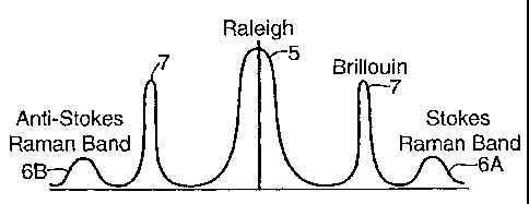
Figure 2 illustrates that the backscattered light
includes different spectral components which contain
peaks that are known as Rayleigh and Brillouin peaks and
Raman bands. The Rayleigh peak 5 is independent of
temperature but is useful in identifying breaks and
inhomogeneities along the fiber. The Raman spectral
bands 6 are caused by thermally influenced molecular
vibrations. These are naturally occurring phenomena in
glass as well as in fluids, gases and solids. The Raman
spectral bands 6 can be used to obtain information about
distribution of temperature along the well.
The Raman backscattered light has two components,
Stokes 6A and Anti-Stokes 66, one being only weakly
dependent on temperature and the other being greatly
influenced by temperature. The relative intensities
between the Stokes and Anti-Stokes components 6A and 66
are a function of temperature at which the backscattering
CA 02551283 2006-06-22
WO 2005/064117
PCT/EP2004/053675
- 9 -
occurred. Therefore, temperature can be determined at any
point along the length of the optical fiber 1 by
comparing at each point the Stokes and Anti-stokes
components 6A and 63 of the light backscattered from the
particular point. The Brillouin peaks 7 may be used to
monitor strain along the length of the optical fiber 1.
Figure 3 shows how an optical DTS fiber 1 is arranged
in the horizontal inflow region 10 and the vertical riser
section of a well 11. The well 11 is equipped with a
0.6 cm (;.1 inch) OD control line 12 through which a
Mineral Insulated (MI) heater cable 13 and lead in
cable 19 extend. This control line 12 may be installed
either outside or inside the well casing 20, liners
and/or perforated sandscreen 22 in the horizontal inflow
region 10 of the well 11. Electrical power is supplied to
the lead in cable 19 by an electrical power supply
source 21. Pulsed laser light signals are supplied to the
optical fiber 1 by the laser light source 2 and the light
spectrum backscattered from different points along the
length of the optical fiber 1 is reflected by a
directional coupler 3 to a receiver 4. The receiver 4 is
equipped with a light processing unit in which in
particular the Stokes and anti-Stokes Raman bands 6A and
6B of the backscattered light are converted into a signal
which is related to the temperature of the optical
fiber 1 at the point where the light pulse has been
reflected in accordance with the description provided
with reference to Figures 1 and 2.
The mineral insulated (MI) heater cable 13 is made up
of an outer metal sheath 14, usually cylindrical, that
contains a concentric solid metal rod 15. The annular
space between the sheath 14 and the metal rod 15 is
filled with an insulant 16, usually in powder form, that
CA 02551283 2006-06-22
WO 2005/064117
PCT/EP2004/053675
- 10 -
is a good electrical insulator and a reasonable thermal
conductor. The metal rod 15 or core is used to conduct a
current, usually AC, which generates heat by ohmic
dissipation. The MI heater cables 13 may be operated
under DC conditions or under AC single-phase or AC three-
phase conditions. The length of the MI heater cables 13
can vary from 15 to 1000 m. For monitoring influx into an
oil production well a suitable length along with the well
inflow region is heated may be about 250 in.
The MI heater cable 13 may be configured to deliver
between 0 and 1 KW/m with larger powers easily achieved
for shorter heater cables. The power level is such that
the core temperature must not exceed a maximum value
related to the breakdown strength of the insulant 16 and
the sheath temperature must not exceed a maximum
temperature related to the corrosion resistance of the
sheath alloy. This means that the core temperature is in
the 650 to 870 Degrees Celsius (1200 F to 1600 F) range
and the sheath temperature in the 540 to 760 Degrees
Celsius (1000 F to 1400 F) range.
The heater assembly may consist of one or multiple MI
heater cables 13 placed in the well. The heater(s) can
support its (or their) own weight if the sheath
temperature is less than 540 Degrees Celsius (1000 F).
This temperature could be higher with more creep
resistant alloys. The MI heater cables 13 can also be
strapped to a support tube or support cable. A suitable
mode is to have three heater cables strapped to a support
and operated with 60-cycle AC voltage in a three-phase Y
configuration.
The DTS optical fiber 1 may extend through a
channel 18 in the insulant 16 of a MI heater cable 13 as
illustrated in Fig. 3 and 4 or may be installed
CA 02551283 2006-06-22
WO 2005/064117
PCT/EP2004/053675
- 11 -
separately from the MI heater cable or cables 13, such as
by strapping a guide tube containing the fiber 1 to the
outer surface of MI heater cable 13 or to the support
tube or support cable. The guide tube may be U-shaped
such that a double-ended optical fiber can be injected
into the guide tube after installation of the guide tube
in the well 11 and/or to replace a damaged optical
fiber 1.
The heater assembly is configured such that the
voltage between the central metal rod 15 and sheath 14 is
substantially below the breakdown voltage of the
insulant 16 at the expected operating temperature of the
heater. The sheath alloy has to have a low enough
corrosion rate such that a substantially low fraction of
its thickness is negatively affected by corrosion over
the lifetime required of the heater. The mechanical
strength of the heater assembly has to be sufficient to
avoid elongation damage to the MI heater cables 13 when
suspended vertically in the well. For most of the
applications in DTS measurements these conditions should
be satisfied.
Suitable embodiments for the various components of
the MI heater cable 13 are described in more detail
below.
The sheath 14 is a metallic tubular that forms the
outer part of the MI heater cable 13. The sheath 14
material will be in contact with formation fluids. Its
metallurgy has to be good enough to resist corrosion in
the heated formation environment. Alloys that can be used
in the temperature range indicated include SS 304,
SS 310, Incoloy 800 and Inconel 600.
The sheath 14 as well as the cold pins and the
splices described below have to devoid of holes that
CA 02551283 2006-06-22
WO 2005/064117
PCT/EP2004/053675
- 12 -
might allow moisture into the insulant 16. Excessive
moisture in the insulant 16 can lead to a drop in
insulant resistivity and/or a chemical change leading
again to a drop in resistivity.
The metal rod 15 is configured to deliver the
appropriate power. A given heater can have one or more
metal rods 15 within a single sheath 14 and one or more
than one heater can be strapped together in a bundle
within a well. The power dissipation required per
conductor is equal to the total power dissipation per
well divided by the total number of conductors. In a
suitable configuration three single conductor MI heater
cables 13 are strapped to a support member (not shown).
The metal rods 15 of the MI heater cables 13 have a
diameter and a resistivity at operating temperature that
satisfies Ohm's law for the chosen power dissipation per
foot, the length of the heater and the maximum voltage
allowed. Materials that can be used for the metal rods 15
include nichrome, nickel, and a number of alloys made
from copper and nickel in increasing nickel
concentrations from pure copper to Alloy 30, Alloy 60,
Alloy 180 and Monel. Nickel-copper alloys are preferred
because they have a lower temperature resistivity
coefficient than the pure metals. A preferred material is
Alloy 60. If high power dissipation is required for
shorter length heaters a Nichrome core can be used.
The insulant 16 may comprise a variety of materials
such as powdered oxides that offer high breakdown
strength and high resistivity at the target temperature.
The commonly used powders include MgO, AL203, Zirconia,
Be0 and different chemical variations of Spinels. A
preferred material is MgO. Breakdown voltage and
resistivity are affected by the type and quantity of
CA 02551283 2006-06-22
WO 2005/064117
PCT/EP2004/053675
- 13 -
impurities in the powders and by the porosity of the
powder in the finished heater product. These
characteristics also depend on the method used to
fabricate the heater. Different methods and different
insulants16 may be selected depending on the required
temperature and electrical operating characteristics of
the MI heater cable 13. To avoid damage to the MI heater
cable 13 at any hot spots it is preferred that the
finished MI heater cable 13 is configured to withstand at
least 2-3 times the operating voltage at the operating
temperature. Preferably, the MI heater cable 13 is
configured withstand 1000 VAC at the maximum temperature
expected in the well.
Preferred mineral powders for use in the insulant 16
are the "H" mix powder manufactured by Idaho Laboratories
Corporation and the Standard Mg() powder used by Pyrotenax
Cable Company for high temperature applications.
The heated section of the heater is normally
connected to a lead-in cable 19 that penetrates the
overburden. The MI heater cable 13 operates at the
maximum temperature required for the DTS measurements
while the lead-in cable 19 is normally rubber insulated
and cannot exceed 65 Degrees Celsius (150 F) (although
more expensive lead-in options can be used either rubber
insulated or made from MI cable also). An economic
solution is to place a short transition section 13A of MI
cable 13 between the heated section and the lead-in
cable. This transition section 13A of MI cable 13 is made
from a less resistive core than the heated section in
order to decrease the power dissipation along its length
and therefore lower its temperature. Alloys of the type
listed above can be used with varying diameters and the
cold pin lengths can vary from 1.5 to 15 m. A preferred
CA 02551283 2006-06-22
WO 2005/064117
PCT/EP2004/053675
- 14 -
mode is a 10 m cold pin filled with the same insulant 16
as the heated section. A suitable sheath for the cold pin
is Inconel 600. To inhibit chloride corrosion cracking in
the cold-pin region the sheath 16 of the transition
section may comprise Inconel 600 for corrosion protection
of this type. In addition to cold-pins at the top one
might elect to also place cold-pins at the end of the
heated section. This can make the bottom termination
easier to manufacture but adds cost.
The transition from the heated section to the cold
pin has to withstand a temperature equal to half of the
target zone operating temperature at the required
operating voltage. The final density of the insulant in
the splice has to be high enough for this purpose.
Preferably the splice is configured to withstand 1000 VAC
at 480 Degrees Celsius (900 F). High temperature splices
are made by different manufacturers, such as Idaho
Laboratories Corporation or Pyrotenax Cable Company.
The end of the cold-pin may be connected to a long
length of flexible rubber insulated copper conductor. The
connection may be a standard epoxy filled small canister
made by the major heater suppliers. This cable is very
similar to typical downhole electrical submersible pump
(ESP) cable. Its main characteristic has to be the
ability to withstand maximum overburden temperatures and
be impermeable to the fluid environment in the well.
The heater assembly can be made such that one has one
or several cables powered in parallel with the ends of
the cables all at the top. This option called the "hair-
pin" option does not require a bottom termination.
If the heater assembly consists of one or more MI
heater cables 13 in the 3-phase Y configuration they can
be used with no connection at the bottom or with all
CA 02551283 2006-06-22
WO 2005/064117
PCT/EP2004/053675
- 15 -
three-phase cores connected at the bottom. This last
option is preferred. This connection can be made directly
at the end of the heated section or at the end of cold-
pins attached to the end of the heated section, similarly
to the top cold-pins. A preferred mode is to use bottom
cold-pins with the three-phase conductors electrically
connected at the end of the bottom cold-pins. This
connection is made within an MgO filled and sealed can or
with an epoxy filled can. A preferred mode is an MgO
filled can using the same MgO as the one used in the
heated section. The final choice of termination will
depend on the space available within the well 11 in
addition to the DTS fiber 1 installed. A suitable
MI heater cable configuration is disclosed in
International patent application WO 0183940.
The finished heater assembly needs to be examined for
competent welds, no holes in the sheath anywhere along
the whole heater assembly
A suitable operational procedure to obtain a
quantitative multi-phase inflow distribution with a
Distributed Temperature System(DTS) optical fiber 1 in
combination with a heater assembly comprising one or more
MI heater cables 13 comprises the following five steps:
1. Obtain a steady-state temperature profile under
producing conditions.
2. Shut the well and again obtain a steady-state
temperature profile. This profile is representative for
the geothermal gradient and is referred to as a base line
temperature profile.
3. Heat the well at a specified power input and obtain a
steady-state temperature profile. The transient behaviour
and the time it takes to get from step 2 to 3 allows the
heat properties in the system to be determined.
CA 02551283 2006-06-22
WO 2005/064117
PCT/EP2004/053675
- 16 -
4. Put the well back under producing condition with the
heater still on. Obtain a steady-state temperature
profile.
5. Turn off the heater and obtain a steady state
temperature profile (the same as the temperature profile
in step 1. The transient behaviour and the time it takes
to get from step 4 to 5 can be used to determine an
inflow distribution for the different phases.
Steps 1 and 2 form part of the known procedure for
obtaining temperature data with DTS in order to obtain a
qualitative "single-phase" (total liquid) inflow
distribution.
Steps 3 to 5 are the additional steps required to go
from a qualitative to a quantitative multi-phase
measurement with the use of a heater.
Simulations of the method according to the invention
have been carried out with a thermal reservoir model. In
figure 5, simulated results are shown for a well with a
horizontal section of 600 meters. The horizontal section
has been subdivided into three areas with different
reservoir characteristics, i.e. different permeabilities
of 10, 250 and 100 mD, respectively. Thus, the reservoir
has a decreasing permeability along the well.
The lower horizontal line 30 shows the temperature
profile of a well that is shut-in just before the heater
is activated. The upper horizontal line 31 shows the
temperature profile after 48 hour of heating up the well
with 90 W/m (So about 60 kW for the whole horizontal
sections). After 48 hours the heater is turned off and
the well is put on production. The rest of the
temperature profiles 32-37 show the temperature response
over time. The time it takes for the well to cool down to
CA 02551283 2006-06-22
WO 2005/064117
PCT/EP2004/053675
- 17 -
the temperature profile 37 prior to shut-in can be
correlated to the inflow from the reservoir.
A physical model that demonstrates that the method
according to the invention can be used to estimate the
velocities and/or composition, such as the watercut, of
the fluids flowing into the well is as follows.
If a fluid is not in thermal equilibrium with the
porous medium it is flowing through, heat will either be
extracted or provided to the medium. The temperature of
the moving fluid changes corresponding to the temperature
of the porous medium and depending on its heat capacity.
The basic equation is
(P* f
WVT) .Wv.T)=0
X (1)
whereVis the spatial derivative, T is temperature, p is
density and c is heat capacity of the fluid, X is thermal
conductivity of the saturated medium, and V is the Darcy
velocity of the fluid, which can be translated into the
actual flow velocity V by
v
V= -
(2)
where 4 is the porosity.
For one spatial component, e.g. the vertical
direction z, the analytic solution to equation (1) is
exp{z.Pel
T=To+(TL-To)-
explz=Pe}-1 (3)
where To is the temperature at z = 0, TL is the
temperature at z = L, L is the section of interest, and
Pe is the Peclet number, defined as the ratio of
convective to conductive heat flow
CA 02551283 2006-06-22
WO 2005/064117
PCT/EP2004/053675
- 18 -
=Pe = (p = c)
L vz
(4)
where vz is the vertical component of v.
Integration of equation (1) with respect to z and
evaluating the undetermined constant at z = 0 (where
T = To) yields
am Pe m.0 a
¨ + m
az az õ, ( 5 )
For the other spatial components, x and y, the
calculations are accordingly.
Therefore, determining Pe from the slope of a
temperature gradient versus temperature plot (and
assuming a value for L) allows to relate thermal
measurements directly to fluid velocities with
equation (4).
The derived Darcy velocity is directly dependent on
the heat capacity of the fluid. The values for water and
oil are 4.0 kJ kg-1 K-1 and 1.8 kJ kg-1 K-1,
respectively. This means that for a certain Peclet number
the uncertainty for the derived Darcy velocity is 26%
if the water cut is not known. On the other hand, if the
flow rate is known the Peclet number can be used to
estimate the water cut.
The Peclet number analysis is only capable to provide
an estimate (limited to one-dimensional flow) of the flow
rate. Numerical modelling of coupled heat- and fluid-flow
and fitting the accuired data is a more appropriate
evaluation approach.
High-resolution temperature measurements over time
have been used in geothermal studies to quantify water
flow in the formation (assuming there is no flow in the
well during the measurement). Thermal recovery of a well
CA 02551283 2006-06-22
WO 2005/064117
PCT/EP2004/053675
- 19 -
after drilling operations, which is equivalent to
monitoring the well temperature during shut-in after
production or heating, allowed to identify fractured
zones and characterize formation layers with different
permeability. The Peclet number analysis may be used to
derive natural flow velocities in the formation. Again,
temperatures may be measured after thermal equilibrium of
the well and in the absence of flow in the well. Any flow
in the well will dominate over the thermal signal from
the formation.