Note: Descriptions are shown in the official language in which they were submitted.
CA 02551947 2006-07-13
DCO-P0002 -I- Express Mail No. EV 736438248 US
LOAD SENSE BOOST DEVICE
Background of the Invention
[ 1] The present invention relates generally to hydraulic control systems.
More particularly, the present invention relates to a hydraulic control system
that
maintains a reserve capacity for use by a hydraulic device.
Background and Summary
[2] Many pieces of construction equipment use hydraulics to control the
functions performed by the equipment. For example, many pieces of construction
equipment use hydraulics to control the brakes. If pressure is lost in the
hydraulic
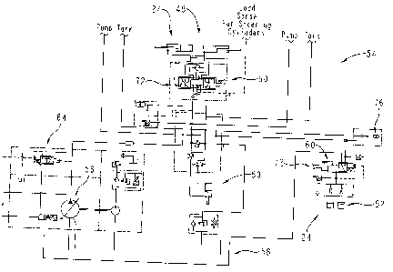
system, it is important that the brakes continue to operate so that the
operator can stop
the piece of equipment.
[3] According to one aspect of the present invention, a vehicle is provided
including a frame, a plurality of traction devices configured to propel the
frame on the
ground, a plurality of hydraulic actuators, brakes configured to control the
speed of
the vehicle, and a hydraulic control system. The hydraulic control system
includes a
pressure source providing pressurized hydraulic fluid, a load sense system
detecting
the maximum pressure needed by the plurality of hydraulic actuators during
operation
of the vehicle, and a plurality of hydraulic controls controlling the supply
of
pressurized fluid to the plurality of hydraulic actuators. The plurality of
hydraulic
controls uses the maximum pressure detected by the load sense system to
regulate the
pressure of the hydraulic fluid provided to the plurality of hydraulic
actuators. The
hydraulic control system further includes a pressure source control coupled to
the load
sense system and pressure source to control the pressure output from the
pressure
source based on the maximum pressure detected by the load sense system, a load
sense input to the load sense system that maintains the maximum pressure
detected by
the load sense system at least at a predetermined pressure, and a hydraulic
fluid
accumulator supplying pressurized fluid to the brakes.
[4] According to another aspect of the present invention, a vehicle is
provided including a frame, a plurality of traction devices configured to
propel the
frame on the ground, a plurality of hydraulic actuators, and a hydraulic
control
system. The hydraulic control system includes a hydraulic pump providing
pressurized hydraulic fluid and a load sensor configured to detect the maximum
CA 02551947 2009-06-18
77580-36
-2-
pressure needed by the plurality of hydraulic actuators. The load sensor
provides a
signal indicative of the maximum pressure. The signal controls the pressure of
the
hydraulic fluid output from the hydraulic pump. The hydraulic control system
further
includes a plurality of pressure compensators provided for the plurality of
hydraulic
actuators. Each of the pressure compensators provides pressurized fluid to at
least
one corresponding hydraulic actuators based on the signal from the load sensor
and
the necessary load pressure from the corresponding hydraulic actuator. The
hydraulic
control system further includes a signal regulator maintaining the signal
above a
predetermined level.
[5] According to another aspect of the present invention, a vehicle is
provided including a frame, a plurality of traction devices configured to
propel the
frame on the ground, a plurality of hydraulic actuators, and a hydraulic
control
system. The hydraulic control system includes a pressure source providing
pressurized hydraulic fluid, a plurality of hydraulic controls regulating the
supply of
pressurized fluid to the plurality of hydraulic actuators, a load sensor
detecting the
maximum pressure needed by the plurality of hydraulic actuators and providing
a
hydraulic signal indicative of the maximum pressure, a pump control receiving
the
hydraulic signal from the load sensor and controlling the output pressure from
the
source of pressurized fluid, and a load signal regulator maintaining the
hydraulic
signal above a predetermined level that is less than the output pressure of
the source
of pressurized fluid.
CA 02551947 2009-06-18
77580-36
2a
According to another aspect of the invention, there is provided a
vehicle including a frame, a plurality of traction devices configured to
propel the
frame on the ground, a plurality of hydraulic actuators, brakes configured to
control the speed of the vehicle, and a hydraulic control system including a
pressure source providing pressurized hydraulic fluid, a load sense system
detecting the maximum pressure needed by the plurality of hydraulic actuators
during operation of the vehicle, a plurality of hydraulic controls controlling
the
supply of pressurized fluid to the plurality of hydraulic actuators, the
plurality of
hydraulic controls using the maximum pressure detected by the load sense
system to regulate the pressure of the hydraulic fluid provided to the
plurality of
hydraulic actuators, a pressure source control coupled to the load sense
system
and pressure source to control the pressure output from the pressure source
based on the maximum pressure detected by the load sense system, a load sense
input to the load sense system that maintains the maximum pressure detected by
the load sense system at least at a predetermined pressure, and a hydraulic
fluid
accumulator supplying pressurized fluid to the brakes.
According to another aspect of the invention, there is provided a
vehicle including a frame, a plurality of traction devices configured to
propel the
frame on the ground, a plurality of hydraulic actuators, and a hydraulic
control
system including a hydraulic pump providing pressurized hydraulic fluid, a
load
sensor configured to detect the maximum pressure needed by the plurality of
hydraulic actuators, the load sensor providing a signal indicative of the
maximum
pressure, the signal controlling the pressure of the hydraulic fluid output
from the
hydraulic pump, a plurality of pressure compensators provided for the
plurality of
hydraulic actuators, each of the pressure compensators providing pressurized
fluid to at least one corresponding hydraulic actuators based on the signal
from
the load sensor and the necessary load pressure from the corresponding
hydraulic
actuator, and a signal regulator maintaining the signal above a predetermined
level.
According to another aspect of the invention, there is provided a
vehicle including a frame, a plurality of traction devices configured to
propel the
frame on the ground, a plurality of hydraulic actuators, and a hydraulic
control
CA 02551947 2009-06-18
77580-36
2b
system including a pressure source providing pressurized hydraulic fluid, a
plurality of hydraulic controls regulating the supply of pressurized fluid to
the
plurality of hydraulic actuators, a load sensor detecting the maximum pressure
needed by the plurality of hydraulic actuators and providing a hydraulic
signal
indicative of the maximum pressure, a pump control receiving the hydraulic
signal
from the load sensor and controlling the output pressure from the source of
pressurized fluid, and a load signal regulator maintaining the hydraulic
signal
above a predetermined level that is less than the output pressure of the
source of
pressurized fluid.
[6] Additional features of the present invention will become apparent to
those skilled in the art upon consideration of the following detailed
description of
the presently perceived best mode of carrying out the invention.
Brief Description of the Drawings
[7] The detailed description of the drawings particularly refers to the
accompanying figures in which:
[8] Fig. 1 is a side elevation view of a grader showing the grader
including a frame, a cab supported by the frame, a blade extending below the
frame, and a plurality of wheels supporting the frame on the ground;
[9] Fig. 2 is a schematic view of a portion of a hydraulic control system
of the grader of Fig. 1 showing a pump drawing hydraulic fluid from a tank, a
pair
of steering cylinders, and a hydraulic brake system;
CA 02551947 2009-06-18
77580-36
-3-
[10] Fig_ 3 is a schematic view of another portion of the hydraulic control
system showing a left bank of hydraulic control valves and the hydraulic
devices
controlled by the control valves; and
[ 11) Fig. 4 is a schematic view of another portion of the hydraulic control
system showing a right bank of hydraulic control valves and the hydraulic
devices
controlled by the control valves.
Detailed Description of the DrawinQs
[12) A motor grader 10 is shown in Fig. 1 for spreading and leveling dirt,
gravel, or other materials. Grader 10 includes an articulated frarne 12, a
passenger
cab 13, an plurality of wheels 14 to propel frame 12 the remainder of grader
10 along
the ground, an engine 16 to power operation of grader 10, and a blade 18 for
spreading and leveling. In addition to blade 18, grader 10 is provided with a
scarifier
20 and a ripper 22 for working the soil. Additional details of a suitable
grader are
provided in U.S. Patent No. 6,644,429, titled Hydrostatic Auxiliary Drive
Svstem. to
Evans et a].
[13] To move and power the various components of grader 10, it includes a
plurality of hydraulic actuators 24. As shown in Figs. 2-4, such actuators 24
include
blade-lift cylinders 28 to raise and lower blade 18, scarifier cylinder 30 to
raise and
lower scarifier 20, ripper cylinders 32 to raise, lower, and operate ripper
22, a blade
side shift cylinder 34 to shift blade 18 laterally, a blade tilt cylinder 36
to adjust the
tilt of blade 18, articulation cylinders 38 to power articulation of frame 12,
blade
circle rotation motor 40 to permit rotation of blade 18 about a vertical axis,
a circle
side shiffl cylinder 42, a wheel lean cylinder 44 to control the tilt of front
wheels 14
during turning, auxiliary cylinders 46 for optional features, steering
cylinders 48 to
control the direction of front wheels 14, saddle locking pin cylinder 50, and
brake
pistons 52 of the brakes to control the speed of grader 10.
[14] To power and control hydraulic actuators 24, grader 10 includes a
hydraulic control system 54 as shown in Figs. 2-4. Hydraulic control system 54
includes a pressure source or hydraulic pump 56 that pressurizes the hydraulic
fluid
and a hydraulic fluid tank 58 that receives hydraulic fluid back from
actuators 24.
Hydraulic control system 54 also includes a plurality of hydraulic controls 60
that
control the flow and pressure of hydraulic fluid provided to actuators 24.
CA 02551947 2006-07-13
DCO-P0002 -4- Express Mail No. EV 736438248 US
[15] Hydraulic control system 54 operates at a range of pressures depending
on the needs of actuators 24. System 54 includes a load sensor or load sense
system
62 that detects the maximum pressure required by actuators 24 and a pressure
source
control or pump control 64 that controls the output pressure from pump 56.
Load
sense system 62 sends a hydraulic signal to pump control 64 so that pump 56
provides
enough pressure at any given time to operate the actuator 24 that needs the
maximum
pressure.
[16] As shown in Figs. 3 and 4, load sense system 62 includes a plurality of
shuttle disks or comparators 66 that communicate with actuators 24 to
determine their
current pressure load or pressure need. Each comparator 66 includes a pair of
inputs
and an output. Typically, each comparator 66 receives a pressure signal from
another
comparator 66 and an actuator 24 through one of the plurality of controls 60.
Each
comparator 66 provides an output equal to the higher signal. As shown in Fig.
4, for
example, comparator 66a receives a signal from circle side shift cylinder 42
and a
signal from comparator 66b associated with wheel lean cylinder 44. If it is
assumed
that the pressure load need from circle side shift cylinder 42 is 1500 psi and
the output
signal pressure from wheel lean cylinder 44 is 1350 psi, comparator 66b will
output a
hydraulic signal of 1500 psi, the higher of the two signals, to comparator 66c
associated with articulation cylinders 38.
[17] Each actuator 24 has an associated comparator 66 and all comparators
66 are coupled together in series so that maximum pressure needed by the
comparators 66 is determined. As shown in Fig. 3, comparator 66d is the last
comparator 66 in the series of comparators 66. Comparator 66d provides a
hydraulic
signal to pump control 64 equal to the maximum pressure input to system 64.
Based
on the signal, pump control 64 adjusts the output pressure of pump 56 to
provide
sufficient pressure to operate the actuator 24 requiring the most pressure
(circle side
shift cylinder 42 in the example). Pump control 64 regulates pump 56 to
provide an
output pressure that is 400 psi greater than the hydraulic signal provided by
comparator 66d. The 400 psi difference compensates for pressure losses between
the
output of pump 56 and the actuator requiring the most pressure.
[18] Pump 56 provides hydraulic fluid at the maximum needed pressure to
each of the hydraulic controls 60. Each hydraulic control 60 includes a spool
valve 72
that regulates the flow rate and direction of flow of hydraulic fluid to each
actuator 24
and a pressure compensator 74 that regulates the pressure of the hydraulic
fluid
CA 02551947 2006-07-13
DCO-P0002 -5- Express Mail No. EV 736438248 US
supplied to each actuator 24. An operator controls the position of spool
valves 72
using levers to control the flow rate and direction of flow of fluid to
actuators 24.
Pressure compensators 74 receive the hydraulic signal from comparator 66d that
indicates the maximum pressure needed by actuators 24. Using this signal as a
pilot
signal and another pilot signal sent from the respective actuator 24 through
spool
valve 72, pressure compensators 74 provide hydraulic fluid back to spool valve
72
and the respective actuators 24 at the required pressure for each respective
actuator
24. If an actuator 24 requires the maximum pressure indicated by the signal
from
comparator 66d, the respective compensator 74 provides that pressure. If an
actuator
24 requires less than the maximum pressure, the respective compensator 74
provides a
pressure drop that lowers the fluid pressure to the pressure required for the
respective
actuator 24.
[19] For example, as described above, it was assumed that side shift
cylinder 42 needed 1500 psi of pressure and wheel lean cylinder 44 needed 1350
psi
of pressure. Assuming 1500 psi was the maximum pressure required for all
actuators
24, hydraulic pump 56 would output 1900 psi (1500 psi + 400 psi), compensator
74a
associated with side shift cylinder 42 would provide no pressure drop (other
than
some inherent pressure drop), and compensator 74b associated with wheel lean
cylinder 44 would provide 150 psi pressure drop. Because of the inherent
pressure
drops between pump 56 and side shifl cylinder 42 (approximately 400 psi), 1500
psi
of pressure is supplied to side shift cylinder 42 and 1350 psi of pressure is
supplied to
wheel lean cylinder 44. Thus, although one or more of actuators 24 is
operating at the
maximum needed pressure, other actuators 24 are operating at lower pressures
because they do not require the higher maximum pressure.
[20] As shown in Fig. 2, hydraulic system 54 also includes an accumulator
76 that supplies hydraulic fluid to brake pistons 52. Accumulator 76 receives
pressurized fluid from pump 56 with little pressure loss. To actuate the
brakes six
times, accumulator 76 needs approximately 1300 psi of pressure. Thus, if
sufficient
pressure is unavailable from pump 56, brakes can be operated at least six
times to
bring grader 10 to a stop.
[21] To maintain 1300 psi of pressure in accumulator 76, the outlet pressure
of pump 56 is also normally maintained at 1300 psi. Because the necessary
pressure
required by actuators 24 may not always provide for 1300 psi of pressure,
hydraulic
control system 54 includes a load boost input or signal regulator 78, shown in
Fig. 4,
CA 02551947 2006-07-13
DCO-P0002 -6- Express Mail No. EV 736438248 US
that maintains the minimum hydraulic signal from comparator 66d at 900 psi. As
a
result, pump control 64 maintains the normal output pressure from pump 56 at a
minimum of 1300 psi.
[22] As shown in Fig. 4, signal regulator 78 is preferably a pressure
reducing valve having an output pressure of 900 psi. Under normal operating
conditions, signal regulator 78 receives hydraulic fluid from pump 56 at a
minimum
of approximately 1300 psi. During operation of actuators 24, signal regulator
78 may
receive hydraulic fluid from pump 56 up to 2,750 psi. Regardless of what
pressure
regulator 78 receives from pump 56 during normal operation, the pressure
signal from
regulator 78 is about 900 psi.
[23] As shown in Fig. 4, this 900 psi pressure signal is feed into load sense
system 62. Thus, load sense system 62 will always have at least one input
providing a
hydraulic pressure signal of at least 900 psi. Even if all actuators 24
require less than
900 psi, the output from comparator 66d to pump control 64 will be 900 psi and
the
output from pump 56 will be 1300 psi.
[24] At startup and other times, it is possible that the pressure provided to
signal regulator 78 will be below 900 psi. Assuming the pressure output from
pump
56 is initially 0 psi, comparator 66d will also provide a signal to pump
control 64 of 0
psi and pump control 64 will instruct pump 56 to have an output of 400 psi
which is
then provided to signal regulator 78. Signal regulator 78 will then provide a
400 psi
signal to comparator 66d which is transmitted to pump control 64 to boost the
output
pressure of pump 56 to 800 psi. This feedback continues until the output
pressure of
pump 56 reaches 1300 psi to keep accumulator 76 or any other hydraulic device
at the
necessary pressure.
[25] The control system above has been described in reference to a grader.
According to other embodiments of the present disclosure, the control system
may be
provided on other vehicles such as articulated dump trucks, backhoe loaders,
dozers,
crawler loaders, excavators, skid steers, scrapers, trucks, cranes, or any
other type of
vehicles known to those of ordinary skill in the art. In addition to wheels,
other types
of traction devices may be provided on such vehicles such as tracks or other
traction
devices known to those of ordinary skill in the art.
[26] Although the invention has been described in detail with reference to
certain preferred embodiments, variations and modifications exist within the
spirit and
scope of the invention as described and defined in the following claims.