Note: Descriptions are shown in the official language in which they were submitted.
CA 02552339 2011-07-07
-2-
SELF TESTING DIGITAL FAULT INTERRUPTER
Field of the Invention
[0002] The present invention relates generally to a self testing fault
interrupting
device, such as a ground fault circuit interrupter or an arc fault circuit
interrupter. More
particularly, the present invention relates to a self testing fault
interrupting device where
at least one of a daily or a once a minute self test is performed
automatically and
independently of a manual test.
Background of the Invention
[0003] Fault interrupting devices are designed to trip in response to the
detection of
a fault condition at an AC load. The fault condition can result when a person
comes into
contact with the hot side of the AC load and an earth ground, a situation
which can
result in serious injury. A ground fault circuit interrupter (GFCI) detects
this condition
by using a sense transformer to detect an imbalance between the currents
flowing in the
line and neutral conductors of the AC supply, as will occur when some of the
current on
the load hot side is being diverted to ground. When such an imbalance is
detected, a
relay or circuit breaker within the GFCI device is immediately tripped to an
open
condition, thereby removing all power from the load.
[0004] Many types of GFCI devices are capable of being tripped not only by
contact
between the line side of the AC load and ground, but also by a connection
between the
neutral side of the AC load and ground. The latter type of connection, which
may result
from a defective load or from improper wiring, is potentially dangerous
because it can
prevent a conventional GFCI device from tripping at the required threshold
level of
differential current when a line-to-ground fault occurs.
[0005] A ground fault is not the only class of potentially dangerous abnormal
operating conditions. Another type of undesirable operating condition occurs
when an
electrical arc jumps between two conductors or from one conductor to ground
also
known as an arcing path. This spark represents an electrical discharge through
the air
CA 02552339 2006-07-14
-3-
and is objectionable because heat is produced as an unintentional by-product
of the
arcing. Such arcing faults are a leading cause of electrical fires.
[0006] Arcing faults can occur in the same places that ground faults occur; in
fact, a
ground fault would be called an arcing fault if it resulted in an electrical
discharge, or arc,
across an air gap. A device known as an arc fault circuit interrupter (AFCI)
can prevent
many classes of arcing faults. Both GFCIs and AFCIs are referred to as fault
protection
devices.
[0007] Prior art self testing fault protection devices typically provide a
self test which
replaces a user having to perform manual tests at fixed periods of time, for
example,
weekly, monthly, and so on. Because the user relies on the self testing fault
protection
device to perform self-tests, the user may have a false sense of security. For
example,
many self testing fault protection devices only test for electronic operation
and do not
test for the opening and closing of contacts of the self testing fault
protection device. If
there is a defect with a component other than the electronics, a user can
believe that the
device is providing fault protection and can inadvertently be injured.
[0008] Also, as a solenoid of a fault protection device is operated over time,
the
semiconductor that is used to operate the solenoid can become degraded to a
point
where it approaches failure. This occurs because a 500 volt transient is
placed across the
transistor every time the solenoid is deenergized. Many manufacturers of fault
protection
devices place a diode between the solenoid and transistor. The diode is
referred to as a
suppressor diode. However, placing a suppressor diode across the solenoid or
from the
transistor collector to ground significantly lengthens the time to open
contacts to break a
conductive path. Since a life may be involved, time is of the essence
regarding quickly
opening the contacts of the fault protection device.
[0009] Another problem with conventional fault protection devices is that
their load
or feed-through terminals are hard wired to the face receptacles of the GFCI
or AFCI.
Therefore, if a user miswires the GFCI or AFCI by connecting the hot and
neutral lines
to the load terminals and equipment is plugged into the GFCI or AFCI via the
face
receptacles, the face receptacles can still be powered even if the GFCI or
AFCI is in a
tripped or off state. This can lead to potential injury to the user because
the user would
CA 02552339 2006-07-14
-4-
be under the impression that the GFCI or AFCI is in a tripped condition that
always
provides protection.
[0010] Still another problem with conventional fault protection devices is
that
electrical sparks associated with the input power line sometimes occur when
the contacts
of the protection device close. The high temperatures associated with the
electrical sparks
sometimes deteriorate the non-metallic housing of the protection device.
Current
solutions such as making the walls of the protection device thicker are not
cost effective.
[0011] Thus, there is a need for a fault protection device which allows for a
quick
response in opening the contacts of the fault protection device without
damaging the
transistor or adding a delay in responding to a fault condition.
[0012] Still yet another need exists for a fault protection device that has
face
receptacles that are isolated from the load terminals.
[0013] Still another need exists for a fault protection device that allows the
fault
protection device to self-test without providing a momentary interruption in
power to
current sensitive equipment.
[0014] A further need exists for a structural housing that is resistant to
burning or
melting from the high temperatures related to electrical arcs. The structure
should also
provide an arrangement that maximizes space on a printed circuit board.
Summary of the Invention
[0015] An embodiment of the present invention provides a self testing fault
detector
having a line side and a load side and a conductive path therebetween. The
apparatus
includes a solenoid which is adapted to move a plurality of contacts disposed
in the
conductive path from a first position to a second position when the self
testing device is
powered from the line side, and a processor which is adapted to energize the
solenoid
using a first switch and maintain said solenoid in the energized state using a
second
switch.
CA 02552339 2011-07-07
-4A-
[0015A] A further embodiment of the present invention provides a self testing
fault
detector and interrupter having a line side and a load side and a conductive
path
therebetween. The apparatus comprises a solenoid adapted to move a plurality
of contacts
disposed in the conductive path from a first position to a second position
when the self
testing fault detector is powered from the line side, a programmable processor
programmed to energize the solenoid by activating a first switch using a first
output thereof
for a selected period of time determined by the processor and to maintain the
solenoid in
the energized state by activating a second switch using a second output
thereof after the
selected period of time has elapsed and deactivating the first switch. A
Ground Fault Circuit
Interrupter (GFCI) chip is configured to detect an occurrence of a ground
fault, and has an
output to the second switch to control deenergization of the solenoid
independently of the
processor when a fault condition is detected.
[0015B] A further embodiment of the present invention provides a self testing
fault
interrupter apparatus having line terminals and load terminals and a
conductive path
therebetween. The apparatus comprises a fault sensing transformer adapted to
detect a
fault condition in the conductive path, a solenoid adapted to move a plurality
of contacts
disposed in the conductive path from a first position when the solenoid is
deenergized or to
a second position when the solenoid is energized, a microprocessor, and a
fault detection
chip comprising a first output connected to a switch circuit for the solenoid,
and adapted to
place the solenoid in an initial deenergized state and place the contacts in
the first position
independently of the microprocessor when a fault condition is detected by the
fault sensing
transformer. The microprocessor comprises a second output connected to the
switch circuit
for the solenoid, and is adapted to maintain the solenoid in a deenergized
state when the
microprocessor detects that the contacts are in the first position.
[0015C] A further embodiment of the present invention provides a self testing
fault
detector and interrupter having a line side and a load side and a conductive
path
therebetween. the apparatus comprises a solenoid adapted to move a plurality
of contacts
disposed in the conductive path from a first position to a second position
when the self
testing fault detector and interrupter is powered from the line side, and a
processor
CA 02552339 2011-07-07
- 4B -
adapted to energize the solenoid using a first switch and to maintain the
solenoid in the
energized state using a second switch. A processor performs a periodic test
for detecting at
least one of electrical functionality and mechanical functionality of the self
testing fault
detector and interrupter and, if the self testing fault detector and
interrupter is determined
to be inoperable, the self testing fault detector and interrupter is
configured to selectively
operate in a power denial to load state and a receptacle mode of operation
state depending
on which state is selected. The receptacle mode of operation state corresponds
to when
power is provided to a load but the processor does not operate the solenoid to
protect
against a fault.
[0015D] A further embodiment of the present invention provides a self testing
fault
detector and interrupter having a line side and a load side and a conductive
path
therebetween. The apparatus comprises a solenoid adapted to move a plurality
of contacts
disposed in the conductive path from a first position to a second position
when the self
testing fault detector and interrupter is powered from the line side. A
processor is adapted
to energize the solenoid using a first switch and to maintain the solenoid in
an energized
state using a second switch. An alarm indicator is included wherein the alarm
indicator
comprises a red LED that flashes at a first rate when the self testing fault
detector and
interrupter is in a power denial to load state and at a second rate when the
self testing fault
detector is operating in a receptacle mode of operation depending on which
state is
selected. The receptacle mode of operation state corresponds to when power is
provided to
a load but the processor does not operate the solenoid to protect against a
fault.
[0015E] A further embodiment of the present invention provides a self testing
fault
detector and interrupter having a line side and a load side and a conductive
path
therebetween. The apparatus comprises a solenoid adapted to move a plurality
of contacts
disposed in the conductive path from a first position to a second position
when the self
testing fault detector and interrupter is powered from the line side, a
processor adapted to
energize the solenoid using a first switch and to maintain the solenoid in an
energized state
using a second switch, wherein the plurality of contacts comprises a pair of
primary
contacts, a pair of auxiliary contacts and a pair of face contacts and the
primary contacts are
CA 02552339 2011-07-07
-4C-
configured to be open when the auxiliary contacts are closed and to be closed
when the
auxiliary contacts are open. The processor is programmed to perform a self-
test by
controlling the solenoid to deenergize, detecting when the primary contacts
are open via
closure of the auxiliary contacts, and maintaining the primary contacts open
for a selected
period of time to validate a selected signal generated when opening of the
primary contacts
while avoiding disruption operation of a load powered via the self testing
fault detector and
interrupter.
[0015F] A further embodiment of the present invention provides a line powered
self
testing fault protection device having a line side and a load side and a
conductive path
therebetween. The apparatus comprises a solenoid adapted to move a plurality
of contacts
disposed in the conductive path from a first position to a second position, a
fault detector
adapted to energize the solenoid to place the contacts in the first position,
a processor
adapted to energize the solenoid to place the contacts in the second position
via a switch,
and an alarm indicator adapted to indicate at least one of a presence of a
fault, a presence of
electrical power on the line side of said line powered self testing fault
protection device, and
an operational state of the line powered self testing fault protection device.
The operational
state comprises a receptacle mode corresponding to when power is provided to a
load but
the processor does not operate the solenoid to protect against a fault.
CA 02552339 2006-07-14
-5-
Brief Description of the Drawings
[0016] These and other aspects, advantages and novel features of the invention
will
be more readily appreciated from the following detailed description when read
in
conjunction with the accompanying drawings, in which:
[0017] FIG. 1 is a perspective view of an exemplary ground fault circuit
interrupter
(GFCI) device constructed in accordance with an embodiment of the present
invention;
[0018] FIG. 2 is a schematic diagram of a ground fault circuit interrupter in
accordance with an embodiment of the present invention, in which a
conventional GFCI
chip is employed in combination with a microprocessor to operate the GFCI;
[0019] FIG. 3 is a schematic diagram of a ground fault circuit interrupter in
accordance with another embodiment of the present invention, in which a
conventional
GFCI chip is employed in combination with a microprocessor and a bistable
solenoid to
operate the GFCI device;
[0020] FIGS. 4 through 23 are perspective views illustrating components of the
ground fault circuit interrupter disposed on the inner housing of the GFCI in
accordance
with an embodiment of the present invention;
[0021] FIG. 24 is a flow chart of an example of a method for performing a self-
test
in accordance with an embodiment of the present invention;
[0022] FIG. 25 is a flow chart of an example of a method for performing a
ground
fault and manual test in accordance with an embodiment of the present
invention;
[0023] FIG. 26 is a flow chart of an example of a method of a reset button
operation
with the GFCI device in accordance with an embodiment of the present
invention; and
[0024] FIG. 27 is a block diagram of a ground fault circuit interrupter
circuit
configured for responding to an internally generated ground fault and an
externally
generated ground fault in accordance with an embodiment of the present
invention.
Detailed Description Of Exemplary Embodiments
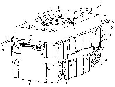
[0025] FIG. 1 is a perspective view of an exemplary fault indication and
protection
circuit 10 in accordance with an embodiment of the present invention. The
fault
CA 02552339 2006-07-14
6-
indication and protection circuit 10 can be a ground fault circuit interrupter
(GFCI), an
arc fault circuit interrupter (AFCI) and/or perform the functions of both an
AFCI and
GFCI. However, for purposes of illustration, the fault indication and
protection circuit
will be described as a GFCI device 10. The GFCI device 10 comprises a housing
12
having a cover portion 14 and a rear portion 16. The GFCI device 10 also
includes a
barrier between the cover portion 14 and the rear portion (e.g., FIGs. 12 and
13) when
the cover portion 14 is removed from the rear portion 16. The cover portion 14
and rear
portion 16 are removably secured to each other via fastening means such as
snaps, barbs,
clips, screws, brackets, tabs and the like. The cover portion includes face
receptacles (also
known as plug/blade slots) 18 and 20 and grounding pin slot 22. It will be
appreciated by
those skilled in the art that face receptacles 18 and 20 and grounding pin
slot 22 can
accommodate polarized, non-polarized, grounded or non-grounded blades of a
male
plug. The male plug can be a two wire or three wire plug without departing
from the
scope of the present invention. The GFCI device 10 further includes mounting
strap 24
having mounting holes 26 for mounting the GFCI receptacle 10 to a junction box
(not
shown). At the rear wall of the housing 12 is a grounding screw 28 for
connecting a
ground conductor (not shown).
[0026] A test button 30 extends through opening 32M' the cover portion 14 of
the
housing 12. The test button 30 is used to activate a test operation that tests
the operation
of the circuit interrupting portion disposed in the GFCI device 10. The
circuit
interrupting portion, to be described in more detail below, is used to break
electrical
continuity between the line and load side of the GFCI device 10. A reset
button 34
extends through opening 36 in the cover portion 14 of the housing 12. The
reset button
34 is used to activate a reset operation, which reestablishes electrical
continuity in the
open conductive paths.
[0027] Rear portion 16 has four screws, only two of which are shown in FIG. 1.
Load terminal screw 38 is connected to a neutral conductor and a load terminal
screw 37
(See FIG. 2) is connected to the hot conductor. Line terminal screw 40 is
connected to
the neutral conductor and a line terminal screw 39 (See FIG. 2) is connected
to the hot
conductor. It will be appreciated by those skilled in the art that the GFCI
receptacle 10
can also include apertures proximate to the line and load terminal screws 37,
38, 39 and
CA 02552339 2006-07-14
-7-
40 to receive the bare end of conductors rather than connecting the bare end
of the wires
to the line and load terminal screws.
[0028] GFCI device 10 also has a power/alarm indicator 42 for providing an
indication to a user that GFCI device 10 is operating normally, the conductive
path
between the line and load terminals is open, or the GFCI device 10 is
operating as a
receptacle without fault protection.
[0029] Power/alarm indicator 42 comprises two separate LEDS a green LED 42A
and a red LED 42B. In an embodiment of the present invention, the green LED
42A is
illuminated when there is power to the GFCI device 10. The red LED 42B is
illuminated
solid if a ground fault is detected via a manual test or an actual ground
fault and the
conductive path between the line and load terminals is open. The red LED 42B
flashes
slow if it is determined during a self-test, a manual test or an actual fault
that the contacts
do not operate properly. Both the green LED 42A and the red LED 42B are off if
the
GFCI device 10 is reverse wired, for example, the input power is connected to
the load
terminals 37 and 38 rather than the line terminals 39 and 40. In another
embodiment of
the present invention, the power/alarm indicator 42 operates in a manner
previously
described except when a determination is made that the GFCI device 10 cannot
provide
ground fault protection, pressing the reset button 34 may allow the contacts
to close and
the red LED 42B flashes fast. The fast flashing indicates to a user that the
GFCI device
is operating as a receptacle that does not provide ground fault protection. It
should be
noted that a flashing red LED 42B indicates that the GFCI device 10 should be
replaced.
It should be appreciated by those skilled in the art that although the
power/alarm
indicator is described as having two separate LEDs, a dual chip LED, separate
colored
lamps, and/or a buzzer can be used among other indicators, to provide an alarm
indication without departing from the scope of the present invention.
[0030] FIG. 2 is a schematic diagram of a ground fault circuit interrupter in
accordance with a first embodiment of the present invention, in which a
conventional
GFCI chip is employed in combination with a microprocessor to operate the
GFCI.
Specifically, the GFCI chip is used to open the contacts while the
microprocessor is used
to maintain the contacts in an open condition. The GFCI device 10 employs a
GFCI
chip 100 with an output 102 connected to a transistor 96, which is in turn
connected to a
CA 02552339 2006-07-14
8-
Darlington transistor 94. A microprocessor 104 is preferably a Type PIC12F629
or
PIG 12F675 microprocessor manufactured by Microchip, located in Chandler,
Arizona.
A transistor 120 is powered, via the microprocessor 104, to energize solenoid
101, thus
closing contacts 62, 66, 68 and 72 to establish a conductive path between line
terminals
39 and 40 and faceplate receptacles 18 and 20 and load or feedthrough
terminals 37 and
38.
[0031] In an embodiment of the present invention, the PIC12F675 microprocessor
104 is used where there is a need for an I/O port to accept more than one
condition. For
example, as an option, the test button 30 and reset button 34 can be voltage
divided to
share an analog I/O port. A voltage divider can be used to distinguish whether
the test
or reset button was pressed. In another embodiment of the present invention,
test button
30 can be eliminated and reset button 34 can be used as a test/reset button.
For example,
microprocessor 104 would distinguish a first press of the button as being a
test and a
second press of the button as being a reset. In another embodiment of the
present
invention, the test button 30 and the reset button 34 can be RC coupled to
produce
signals having different periods of duration which can be detected by the
microprocessor
104.
[0032] The GFCI device 10 employs four sets of contacts, namely contacts 62
and
64, 65 and 66, and 67 and 68, and 70 and 72. Contact 64 establishes electrical
continuity
between line terminal 39 and load terminal 37 via hot conductor 58 and path
74. Contact
68 establishes electrical continuity between line terminal 40 and load
terminal 38 via
neutral conductor 60 and path 76. Contacts 66 and 72 establish electrical
continuity
between the line terminals 39 and 40 and face terminals 18 and 20 via hot
conductor 58
and neutral conductor 60, respectively. The isolation of contacts 66 and 72
from the load
terminals 37 and 38 prevent the face terminals 18 and 20 from being powered if
the
GFCI device 10 is mistakenly wired so that power source 41 is connected to the
load
terminals 37 and 38. It should be noted that GFCI device 10 is structured and
arranged
to permit the electronics of the circuit to only be powered when the GFCI
device 10 is
wired from the line terminals 39 and 40 via a power source. If a power source
41 is
connected to the load terminals 37 and 38, the electronics of the GFCI device
10 cannot
be powered to close contacts 64, 66, 68 and 72, which are driven closed by
energization
CA 02552339 2006-07-14
9-
of the solenoid 101. Before power is applied contacts 64, 66, 68, and 72 are
open, and
contacts 62, 65, 67, and 70 are closed. As discussed in more detail below,
when contacts
62 and 67 are closed opto-isolater 92 detects current from the load hot
conductor 58 and
neutral conductor 60 via conductors 77 and 78. It should be noted that
contacts 64 and
68 are the primary contacts, which close the connection between the line and
load
terminals. Contacts 62 and 67 are the auxiliary contacts, which provide an
indication to
opto-isolater 92 that contacts 64 and 68 are open. In operation, when the
primary
contacts 64 and 68 are closed, the auxiliary contacts 62 and 67 are open and
vice versa.
This function can be performed by a single pole double throw switch, for
example.
[0033] The contacts 64, 66 68 and 66 and 72 are opened and closed
simultaneously
by a solenoid 101 preferably having specifications as detailed in TABLE 1
below. A
suitable solenoid 101 for example, has a footprint of about 0.650 square inch,
an aspect
ratio of about 1.500, and dimensions of about 0.650 inch in height, 0.650 inch
in width,
and 1.00 inch in length. It should be appreciated by those skilled in the art
that the
subject invention is not limited to the types of solenoids mentioned, and that
alternate
types of solenoids can be substituted without departing from the scope of the
present
invention.
TABLE 1: EXAMPLE OF RELAY SPECIFICATIONS
Total time for Contacts to open and re- 20 msec.
close
Holding Force in Fully Pulled-In Position 1.75 lbs. Minimum
(d=0-.010)
Initial Pull Force when First Energized 0.15 lbs. Minimum
(d=.050 - .060)
Stroke > .060"
Ambient Temperature -35 C to 66 C
Required PC Board Area 1.00" by 0.65" max.
CA 02552339 2006-07-14
- 10-
Coil Hot Spot Temperature Less than 95 C at 25 ' C ambient
Coil Operation Normal operation is continuously on;
powered by a full wave rectified 120 VAC
signal (+ 10 % - 15 %)
[0034] The detection of a ground fault condition at a load connected to one of
the
face receptacles 18, 20 or to the load terminals 37 and 38, is implemented by
a current
sense transformer 54, and the GFCI chip 100 as well as other interconnecting
components. The GFCI chip 100 is preferably a Type RV4145N integrated circuit.
The
GFCI chip 100 and the microprocessor 104 are powered from the line terminals
39 and
40 by a full-wave bridge rectifier 46 and filter capacitor 47. A transient
voltage
suppressor 44 is connected across the line terminals 39 and 40 to provide
protection
from voltage surges due to lightning and other transient conditions. As the
transients
increase, the voltage suppressor 44 absorbs energy.
[0035] Within the GFCI device 10, the hot conductor 58, as mentioned above,
connects the line terminal 39 to the load line terminal 37, and neutral
conductor 60
connects the line terminal 40 to the load terminal 38, in a conventional
manner. The
conductors 58 and 60 pass through the magnetic cores 52 and 56 of the two
transformers 50 and 54, respectively. The transformer 54 serves as a
differential sense
transformer for detecting a leakage path between the line side of the AC load
and an
earth ground (not shown), while the transformer 50 serves as a grounded
neutral
transformer for detecting a leakage path between the neutral side of the AC
load and an
earth ground. In the absence of a ground fault, the current flowing through
the
conductors 58 and 60 are essentially equal and opposite, and no net flux is
generated in
the core 56 of the differential sense transformer 54. In the event that a
connection
occurs between the line side of the AC load and ground, however, the current
flowing
through the conductors 58 and 60 no longer cancels, and a net flux is
generated in the
core 56 of the differential sense transformer 54. This flux gives rise to a
potential at the
output of the secondary coil 56, and this output is applied to the input of
the GFCI chip
100 to produce a trip signal on the output line 102. The trip signal, which is
a pulse of
about 6 milliseconds, is provided to transistor 96 via pin 102 of the GFCI
chip. The trip
CA 02552339 2006-07-14
- 11 -
signal activates transistor 96 which causes the collector of transistor 94B to
rise. This
inhibits the transistor 94 and removes power to the solenoid 101, which opens
the
contacts 64, 66, 68 and 72. The GFCI trip signal is reinforced by the
microprocessor 104.
Specifically, pin 114 of the microprocessor 104 goes low to maintain
Darlington
transistor 94 in an off state. That is, the GFCI trip signal opens contacts
64, 66, 68 and
72 and the microprocessor 104 maintains the 64, 66, 68 and 72 in an open
state. It
should be noted that when the contacts 64, 66, 68 and 72 are open, the
contacts 62, 65,
67 and 70 are closed. The opening of contacts 64, 66, 68 and 72 removes AC
power
from the face receptacles 18 and 20 and the load or feedthrough terminals 37
and 38.
[0036] Since the GFCI chip 100 is a commercially available component, its
operation is well known to those skilled in the art, and need not be described
in detail.
In utilizing the GFCI chip 100, resistor 88 serves as a feedback resistor for
setting the
gain of the controller and hence its sensitivity to normal faults. Capacitors
80 and 84
provide noise filtering at the inputs of the controller. Capacitor 82 AC
couples low
frequency signals out of the sense transformer 54 to the GFCI chip's 100
internal
operational amplifier (not shown).
[0037] The contacts 64, 66, 68 and 72 are in a closed state while contacts 62,
65, 67
and 70 are in an open state when the solenoid 101 is energized. This state
will be referred
to as the normal state or closed state. However, when the solenoid 101 is not
energized,
the contacts 64, 66, 68, and 72 are in an open state, while contacts 62, 65,
67 and 70 are
in a closed state. This state will be referred to as an abnormal or open
state.
[0038] The solenoid 101 is energized when the GFCI device 10 is wired from the
line terminals 39 and 40. The bridge 40 provides power to the solenoid 100.
Specifically,
the solenoid 101 is energized in two steps. First, the microprocessor 104
provides a high
signal on pin 118 which activates transistor 120 for about 10 ms or longer.
This energizes
the solenoid 101 and closes contacts 64, 66, 68 and 72. The microprocessor 104
then
provides a high signal on pin 114 which activates Darlington transistor 94.
Transistor 120
is deactivated, and the Darlington transistor 94 stays on to maintain the
drive on solenoid
101 via resistor 79. The solenoid 101 is energized via two steps to maintain
the heat
generated thereby at a low level.
CA 02552339 2006-07-14
- 12-
[0039] In operation, a ground fault can occur via a manual test, a self-test,
or an
actual ground fault, such as when a person comes into contact with the line
side of the
AC load and an earth ground at the same time. In a manual test described in
more detail
below, a user presses test button 30. Test button 30 is connected between the
hot
conductor 58 and neutral conductor 60. When the test button 30 is pressed, an
imbalance
is detected by sense transformer 54. Specifically, the current passes through
resistor 31,
the core 52 of the ground transformer, the core 56 of the sense transformer 54
via the
hot conductor 58. However, for the return path bypass conductor 57 is used
rather than
the neutral conductor 60. Since there is no canceling current in the opposite
direction,
sense transformer 54 detects the current imbalance. As discussed above, the
GFCI chip
100 detects a fault condition via transformers 50 and 54. GFCI chip 100
communicates
the fault condition via a trip signal on pin 102 to transistor 96, which
becomes activated.
The activation of transistor 96 inhibits Darlington transistor 94 which
results in the
solenoid 101 shutting off, contacts 64, 66, 68 and 72 opening and contacts 62,
65, 67 and
70 closing. The trip signal is reinforced by the microprocessor 104 which
makes pin 114
of the microprocessor 104 to go low and maintain the solenoid 101 in the
deenergized
state, which also maintains contacts 64, 66, 68 and 72 in an open state. The
microprocessor 104 does not determine whether a ground fault was triggered by
an
actual fault or by a manual fault simulated by pressing test button 30, and
therefore
operates as if an actual fault condition has occurred in either situation.
[0040] The microprocessor 104 also does not detect whether the actual fault
has
been removed until a user presses the reset button 34. When the reset button
34 is
pressed, an input is provided to pin 110 and the microprocessor 104 closes the
contacts
62, 65, 67 and 70. If the fault is still present, the transformers 50 and 54
will detect the
condition and GFCI chip 100 will reopen the contacts 62, 65, 67 and 70
immediately as
discussed above. If a manual test was performed, the fault will no longer be
present and
microprocessor 104 will dose the contacts 62, 65, 67 and 70 and check for the
existence
of faults. If there are no faults, the GFCI device 10 returns to normal
operation.
[0041] In an embodiment of the present invention, a self-test is performed on
the
fault detection portion of the GFCI device 10. In this example, the self-test
is preferably
performed at 1 minute intervals, but the microprocessor 104 can be programmed
to
CA 02552339 2006-07-14
- 13 -
perform testing at any interval of time. During the self-test, the
microprocessor 104
communicates a signal to the transistor 48 via pin 112, which creates an
imbalance similar
to that caused by closing test button 30 that is detected by the transformers
50 and 54.
The GFCI chip 100 communicates the imbalance to transistor 96 via a trip
signal on pin
102, which activates transistor 96. The activation of transistor 96 causes the
collector of
transistor 94B to rise. When the collector of transistor 94B rises, a signal
is placed on pin
108 of the microprocessor 104, which looks for an external interrupt. When the
signal is
detected on pin 108, the microprocessor 104 immediately disables the signal on
transistor
48 via pin 112. The one minute test occurs very quickly (e.g., in hundreds of
microseconds). Once the one minute test is complete, the microprocessor 104
puts pin
114 high and pin 112 low. Since the microprocessor 104 is programmed to
initiate the
fault condition, it waits to receive the signal from the GFCI chip 100 via pin
108.
Therefore, the microprocessor 104 does not control the solenoid to open the
contacts
64, 66, 68 and 72. If the microprocessor 104 does not receive the expected
signal from
the GFCI chip 100 within a predetermined period of time, it determines that
the fault
detection portion of GFCI 10 is defective and activates the red LED 42B in a
manner
which will be described below. It should be noted that under normal
conditions, the
once per minute test is not conducted if contacts 64, 66, 68 and 72 are open.
It should
also be noted that if an actual ground fault occurs during the once per minute
test, the
GFCI device 10 responds to the actual ground fault.
[0042] In another embodiment of the present invention, a self-test is
performed on
the circuit interruption portion of the GFCI device 10. This self-test is
preferably
performed at daily intervals, but the microprocessor 104 can be controlled to
perform
this test at any desired interval. During testing, the microprocessor 104
communicates a
signal to the transistor 48, which creates an imbalance in the transformers 50
and 54. The
GFCI chip 100 communicates the imbalance to transistor 96 using a trip signal
via pin
102, which activates transistor 96. The activation of transistor 96 causes the
collector of
transistor 94B to rise. When the collector of transistor 94B rises, it causes
the solenoid
101 to be deenergized which opens the contacts 64, 66, 68 and 72. The
auxilhary contacts
62 and 67 close. Now, diode current is in the opto-isolater 92. The opto-
isolator 92 puts
out a signal across resistor 122 into pin 116 of the microprocessor 104. The
opto-isolater
CA 02552339 2006-07-14
- 14 -
92 signals the microprocessor 104 that the contacts 64, 68, 66 and 72 are
open, and that
contacts 62 and 67 are closed. The microprocessor 104 maintains open the
contacts 64,
68, 66 and 72 momentarily long enough to validate the signal (preferably for a
period of
time not to exceed 20 cosec.) and, in order to avoid disrupting the load
during the daily
self-test. The microprocessor 104 then recloses contacts 64, 68, 66 and 72 and
opens
auxilliary contacts 62 and 67 via a high signal on pin 114.
[0043] In an embodiment of the present invention, if the GFCI device 10
determines that the one minute periodic test failed, the one minute test can
be repeated
(e.g. three times) and if the test fails two out of the three times, the GFCI
device 10 can
be declared as non-operational. As previously described, the red LED 42B will
flash slow
or fast depending on the mode it is in. In one embodiment of the present
invention, the
GFCI device 10 is prevented from allowing a user to reset if the GFCI device
is
determined to be non-operational. Thus, there is not a continuous path between
line
terminals 39 and 40 and load terminals 37 and 38, and the GFCI device 10 fails
to
operate. The red LED 42B will then flash slowly. In another embodiment of the
present
invention, the GFCI device 10 allows a user to reset the GFCI device 10, if
the GFCI
device 10 is determined to be non-operational. The red LED 42B will then flash
fast to
indicate that the GFCI device 10 is not providing ground fault protection. In
another
embodiment of the present invention, in order to detect the inoperability of
the GFCI
device 10, after the manual test button 30 is pushed and prior to the reset
button 34
being pressed, a determination can be made as to whether the contacts 64, 66,
68 and 72
remain closed for a specific duration of time before classifying the GFCI
device 10 as
being inoperable. In still another embodiment of the present invention, in
order to detect
the inoperability of the GFCI device 10, a once per day test can be performed
after the
reset button 34 is pressed to determine the operability of the GFCI device 10
because
device self-test failed.
[0044] In another embodiment of the present invention, when the microprocessor
detects the nonfunctioning of GFCI device 10 during either the periodic minute
or
daily test, the GFCI 10 can be optioned to provide a lockout feature wherein a
user
cannot reset the contacts of GFCI device 10. However, the lockout feature will
not take
effect if a manual test was performed.
CA 02552339 2006-07-14
- 15 -
[0045] The automatic daily self-test, mentioned above, is performed on a
periodic
basis. The microprocessor 104 can maintain a software record of the current
state of the
contacts 64, 68, 66 and 72 (i.e., either open or closed) and conducts an
automatic self-test
only if normal operation is in progress with the contacts 64, 68, 66 and 72
being closed.
[0046] In an embodiment of the present invention, the microprocessor 104
monitors the AC sinusoidal signal and performs the self-test only when the
sinusoidal
signal is not at a zero-crossing point. For example, pin 112 is driven high
near the peak
of the sinusoid. Pin 112 activates transistor 48 only long enough for Aie
collector of
transistor 94B to go high for 200 microseconds. Pin 108 detects that the
collector of
transistor 94B was high for 200 microseconds.
[0047] It should be noted that if the GFCI device 10 is determined to be
nonfunctional, and operates in a receptacle mode of operation, the self-tests
are
prevented from occurring. The microprocessor 104 maintains pin 114 high which
maintains transistor 94B in an on state and the contacts closed. The
microprocessor 104
flashes the red LED 42B via pin 108.
[0048] In another embodiment of the present invention, the microprocessor 104
does not monitor the zero-crossing of the sinusoidal signal. Rather, the
microprocessor
104 performs two self-tests within 4.2 ms apart. This prevents the self-test
from
accepting a false positive caused by the test occurring at a zero-crossing
point being
initiated at a zero-crossing point.
[0049] In still another embodiment of the present invention, the GFCI device
10
can be optioned by a user to convert from a unit that performs both a daily
and one
minute periodic test to a unit that only performs a periodic one minute test
and vice
versa.
[0050] The present invention will now be described with reference to green LED
power/alarm indicator 42A and red LED power/alarm indicator 42B both of which
constitute power/alarm indicator 42. During normal operation of the GFCI
device 10,
the solenoid 101 is energized via pins 114 and 118 of the microprocessor 104.
The green
LED 42A is powered via pin 103 of the GFCI chip 100. Pin 103 provides 26 volts
to the
green LED 42A. The red LED 42B is off and the green LED 42A is on.
CA 02552339 2006-07-14
- 16 -
[0051] It should be noted that the GFCI chip 100 includes a regulator that
provides
a dual function. One function is to power the internal circuitry of the GFCI
chip 100.
The second function is to power circuitry external to the GFCI chip 100 (e.g.
microcontroller 104).
[0052] During a fault condition, contacts 64, 66, 68 and 72 are open and the
collector of transistor 94B is high, the current from the solenoid 101 powers
the red
LED 42B via resistor 122. If the GFCI device 10 is determined to be inoperable
and the
contacts 64, 66, 68 and 72 are open, pin 108 of the microprocessor 104 is used
as an
output and is driven low which turns the red LED 42B off. The signal on pin
104 can
alternate between high and low and can therefore be used to flash the red LED
42B.
[0053] In an embodiment of the present invention, varistor 98 is used across
the
transistor 120 to protect the transistor from transient voltages that occur
when the
solenoid 101 is energized or deenergized.
[0054] FIG. 3 is a schematic diagram of a ground fault circuit interrupter in
accordance with another embodiment of the present invention, in which a
conventional
GFCI chip 100 is employed in combination with a microprocessor 1001 and a
bistable
solenoid 1020 having an open contact coil and a close contact coil to operate
the GFCI
device 1000. When the GFCI device 1000 is initially powered or power is
restored after a
power outage, main contacts 1026 and 1032, and face contacts 1028 and 1036 are
open.
Auxilliary contacts 1030 and 1034 are structured and arranged to be open when
main
contacts 1026 and 1032, and face contacts 1028 and 1036 are closed and to be
closed
when main contacts 1026 and 1032, and face contacts 1028 and 1036 are open.
During a
start-up sequence initiated by the microprocessor 1001, a start-up self-test
is performed
within the approximately 90 msec of the start-up sequence. Contacts are closed
via pin
1008 (i.e., pin 1008 provides a high signal momentarily to close the contacts
coil). This is
detected via pin 1006, i.e., opto signal stops. Output pin 1002 high places
the main
contacts 1026 and 1032 in an open state. The microprocessor 1001 detects that
input pin
1012 is high which indicates that SCR 1016 is off. Main contacts 1026 and 1032
are
maintained in an open state. The microprocessor 1001 further detects that
input pin 1006
is high which indicates that opto-isolator 92 has detected that the main
contacts 1026 and
1032 are open and auxilliary contacts 1030 and 1034 are closed. The
microprocessor
CA 02552339 2006-07-14
- 17 -
1001 momentarily places output pin 1008 high which activates transistor 1024
and in
turn energizes the close contact coil of the solenoid 1020 closing the main
contacts 1026
and 1032.
[0055] If an actual ground fault is detected by the GFCI device 1000, sense
transformer 54 provides an imbalance signal to the GFCI chip 100. The GFCI
chip 100
provides a trigger signal to SCR 1016, which in turn energizes the open
contact coil of
the solenoid 1020. The SCR 1016 is deactivated at the end of the next zero-
crossing.
after the contacts open in response to the ground fault signal.
[0056] A user can reset the GFCI device 1000 via the reset button 34. The
microprocessor 1001 detects the activation of the reset button 34 via input
pin 1010, and
momentarily pulses output pin 1008 high to activate transistor 1024 and
energize the
close contacts coil of solenoid 1020. The close contacts coil of solenoid 1020
will stay
closed if the ground fault no longer exists.
[0057] It should be noted that the GFCI chip 100 operates on full wave
rectified AC
to enable the main contacts 1026 and 1032 to open immediately in the presence
of a
ground fault.
[0058] During a once per minute test, output pin 1002 is pulsed high
substantially
near the end of an AC sinusoid when insufficient energy remains in the half
sinusoid to
open the contacts via the open contact coil of solenoid 1020. Output pin 1002
is placed
low near the end of the half sinusoid preventing SCR 1016 from activating for
the
subsequent half sinusoid. The microprocessor 1001 detects about a 1 msec drop
out in
the signal via input pin 1012.
[0059] During a once per day test, the microprocessor 1001 momentarily pulses
pin
1002 high substantially near the peak of the AC sinusoid. Transistor 48 is
activated and
causes a current imbalance which is detected by sense transformer 54. Sense
transformer
54 provides the imbalance indication to GFCI chip 100. GFCI chip 100 provides
a
trigger signal to SCR 1016 via pin 102. SCR 1016 then momentarily energizes
the open
contact coil of the solenoid 1020.
[0060] The microprocessor 1001 detects that the main contacts 1026 and 1032
are
open and auxilliary contacts 1030 and 1034 are closed via the opto-isolator 92
and input
CA 02552339 2006-07-14
-18-
pin 1006. The microprocessor 1001 then pulses output pin 1008 high which
activates
transistor 1024 to energize the close contacts coil of solenoid 1020.
[0061] It should be noted that neither the open contacts coil of the solenoid
1020
nor the close contacts coil of the solenoid 1020 is continuously energized at
any time. If
the GFCI device 1000 is improperly wired from the load side, the solenoid 1020
cannot
be energized.
[0062] In this embodiment of the present invention, GFCI chip 100 opens the
contacts, and microprocessor 1001 closes the contacts.
[0063] When the GFCI device 1000 is wired on the line side, the red LED 42A is
illuminated. When the main contacts 1026 and 1032 are open or the GFCI device
operates in a receptacle mode, the green LED 42B flashes.
[0064] In another embodiment of the present invention, the solenoid 1020 can
include a single coil, a permanent magnet and a spring. When the coil is
momentarily
energized with a positive polarity, the electromagnetic force overcomes the
spring force
and pulls the plunger inward toward the solenoid 1020 and the permanent magnet
The
permanent magnet retains the plunger in this inward position when the coil is
deenergized. When the coil is momentarily energized with a negative polarity,
the
electromagnetic field is approximately equal to but opposite in polarity to
the field of the
permanent magnet. The permanent magnet field is canceled and the spring force
pulls
the plunger away from the magnet and retains it in that position when the coil
is
deenergized. It should be appreciated by those skilled in the art that the
orientation of
the polarity of the coil and the position of the plunger can be reversed
without departing
from the scope of the present invention.
[0065] FIGS. 4 through 23 are perspective views illustrating components of the
ground fault circuit interrupter disposed on the inner housing of the GFCI in
accordance
with an embodiment of the present invention. The GFCI device 10 of FIG. 4
comprises
solenoid 101, solenoid plunger 125, brushes 130, brush holder 127, terminals
126, pins
132, frame 131, contacts 64, 66, 68 and 72. The frame 131 and brush holder 127
are
comprised of a heat resistant material. It should be appreciated by those
skilled in the art
that a variety of non-metallic materials may be used without departing from
the scope of
the present invention. Non-metallic materials provide the housing with
structural
CA 02552339 2006-07-14
- 19-
integrity and high resistance to heat caused by electrical arcs. When the
solenoid 101 is
energized, the solenoid plunger 125 moves in the direction of "A" closing the
contacts
64, 66, 68 and 72. It should be appreciated that when contacts 64, 66, 68 and
72 close,
auxilliary contacts 62 and 67 open. FIGS. 8, 9, 10 and 14 show the auxilliary
contacts 62
and 67.
[0066] Brushes 130 are allowed to swival via pins 132. The brush holder 127
includes pockets 130 in which springs are located (see FIG. 5). The springs
exert
pressure on the brushes 130 and equalize the pressure on the contacts. The
brush holder
127 moves with the solenoid plunger 125. FIGS. 4, 5, 7, 8, 10-12, and 14-16
show a top
view of the PCB 13 including various components.
[0067] It should be noted that the auxilliary contacts 62 and 67 are
structured and
arranged so that when the primary contacts 64 and 68 are open the auxilliary
contacts 62
and 67 are closed and vice versa. (see FIGS. 7-15).
[0068] FIGS. 6, 13, and 17-23 depict an embodiment of the present invention in
which the brush holder 127 (see FIG. 20) moves as a single piece. Springs 129
disperse
an opposing force to enable the contacts to close evenly. For example, primary
contacts
64, and 68 will close substantially at the same time. If any one of the
contacts close earlier
than others, the force of the springs 129 will not be balanced. The spring 129
having the
greatest force will exert pressure to align the brush holder so that the
contacts mate
evenly.
[0069] FIG. 24 is a flow chart of an example of a method for performing a self-
test
in accordance with an embodiment of the present invention. The method 200 is
initiated
at 202 where a once per minute or once per day self-test is initiated to test
the electronics
and mechanics of the GFCI device 10.
[0070] At step 204, an internal ground fault is initiated by the
microprocessor 104.
That is, microprocessor 104 puts pin 112 high to activate transistor 48 which
causes a
fault to be detected by sense transformer 54.
[0071] At step 206, the GFCI chip 100 detects the fault signal from the sense
transformer and places a trip signal on pin 102 to activate transistor 96. The
activation of
CA 02552339 2006-07-14
- 20-
transistor 96 inhibits the Darlington transistor 94 causing the collector of
transistor 94B
to rise.
[0072] At step 208, a determination is made as to whether the solenoid coil
drive
transistor, which is transistor 48, is off. If step 208 is answered
affirmatively, the method
200 proceeds to step 210.
[0073] At step 210, at least one of two conditions occur. For a once per
minute test,
when the microprocessor 104 detects that transistor 94B is momentarily off,
the
microprocessor 104 deactivates transistor 48 via pin 112. For the once per day
test, the
microprocessor waits for the GFCI chip output signal from pin 102. The
microprocessor
104 then sends out a signal via pin 114 to main transistor 94B in an off
condition. The
microprocessor 104 detects that the primary contacts 64 and 68 and face
contacts 66 and
72 are open via the closing of auxilliary contacts 62 and 67 and recloses the
primary
contacts 64 and 68 and the face contacts 66 and 72.
[0074] At step 216, a determination is made as to whether, for the once per
minute
test, the collector of transistor 94B was momentarily high or, for the once
per day test,
did the primary contacts 64 and 68 and the face contacts 66 and 72 Open and
close within
20 ms. If step 216 is answered affirmatively, the method 200 proceeds to step
218.
[0075] At step 218, a determination is made that the once per minute or once
per
day test passed. The GFCI device 10 returns to a nonself-test mode of
operation until it
is time for the next self-test.
[0076] If step 216 is answered negatively, the method 200 proceeds to step 220
where a determination is made as to whether the GFCI device 10 failed the self-
test 2 out
of 3 times. If step 220 is answered negatively, the method 200 returns to step
210.
[0077] If step 220 is answered affirmatively or step 208 is answered
negatively, the
method 200 proceeds to step 212 where the microprocessor determines that the
GFCI
device 10 is non-functional. That is, the GFCI device cannot consistently
detect ground
fault conditions and open the primary contacts 64 and 68. The method 200
proceeds to
step 214.
[0078] At step 214, the microprocessor flashes the red LED 42B and opens the
primary contacts 64 and 68.
CA 02552339 2006-07-14
-21-
[0079] FIG. 25 is a flow chart of an example of a method for performing a
ground
fault and manual test in accordance with an embodiment of the present
invention. The
method 300 is initiated at step 302 where either the test button 30 is pressed
or an
external ground fault is detected. Since both actions lead to the detection of
a ground
fault, the GFCI chip 100 and the microprocessor 104 cannot tell the difference
between
the two occurences. Therefore, they are interchangeable.
[0080] At step 304, the ground fault is detected via the sense transformer and
the
GFCI chip 100. The GFCI chip 100 provides a trip signal to transistor 96,
which
activates transistor 96.
[0081] At step 306, the activation of transistor 96 inhibits the Darlington
transistor
94. Specifically, the collector of transistor 94B goes high. The method 300
proceeds to
step 308.
[0082] At step 308, the Darlington transistor 94, which is the solenoid drive
circuit,
is monitored by the microprocessor 104. Specifically, the microprocessor 104
determines
whether the collector of transistor 94B is momentarily high at step 310. If
the collector
of transistor 94B is momentarily high, the microprocessor 104 maintains the
Darlington
transistor 94 in an off state by putting pin 114 low at step 312.
[0083] At step 314, a determination is made as to whether primary contacts 64
and
68 and face contacts 66 and 72 are open. If step 314 is answered
affirmatively, the
method 300 proceeds to step 318 where the red LED 42B is illuminated solid to
indicate
that contacts 64, 66, 68 and 72 are open.
[0084] At step 320, reset button 34 is pressed to close the contacts 64, 66,
68 and 72
at step 322. A determination is made at step 324 as to whether the contacts
64, 66, 68
and 72 have closed. If step 324 is answered negatively or step 314 is answered
negatively,
the method 300 proceeds to step 316 where the red LED 43B flashes until the
GFCI
device 10 is replaced.
[0085] If step 324 is answered affirmatively, the method 300 proceeds to step
326
where a determination is made as to whether the ground fault signal is still
present. If
step 326 is answered affirmatively, the method 300 returns to step 302. If
step 326 is
CA 02552339 2006-07-14
- 22-
answered negatively, the method 300 proceeds to step 328 where the GFCI device
10
returns to normal operation.
[0086] FIG. 26 is a flow chart of an example of a method of operating a reset
button. The microcontroller 104 knows whether the contacts are open due to a
ground
fault and if the GFCI chip 100 is operating properly. The method 400 is
initiated at step
402. The results of pressing the reset button are described. The red LED 42B
continues
to flash. The contacts 64, 66, 68 and 72 close in order to restore power to
the line
terminals 39 and 40 and load terminals 37 and 38 if the GFCI device 10 has the
capability. It should be noted that closing the contacts 64, 66, 68 and 72 and
increasing
the rate of flashing the red LED 42B are the only actions that can occur from
the
pressing of the reset button 34 if there is no ground fault signal and the
GFCI device 10
is not operating properly.
[0087] FIG. 27 is a block diagram of the ground fault circuit interrupter
circuit and
mechanics in accordance with an embodiment of the present invention. Block 502
represents where an externally generated ground fault occurs.
[0088] The GFCI chip 100 does not know the difference between an internally
generated ground fault signal or an externally generated ground fault signal.
Therefore,
the microprocessor 506 can generate one of two automatic self-tests as
indicated at 508.
The self-test can be a once per minute test or a once per day test. Either
self-test, as well
as a manual test performed by a user via a test button 504 can provide an
internally
generated ground fault signal as indicated 510.
[0089] The GFCI chip also supplies 26 volts DC via supply 516, which powers
the
green LED 42A as indicated by 518 in FIG. 27. The green LED 42A provides an
indication to a user that the GFCI device 10 is operating properly and is
wired correctly
from the line side.
[0090] Sense transformer 512 detects an imbalance and provides a signal to
GFCI
chip 100. GFCI chip 100 provides a trip signal to activate transistor 96. The
activation of
transistor 96 causes the collector of transistor 94B to rise as indicated 520.
[0091] As indicated by 522, the solenoid coil 100 becomes deenergized and the
solenoid plunger 524 pulls in. As indicated by 526 and 528, the movement of
the plunger
CA 02552339 2006-07-14
- 23 -
causes contacts 64, 66, 68 and 72 to open and auxiliary contacts 62 and 67 to
close. The
auxilhary contacts 62 and 67 close when the main contacts 64 and 68 open. When
auxiliary contacts 62 and 67 are closed, a signal is sent to the
microcontroller 104 which
that the contacts 64 and 68 have opened. Accordingly, the microprocessor 104
detects
the opening of the main contacts 64 and 68.
[0092] The opening of the contacts 64, 66, 68 and 72 separates the line from
the
load 530, and the red LED 42B indicated at 532 in FIG. 27 becomes illuminated.
The
green LED 42A is extinguished. A user can press the reset button 534 to close
the
contacts 64, 66, 68 and 72.
[0093] Those skilled in the art can now appreciate from the foregoing
description
that the broad teachings of the present invention can be implemented in a
variety of
forms. Therefore, while this invention can be described in connection with
particular
examples thereof, the true scope of the invention should not be so limited
since other
modifications will become apparent to the skilled practitioner upon a study of
the
drawings, specification and following claims.