Note: Descriptions are shown in the official language in which they were submitted.
CA 02552369 2006-06-30
WO 2005/063473 PCT/EP2004/014882
Process for making a coated optical artlcie free of vislbla flnlng Ilnes
BACKGROUND OF THE INVENTION
The present invention relates to a process far making a coated
optical article, in particular an ophthalmic lens, a lens blank or a lens
mold, free of visible fining lines, and in particular for directly forming a
funotianat coating, such as an anti-abrasion hard coating, onto a fined
but unpolished main face of an optical article, whereby no fining lines are
visible when the coated lens blank is illuminated with an arc lamp. This
process may be designated as "press coating process".
The main faces of an ophthalmic lens blank, such as a lens blank
made of a transparent plastic material, are classically subjected to a
surface mechanical treatment. '
This mechani~l treatment comprises a group of operations
leading to the production of a Lens blank whose main faces are pertectly
polished and have the desired curvatures (optical powers).
The mechanical treatment typir,.ally aQmprises three suacassive
steps : grinding, fine grinding (also called fining) and polishing.
Grinding is a mechanical processing step intended to create the
curvature on the face of the lens blank.
Fine grinding (fining), performed after grinding further changes the
geometry of the treated face of the lens blank but can lead to a
translucent lens blank whose treated face still shows significant surface
roughness. Typically, the Rq of the fined face is above 0.01Nm, and
preferably ranges from 0.05 to 1.5 pm, more preferably from U.9 to
i. ~ arm.
Finally, the polishing, a relatively long mechanical processing step,
which does not change the geometry of th$ treated face, removes the
remaining roughness as far as possible to give the final transparent lens
blank. Typically; the surface roughness Rq of the polished face of the
fens blank ranges under 0.01 urn, pref~rat~ly around d. p4~ ~tm.
Following the mechanics) treatment, functional coatings such a$
primer coating, impact-resistant coating, anti-abrasion hard coating, anti-
reflective coating and top coat are classically deposited on the
mechanically treated main face of the lens blank.
RECTIFIED SHEET (RULE 91 ) ISA/EP
CA 02552369 2006-06-30
WO 2005/063473 PCT/EP2004/014882
2
Avoiding the cumbersome polishing step of the main face of the
lens blank prior forming a functional coating on the main face of the lens
blank would thus be a definitive advantage for both economy and
environment.
US patent n°4,417,790 and international patent application
WO 01/67139 disclose spin or dip coating a fined but unpolished main
face of a lens. The coating thickness is at least more than 10 times
higher than the surface roughness of the fined main face and in
WO 01167139 application the difference of value of the refractive indexes
between the lens material and the coating material shall be less than
0.01. Although the resulting coating lens becomes transparent using
such a coating thickness or refractive index matching, the fining lines on
the lens main face, i.e. the lines resulting from the fine grinding
processing step, remain visible in particular when the coated lens is
illuminated by an arc lamp.
US patent n°6,562,466 discloses a process for transferring a
coating onto a main face of a lens blank which comprises depositing a
requisite amount of a curable glue on a ,main face of a lens blank,
bringing a coating born by a flexible support in contact with the curable
glue, applying a pressure to the flexible support to spread the glue and
form a uniform layer of glue on the main face of the lens, curing the glue
and withdrawing the support, whereby one recovers a lens blank having
the coating adhering to the main face of the lens blank.
Although coated lens blank free of visible fining lines may be
obtained with the above coating transfer process, the thickness of the
final coating including the cured glue layer and the transferred coating is
typically of 25 ~,m or more and the transferred coating comprises several
layers of different chemistry.
Applicant has now found that it is possible to make a coated
optical article, especially a lens blank, free of visible fining lines in
which
the coated main face of the article is merely fine grinded but not polished
and even though the coating is a thin coating, for example has a
thickness of 10 p.m or less, and/or the refractive index difference
between the coating and the article, in particular a lens blank, is high, for
example is up to 0.05, even 0.1 or more.
CA 02552369 2006-06-30
WO 2005/063473 PCT/EP2004/014882
3
Other classical spin, dip or flow coating cannot lead to an article
free of visible fining lines when the article is illuminated by an arc lamp.
SUMMARY OF THE INVENTION
This is an object of the invention to provide a process for making a
an optical article free of visible fining lines, in which the coating is
directly
formed on a fined but unpolished main surface of the article;
It is a further object of the invention to provide a process as
defined above in which the coating has a thickness of 50 ~,m or less;
It is also an additional object of the invention to provide a process
as defined above in which the difference in the refractive index values
between the coating and the lens blank may be up to 0.1 and more.
In accordance with the above objects and those that will be
mentioned and will become apparent below, the process for making a
coated optical article free of visible fining lines according to the invention
comprises
- (i) providing an optical article having at last one fined but unpolished
geometrically defined main face ;
- (ii) providing a mold part having an internal and an external surface;
- (iii) depositing on said main face of said optical article or on the
internal surface of the mold part a requisite amount of a liquid curable
coating composition ;
- (iv) ,moving relatively to each other the optical article and the mold
part to either bring the coating composition into contact with the main
face of the optical article or into contact with the internal surface of
the mold part ;
- (v) applying pressure to the mold part to spread the liquid curable
coating composition on said main face and form a uniform layer of
the liquid coating composition onto the main face ;
- (vi) curing the liquid coating composition layer ;
- (vii) withdrawing the mold part; and
- (viii) recovering a free of visible fining lines coated optical article.
Preferably, the pressure is maintained during the curing step.
CA 02552369 2006-06-30
WO 2005/063473 PCT/EP2004/014882
4
By a requisite amount of liquid curable coating composition one
means at least a sufficient amount for forming a final coating covering
the entire surface area of the main face to be coated.
The present invention also concerns a process for making a coated
article whose main surface has a surface state corresponding to a
polished stated which comprises
(i) providing an article having at least one fined but unpolished
geometrically defined main face ;
(ii) providing a mold part having an internal and external surface ;
(iii) depositing on said main face of said article or on the internal
surface of the mold part a requisite amount of a liquid curable
coating composition;
(iv) moving relatively to each other the article and the mold part to
either bring the coating composition into contact with the main
face of the article or into contact wit the internal face of the mold
part ;
(v) applying pressure to the mold part to spread the liquid curable
coating composition on said main face and form a uniform liquid
coating composition layer onto the main face of the article;
(vi) curing the liquid composition layer;
(vii) withdrawing the mold part and
(viii) recovering the coating article having a surface state
corresponding to a polished state.
The following description will be made referring in most of the cases
to a lens blank.
The lens blank for use in the present process may be made of any
transparent plastic material typically used for making optical lenses and
in particular ophthalmic lenses. Among the preferred plastic materials
there may be cited diethylene glycol bis-allyl carbonate (such as CR 39~
from PPG INDUSTRIES), polycarbonates (PC), polyurethanes,
polythiourethanes, poly(meth)acrylates and polyepisulfide based polymer
and copolymers.
The plastic material may optionally contain one ore more
photochromic material. Also, the lens blank material may be tinted.
CA 02552369 2006-06-30
WO 2005/063473 PCT/EP2004/014882
At least one main face of the lens blank to be coated using the
process of the invention has been fined but unpolished. Typically, such a
fined but unpolished main face will have a Rq of 0.05 to 1.5 Vim,
preferably of 0.1 to 1.0 p,m. When the lens blank is made of diethylene
5 glycol bis-allyl carbonate polymer, the surface roughness Rq of the fined
but unpolished main face is generally about 1.0 Vim, whereas when the
lens blank is made of polycarbonate, the surFace roughness of the fined
but unpolished main face is generally about 0.5 p,m.
The lens blank and generally any article that can be treated by the
process of the invention may also be a fined but not polished lens blank
which has been previously coated by conventional coating processes
such as spin coating, flow coating and spray coating.
Indeed, as explained previously, such a conventional coating
process is not able to suppress fining lines visible by arc lamp
illumination.
The process of the invention will be particularly preferred for
lenses which have been coated, using conventional processes, with a
thin coating film of less than 5 ~,m, preferably less than 2 p.m.
Preferably, the process of the invention is used for coating fined
but unpolished lens blanks.
The lens blank can be a lens having one or both of its main faces
surfaced or casted to the required geometry (a lens having only one of its
main faces or casted to the required geometry is called a semi-finished
lens).
Preferably, the lens blank has a first face conferring progressive
power and a second face conferring non-progressive power, but of
spherical or torical shape onto which coating application according to the
invention process is preferably perFormed. Preferably, the progressive
face is the front face of the blank. However, if the progressive face is on
the back face of the lens or lens blank, it is possible to apply the coating
on the back face using the process of the invention.
The lens blank can also be a semi-finished lens wherein one face
of the lens, preferably the front face of the lens has previously been
treated with an appropriate coating (anti-reflective, hard coat, etc...) and
CA 02552369 2006-06-30
WO 2005/063473 PCT/EP2004/014882
6
the remaining face, preferably the rear face, of the lens is coated using
the process of the invention. The lens blank can be a polarized lens.
The fens blank can be pre-treated before applying the process of
the invention.
The pre-treatment can be physical, for example a plasma
treatment, or chemical, for example a solvent treatment or a NaOH
treatment.
Preferably, the fined and unpolished coated main face of the lens
blank is the back concave main face of the lens.
However, the front convex main face or both main faces of the
lens blank can be fined and unpolished and directly coated using the
process of the invention.
The curable liquid coating composition can be any well known
curable liquid coating composition typically used for forming functional
coatings in the optical lens field, such as in particular primer coating
compositions (improving adhesion of subsequent coating onto the lens
blank), impact-resistant coating compositions, and anti-abrasive hard
coating compositions.
Preferred impact-resistant and primer coating compositions are
polyurethane latex or acrylic latex compositions.
Preferred anti-abrasion hard coating compositions comprise a
hydrolyzate of one or more epoxysilane(s) and one or more inorganic
fillers) such as colloidal silica.
The curable liquid coating compositions can be thermally cured or
cured through light irradiation, in particular UV irradiation or both.
Preferably, the curable liquid coating compositions are UV curable
coating compositions and in particular UV curable anti-abrasion hard
coating compositions.
After application and cure of the coating composition according to
the process of the invention, the resulting cured coating has generally a
thickness ranging from 1 to 50 ~,m , preferably from 1 to 25 ~m and more
preferably from 1 to 10 p,m, typically of about 5 ~,m.
Preferably, Rq of the coated face of the optical article is under
0.01 p,m.
CA 02552369 2006-06-30
WO 2005/063473 PCT/EP2004/014882
7
The curable liquid coating composition is preferably deposited
onto the fined and unpolished main face of the lens blank in the form of a
drop in the centre of the face or of several drops on different points of
the main face.
The amount of curable liquid coating composition must be
sufficient to at least fill up the grooves of the surface roughness and form
a uniform layer on the entire surface area of the main face.
The mold part may be rigid and its internal face inversely
replicates said main face of the optical article.
The mold part may be flexible and its internal face inversely
replicates said main face of the optical article under the pressure applied
in step (v).
The pressurizing flexible mold part can be a flexible wafer,
preferably having higher base curvature than the curvature of the fined
and unpolished lens blank to be coated, especially when the back side of
the lens blank is to be coated.
In this patent application, when one refers to the base curvature of
the mold part, one means the base curvature of the working surface of
the mold part, that is to say the surface which bears the coatings to be
transferred to the lens or lens blank.
In the same way, base curvature of the lens or lens blank means
the base curvature of the surface to which the coatings are going to be
transferred from the above cited mold part.
In this application, the base curvature has the following definition:
For a spheric surface, having a radius of curvature R, base curvature (or
base) = 530/R (R in mm).
Such definition is quite classical in the art.
For a toric surface, there are two radii of curvature, and one calculates,
according to the above formula, two base curvatures BR, Br with BR<Br.
The flexible wafer can be made of any appropriate material,
preferably of a flexible plastic material, especially a thermoplastic
material and in particular of polycarbonate.
The working surface of the flexible wafer i.e, the surface of the
wafer in contact with the curable liquid coating composition may have a
relief organized according to a pattern, in other words, may be
CA 02552369 2006-06-30
WO 2005/063473 PCT/EP2004/014882
microstructured and may confer to the final lens an optical surface
having the properties imparted by the microstructure (for example
antireflective properties).
Different techniques for obtaining a microstructured mold part are
disclosed in W099/29494.
When using this flexible wafer, it is only necessary to provide the
wafer with a surface the geometry of which conforms to the general
shape of the optical surface of the lens blank onto which the coating is to
be applied, either a concave or convex shape, but it is not necessary that
this su rface strictly corresponds to the geometry of the lens blank surface
to be coated. Thus, the same flexible wafer can be used for applying
coatings onto lens blanks having surfaces of different specific
geometries. Generally, the flexible wafer has two parallel main surfaces
and consequently has an even thickness.
Flexible wafers typically have a thickness of 0.2 to 5 mm,
preferably of 0.3 to 5 mm. More preferably, the flexible wafer is made of
polycarbonate, and in this case the thickness is from 0.5 to 1 mm.
Preferably, the flexible wafers are light transparent, in particular
the UV light, thus permitting UV curing of the coating composition.
According to the invention, a pressure is exerted on the external
surface of the wafer (i.e. the surface of the wafer which is not in contact
with the coating composition) and is preferably substantially maintained
at least up to the gelling of the composition. Maintaining the pressure
can be effected through the use of an inflatable membrane placed on the
external surface of the wafer.
The applied pressure usually ranges from 10 to 350 kPa
(3.5 kgflcm~), and preferably from 30 to 150 kPa, even better 30 to 100
kPa.
As previously mentioned, pressurization of the flexible wafer may
be effected using an inflatable membrane.
The inflatable membrane can be made of any elastomeric material
which can be sufficiently deformed by pressurization with appropriate
fluid for urging the flexible wafer against the lens or lens blank in
conformity with he surface geometry of the lens or the lens blank.
CA 02552369 2006-06-30
WO 2005/063473 PCT/EP2004/014882
9
Typically, the inflatable membrane has a thickness ranging from
0.50 mm to 5.0 mm and an elongation of 100 to 800%, and a durometer
to 100 Shore A.
If the coating composition is thermally cured, then the material of
5 the inflatable membrane shall be selected to bear the curing
temperature.
If the coating composition is UV cured, then a transparent material
shall be selected, for example a transparent silicone rubber or other
transparent rubbers or latexes: the UV light is preferably irradiated from
10 the mold part side.
The pressure applied to the mold part by the inflatable membrane
typically ranges from 10 kPa to 150 kPa and will depend on the lens or
lens blank and flexible wafer sizes and curvatures. Of course, the
pressure needs to be maintained onto the flexible wafer and the lens or
lens blank until the coating composition is sufficiently cured so that
enough adhesion of the coating to the lens or lens blank is obtained.
The flexible part of the process of the invention may be the
inflatable membrane itself described above, in particular an inflatable
membrane of an air accumulator apparatus. In that case, of course, no
flexible wafer is used.
Similar pressures as with a flexible wafer are used with the
inflatable membrane.
Either the wafer or the inflatable membrane can be pre-coated, for
example with a release coating, to exhibit good optical surface for
keeping optical grade of the coated lens blank.
As for the flexible wafer, the inflatable membrane may comprise in
its surface contacting the coating composition a micro-structure or
pattern that will be duplicated in the lens blank coating during the coating
process.
The final coated lens blanks obtained by the process of the
invention have very good optical quality and they have no visible fining
lines under arc Tamp illumination.
CA 02552369 2006-06-30
WO 2005/063473 PCT/EP2004/014882
BRIEF DESCRIPTION OF THE DRAWINGS
The foregoing and other objects, features and advantages of the
present invention will become readily apparent to those skilled in the art
from a reading of the detailed description hereafter when considered in
5 conjunction with the accompanying drawings wherein
- figures 1A and 1B are schematic views of the main steps of a first
embodiment of the process of the invention for forming a coating onto
fined but unpolished main face of a lens blank, using a flexible wafer
as the flexible part ; and
10 - figures 2A and 2B are schematic views of the main steps of a second
embodiment of the process of the invention using directly the
inflatable membrane of an air accumulator apparatus as the flexible
part.
DETAILED DESCRIPTION OF THE PREFERRED EMBODIMENT
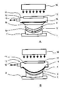
Figures 1A and 1 B are schematic views of an embodiment of the
process of the invention in which the coating is performed through a
flexible wafer urged against the lens blank fined and unpolished main
face using an inflatable membrane apparatus.
Figure 1A shows the lens blank 1, flexible wafer 4 and inflatable
membrane 14 before pressurization and inflatation of the membrane,
whereas figure 1 B shows the same after pressurization and inflatation of
the membrane 14.
Although, the following description will be made in connection with
UV curing of the liquid coating composition, similar apparatus and
process can be used with a thermally curable coating composition.
Referring to figure 1A, a lens blank 1, for example a toric lens
blank, is placed in a lens blank support 2 with its fine but unpolished
geometrically defined main face 1 a facing outwardly.
A drop of UV curable liquid coating composition 3 is deposited at
the center of the geometrically defined main face 1 a of the lens blank 1.
A thin flexible wafer 4, for example a spheric wafer, is placed on
the coating composition.
The whole assembly is then placed in front of the membrane 14 of
an inflatable membrane apparatus 10.
CA 02552369 2006-06-30
WO 2005/063473 PCT/EP2004/014882
11
The inflatable membrane apparatus 10 comprises a fluid
accumulator 11, for example an air accumulator provided with fluid port
12, for example an air port connected to a pressurized fluid source (not
represented) for introducing pressurized fluid within the accumulator and
also evacuating pressurized fluid from the accumulator. The upper face
of the accumulator 10 comprises a light transparent portion 13, for
example a UV transparent quartz glass portion, whereas the lower face
of the accumulator 10 comprises a transparent inflatable membrane 14
in register with the transparent quartz glass 13.
As shown in figure 1A, the apparatus 10 further comprises a
guiding means 15 for laterally guiding the inflatable membrane 14 during
inflatation thereof. More specifically, this guiding means comprises a
trunconical part or funnel 15 projecting outwardly from the lower face of
the accumulator 10 and whose greater base is obturated by the inflatable
membrane 14 and whose smaller base is a circular opening having a
diameter at least equal to the base diameter of the flexible wafer 4 but
preferably slightly larger (up to 5 mm larger).
Typically, the funnel height will range from 10 to 50 mm,
preferably 10 to 25 mm, and will have a taper of 10 to 90°, preferably
30
to 50°.
Finally, a light source, for example a UV light source 16 is placed
behind the accumulator 10 in front of the transparent quartz plate 13.
Generally, the assembly comprising the lens blank holder 2, the
lens blank 1, the coating composition drop 3 and the flexible wafer 4 is
placed so that the rim of the flexible wafer 4 be within the plan of the rim
of the smaller base opening of funnel 15 or separated therefrom by a
distance up to 50 mm, preferably up to 20 mm.
As shown in figure 1 B, a pressurized fluid, such as pressurized
air, is introduced into the accumulator 11 from an external source (not
represented) through entrance 12. The pressure increase within the
accumulator, inflates the inflatable membrane 14 and, thanks to the
membrane guiding means 15, the membrane 14 uniformly urges the
flexible wafer 4 against the lens blank 1, while uniformly spreading the
coating composition 3.
The coating composition is then UV-cured.
CA 02552369 2006-06-30
WO 2005/063473 PCT/EP2004/014882
12
After completion of the curing step, the lens blank 1 is
disassembled from the holder 2 and the flexible wafer 4 is removed to
recover a lens blank 1 whose geometrically defined surface 1 a is
provided with a coating.
Of course, in case of a thermal curing process, light source and
transparent portion of the upper face of the accumulator are not needed.
In this case also, the inflatable membrane needs not to be
transparent. Otherwise, the apparatus remains the same.
Figures 2A and 2B are schematic views of another embodiment of
the process in which the inflatable membrane 14 of the apparatus 10 is
directly used as the flexible part for uniformly spreading the UV curable
liquid coating composition 3 on the fined but unpolished main face 1 a of
the lens blank 1.
Otherwise, the coating process proceeds in a similar manner as
disclosed in connection with Figures 1A and 1B.
In the description and the following examples the surface
roughness Sq of the fined but unpolished main face of the lens blank is
as follows
Sq : Quadratic mean of the deviations from the mean
1 N M 2
Zx,y
x=1 y=1
Computes the efficient value for the amplitudes of the surfaces
(RMS). This parameter is included in the EUR 15178 EN report
(Commission of the European Communities) Stout et AI 1993: The
development of methods for the characterisation of roughness in three
dimensions.
The roughness (Sq) is measured by P-10 Long Scan of KLA-
Tencor.
The measurement condition was under 2 p,m tip 1 mg force 10
scans 500 ~,m long 2000 data points.
In the description and the following examples,
CA 02552369 2006-06-30
WO 2005/063473 PCT/EP2004/014882
13'
N
1
- N ~ (Zn)z
n=1
Rq is determined as follows:
A TAYLOR HOBSON FTS (Form Talysurf Series 2)
profilometer/roughness measuring system is advantageously used to
determined the root-mean-square profile height Rq (2DRq) of the surface
(also referred as roughness Rq before).
The system includes a laser head (product reference 112/2033
541, for example) and a 70 mm long feeler (product reference 11211836)
having a 2 mm radius spherical/conical head.
The system measures a two-dimensional profile in the chosen
section plane to obtain a curve Z = f(x). In this example the profile is
acquired over a distance of 20 mm.
Various surface characteristics can be extracted from this profile,
in particular its shape, undulation and roughness.
Accordingly, to determine Rq, the profile is subject to two different ,
processes, namely shape extraction and filtering, which corresponds to
mean line extraction.
The various steps for determining a parameter Rq of this kind are
as follows:
- acquisition of the profile Z = f(x),
- shape extraction,
- filtering (mean line extraction), and
- determination of parameter Rq.
The profile acquisition step consists in moving the stylus of the
aforementioned system over the surface of the lens in question, to store
the altitudes Z of the surface as a function of the displacement x.
In the shape extraction step, the profile obtained in the previous
step is related to an ideal sphere, i.e. a sphere with minimum profile
differences relative to that sphere. The mode chosen here is the LS arc
mode (best circular arc extraction).
This provides a curve representative of the characteristics of the
profile of the surface in terms of undulation and roughness.
CA 02552369 2006-06-30
WO 2005/063473 PCT/EP2004/014882
14
The filtering step retains only defects corresponding to certain
wavelengths. In this example, the aim is to exclude undulations, a form
of defect with wavelengths higher than the wavelengths of defects due to
roughness. Here the filter is of the Gaussian type and the cut-off used is
0.25 mm.
Rq is determined from the curve obtained using the following
equation:
N
1
Ra - N ~ (Zn)z
n=1
where Zn is, for each point, the algebraic difference Z relative to the
mean line calculated during filtering.
The grinding and fining process used in the examples is V-95
grinding followed by fining with a 15 ~,m pad (from 3M).
- V-95 is a computer controlled grinding machine from LOH company
with 3D disk cutter. The grinding time is about 1 to 2 minutes;
- Haze has been measured by Haze-Gard Plus made by BYK Gardner;
- Inspection with an arc lamp is carried out by using a BT X 75/LIS //
Lamp made by Bulbtronics Inc. the light from the above lamp is
directed towards the lens and the reflected light is projected on a
screen. The image of the lens on the screen is visually inspected in
order to see if there are fining lines.
EXAMPLE 1
A semi-finished lens SF lens made of diethyleneglyco! bis-allyl
carbonate copolymer (CR-39~) was generated by V-95 and fined with
15 g.m pad to a -1.25 power lens (back curvature 5.0 base, diameter 70
mm) without polishing. Fining process is done with LOH Toro-X-S/SL
fining machine using a 15 p.m pad made by 3M. The fining time is about
1 to 2 minutes. The lens was then washed with water and soap and
coated with an abrasion-resistant coating by the process of the invention
using a thin flexible wafer and the inflatable membrane apparatus as
described in connecfiion with the figures.
5 drops of the liquid coating composition (0.12 g in total) are
deposited on the fined main face of the lens. The thin flexible wafer is
carefully placed on the liquid coating composition drops.
CA 02552369 2006-06-30
WO 2005/063473 PCT/EP2004/014882
The resulting assembly is then placed in front of the inflatable
membrane of the air accumulator and air is introduced up to a pressure
of 84 kPa (12 Psi) so that the liquid coating composition is spread out in
the entire fined main face of the lens.
5 The coating composition is then UV cured for 30 seconds using a
UV lamp with high intensity 145 mW/cm2 and wavelength from 330 to
490 nm. After separation, there is obtained a clear coating layer on the
lens without any visible fine lines by illumination with an arc lamp.
10 UV curable liauid coating composition, in weight
- UVR-6110 (3,4-epoxycyclohexyl
methyl-3,4-epoxycyclohexane carboxylate)13
- GE 21 (1,4-butanediol diglycidyl 30.29
ether)
15 - HDODA (hexane diol diacrylate) 10.85
- SR-399 (dipentaerythritol pentaacrylate)30.36
- SR 230 (diethyleneglycol diacrylate)7.01
- IBOA (isobornyl acrylate) 2.29
- UVI 6974 (cationic photoinoitiator)5.25
- IRGACURE 500 (free radical initiator)0.82
- SLF-18 (hydrocarbon base surfactant)0.1
Flexible wafer
A wafer made of polycarbonate with 0.6 mm thick piano
sphere
shape having a 5.50 base curve and mm diameter. The wafer
a 68 is
made by injection molding and is
precoated with a release and protective
coating solution.
EXAMPLE 2
Example 1 is reproduced except using a liquid coating composition of
refractive index nD =1.532
This liquid composition has the following formulation, in weight
- EPON 228 (bisphenol A epoxy resin) 60
- GE 21 (1,4-butanediol diglycidyl ether) 40
- IRGACURE 552 (photoinitiator) 4 phr
- lTX (sensitizer) 0.2 phr
CA 02552369 2006-06-30
WO 2005/063473 PCT/EP2004/014882
16
COMPARATIVE EXAMPLE 1
Example 1 is reproduced except using spin coating process and
cured by conveyor UV with the same coating solution. The results
showed that even a much thick coating layer on a fining lens (60 x Rq of
surface roughness) by spin could not cover the fining mark. The spin
coating was done by Headway Spin Coat and spinning speed was 600
rpm for 12 seconds and 2000 trm for 4 seconds. Thereafter, curing was
effected using a Fusion UV conveyor at 9 mm H bulb, 692 mW/cm2 at
350 nm.
COMPARATIVE EXAMPLE 2
Example 1 is reproduced except using high index ( nD =1.57 )
coating solution. This coating solution has the following formulation, in
weight
- Diethyleneglycol diacrylate 30
- Ethoxylated-8 bisphenol A diacrylate 30
- Bis(2-methacryloylthioethyl) sulfide 40
- IRGACURE 819 (photoinitiator) 3 phr
EXAMPLE 3
A PC SF lens was generated by V-95 and fined with 15 ~,m pad to
-2.00 power lens (back curve = 5.0 base) without polishing. The lens
was then washed with soap and water and the same coating solution as
in comparative example 2 is applied as in Example 1.
COMPARATIVE EXAMPLE 3
Example 3 is reproduced except using the same low index
(nD =1.518 ) coating solution as in example 1.
COMPARATIVE EXAMPLE 4
Example 3 is reproduced except using a flow coating method.
Flow coating is similar to dip coating which still cannot cover the fining
lines in arc lamp even though the coating thickness is higher than 10 x
Sq of surface roughness and the haze level is low.
CA 02552369 2006-06-30
WO 2005/063473 PCT/EP2004/014882
17
In that example, 5g of coating liquid was manually smoothly
applied on the fined lens surface and turned around to let the liquid wet
the whole surface. Then, the coating was cured using a Fusion UV
conveyor at 9 mm H bulb, 692 mW/cm2 at 350 nm.
EXAMPLE 4
A CR-39~ SF lens was generated by V-95 and fined with 15 p,m
pad to - 1.25 power lens without polishing. The lens was then tinted in
BPI black bath, commercially available, at 95°C for 15 min. After
that, the
tinted CR-39 lens was press coated by the same method as Ex. 1 with
the commercial UV curable coating solution (HT-1000 from GERBER
COBURN Inc.). The obtained lens has very good uniform color and very
good transmission and low haze level. There is no any fining line seen in
arc lamp after press coating.
EXAMPLE 5
A CR-39 SF~ lens was generated by V-95 and fined with 15 ~,m
pad to -1.25 lens without polish. After that, it was press coated by the
same method as in example 1 with the commercial UV curable coating
solution (HT-1000 from Gerber Coburn Inc.). The obtained lens has very
good transmission and low haze level. There is no any fining line seen in
arc lamp after press coating. The lens was then coated with an anti
reflective coating by using BAK 760 vacuum machine. It has the same
properties as a commercial hard multicoated CR-39~ lens made using a
polishing step.
35
CA 02552369 2006-06-30
WO 2005/063473 PCT/EP2004/014882
TABLE 1
Ex. Lens Fining SurfaceHaze CoatingCoatingThickneHaze Fining
materiprocessroughnebeforerefractivprocessss after mark
of in
als ss coatinga coatingcoatingarc
(Rq) index
ri25 lamp
Ex. CR-39V-95 0.378789.8 1.518Press - 0.37 No
1 + 15 5
~m
~m fining[gm] coating
(2 min)
Ex. CR-39V-95 0.394389.8 1,532Press - 1.50 No
2 + 15 5
gm
um [gym] coating
fining
(2
min)
Com.CR-39V-95 0.375889.8 1.518Spin - 0.35 Yes
+ 15 25
gm
1 gm [wm] coating
fining
(2
min)
Com.CR-39V-95 0.383189.8 1.57 Press - 6.70 Yes
+ 15
2 ~m [gm] coating
fining
(2
min)
Ex. PC V-95 0.208983.1 1.57 Press - 1.17 No
3 + 15
g,m [gm] coating
fining
(2
min)
Com.PC V-95 0,218183.1 1.518Spin - 2.40 Yes
+ 15
3 gm [g.m] coating
fining
(2
min)
Com.PC V-95 0.216383.1 1.57 Flow > 1.15 Yes
+ 15 25
g.m
4 wm [pm] coating
fining
(2
min)
CA 02552369 2006-06-30
WO 2005/063473 PCT/EP2004/014882
19
Thickness ofi coating layers was measured by using cross-
sectioned samples in microscopy of Nikon Optiphot-2 with 600 x of Epi
illumination.
EXAMPLE 6
Example 1 was reproduced by using a very low viscosity (7cps)
coating solution consisting of, by weight, 89% diethyleneglycol
dimethacrylate and 11 % bis-2-[(meth)acryloylthioethyl] sulfide (BMTES),
with 3 phr photoinitiator/CGI-819 (Irgacure 819 from Ciba-Geigy:
bis(2,4,6-trimethylbenzoyl)-phenylphosphineoxide). The refractive index
np (25°C) of the coating solution was 1.472. The observed coating
thickness after curing is around 1-2 micrometers. There is no fining mark
seen in the arc lamp after press coating although the coating thickness
is very thin.
EXAMPLE 7
A 20 micrometers pad fined but not polished glass mould with
surfaced roughness of Sq=0.58 pm was press coated by the same
method as in example 1 with the commercial UV curable coating
solution (HT-1000). The obtained glass mould has very good
transmission and low haze level. There is no any fiining line seen in the
arc lamp after press coating.
COMPARATIVE EXAMPLE 5
The same fined but not polished glass mould as in Example 7
was spin coated using Ultra Optics coating machine with HT-1000 UV
curable coating solution. The obtained glass has a lot of fining lines
seen in the arc lamp.