Note: Descriptions are shown in the official language in which they were submitted.
CA 02552497 2006-06-30
WO 2005/068148 PCT/US2004/043471
TRANSFER MOLD, PRODUCTION METHOD THEREOF AND
PRODUCTION METHOD OF FINE STRUCTURE
Background
A plasma display panels (PDP) have drawn an increasing attention in recent
years
as a flat panel display that is thin and has a large screen. Such panels are
being used for
business purposes and as wall-hung television sets.
A plasma display panel (PDP) generally contains a large number of fine
discharge
display cells. Each discharge display cell is encompassed and defined by a
pair of glass
substrates spaced apart from each other with barrier partitions (also called
"barrier ribs")
between the glass substrates. The burner ribs are generally composed of a fine
structure of
ceramic material. When a single set of parallel burner ribs are employed, the
burner ribs
form a striped pattern. In such embodiment, the discharge display cells are
the trough
depressions between the burner ribs. Alternatively, the barrier partitions may
have a grid
pattern.
Several methods of forming a barrier ribs are known. See for example JP 9-
283017 and JP 10-134705.
Brief Description of the Drawings
Fig. 1 is a sectional view showing an example of a PDP.
Fig. 2 is a perspective view showing a PDP back plate used in the PDP shown in
Fig. 1.
Fig. 3 is a perspective view showing a transfer mold according to the
invention.
Fig. 4 is a sectional view of the mold taken along a line IV - IV in Fig. 3.
Fig. SA-SC is a sectional view showing, in sequence, a production method of a
transfer mold according to the invention.
Fig. 6 is a perspective view of a master mold used as a matrix in the
production
method shown in Fig. 5.
Fig. 7 is a flowchart showing a basic concept of a production method of a fine
structure according to the invention.
Fig. 8A-8C is a sectional view showing, in sequence, a production method of a
1
CA 02552497 2006-06-30
WO 2005/068148 PCT/US2004/043471
flexible mold used as a second transfer mold in a production of a fine
structure by using
the transfer mold of the invention as a first transfer mold.
Fig. 9A-9C is a sectional view showing, in sequence, a production method of a
fine
structure by using the flexible mold produced by the method shown in Fig. 8.
Summary of the Invention
When a the silicone sheet is heat pressed during the production process of the
mold, as described in JP 10-134705, dimensional changes occur. Accordingly,
industry
would find advantages in molds and methods of making such molds having
improved
dimensional accuracy.
In one aspect the invention relates to a transfer mold comprising a transfer
pattern
layer having a positive protrusion pattern surface comprised of a polymeric
material,
supported by a base layer comprised of a different material than the transfer
pattern layer.
In another aspect, the invention relates to a method of producing a transfer
mold
comprising providing a base substrate, forming a transfer pattern layer having
a positive
protrusion pattern from a curable polymeric composition wherein the curable
composition
comprises a different material than the base substrate, and curing the
transfer pattern layer
is preferably cured at ambient temperature. The transfer pattern layer is
preferably formed
from a master mold having on a surface thereof a negative groove pattern such
as by
applying the curable composition onto the negative groove pattern surface of
the master
mold and stacking the base substrate onto the master mold.
In other aspect invention also relates to methods of producing positive and
negative replications of the transfer mold as well as methods of producing a
fine structure
(e.g. plasma barrier ribs) from a molded replica of the transfer mold.
Each of these aspects may include any one or combination of various features
such
as described as follows. The base preferably comprises a material having a
Young's
modulus ranging from 1 GPa to 250 Gpa and more preferably from100 GPa to 250
GPa.
Metal materials such as stainless steel, copper and alloys thereof are
preferred base
material. The transfer pattern layer typically has a thickness ranging from
0.005 mm to 10
mm; whereas the thickness of the base ranges from 0.1 mm to 5 mm. The
protrusion
pattern of the transfer pattern layer may comprise a pattern suitable for a
plasma display
panel such as a parallel rib pattern or grid pattern. The transfer pattern
layer preferably
2
CA 02552497 2006-06-30
WO 2005/068148 PCT/US2004/043471
comprises a composition curable at ambient temperature such as silicone rubber
and (e.g.
polyester) polyurethane. A primer layer may be disposed between the base layer
and the
transfer pattern layer.
Detailed Description of Preferred Embodiments
The invention relates to a transfer mold, its production method and a
production
method of a fine structure. In the description that follows, embodiments of
the invention
will be explained in detail with respect to the production of a PDP rib as a
typical example
of the fme structure. The invention is surmised useful for other structures
and thus is not
limited to the production of the PDP rib.
With reference to Fig 1 and Fig. 2, each discharge display cell 56 is
encompassed
and defined by a pair of glass substrate opposing each other with a spacing
between them,
that is, a front glass substrate 61 and a back glass substrate 51, and fine
structure ribs
(barrier ribs; also called "partitions" or "barriers") 54. The front glass
substrate 61 has
1 S thereon transparent electrodes 63 consisting of scanning electrodes and
sustaining
electrodes, a transparent dielectric layer 62 and a transparent protective
layer 64. The
back glass substrate 51 has thereon address electrodes 53 and a dielectric
layer 52. The
display electrode 63 having the scanning electrode and the sustaining
electrode and the
address electrode 53 intersect each other and are arranged in a predetermined
spacing,
respectively. Each discharge display cell 56 has a phosphor layer 55 on its
inner wall and
contains a rare gas (such as Ne-Xe gas) sealed therein so that self emission
light display
can be made due to plasma discharge between the electrodes.
The ribs 54 of the PDP are arranged on the back surface glass substrate 51 and
constitute the back surface plate for the PDP. The gap of the ribs 54 (cell
pitch) C varies
with a screen size but is generally at least about 150 and typically no
greater than about
400 p,m.
Generally, the ribs satisfy two criteria, that is, "they are free from defects
such as
mixture of bubbles and deformation" and "they have high pitch accuracy". As to
pitch
accuracy, the ribs are arranged at predetermined positions during molding with
minimal
positioning errors to address electrodes. The positioning error is no greater
than one third
of the average pitch. The positioning error is typically less than 25% of the
average pitch,
preferably less than 20% of the average pitch, more preferably less than 15%,
and even
CA 02552497 2006-06-30
WO 2005/068148 PCT/US2004/043471
more preferably less than 10% of the average pitch.
As the screen size has becomes larger, pitch accuracy of the ribs become
increasingly important. When the ribs 54 are taken into consideration as a
whole, the total
pitch R of the ribs 54 (distance between ribs 54 at both ends; though the
drawing shows
only five ribs, about 3,000 ribs exist generally) typically have a dimensional
accuracy
within 10 pm to 30 p,m.
It is generally advantageous to mold the ribs by use of a flexible mold
including a
support and a shape-imparting layer with a groove pattern supported by the
support. In the
case of such a molding method, the desired dimensional accuracy can be
achieved.
The transfer mold according to the invention is particularly advantageous for
forming grid-like ribs for the PDP for the following reasons.
The number of discharge display cells is as great as two to three millions in
the
case of a large-sized PDP of the 42-inch class. Therefore, an extremely long
period of
time is necessary for a machining process of the mold. In the case of a grid-
like rib having
3,000 longitudinal ribs and 1,000 transverse ribs, for example, 3,000,000
(3,000 x 1,000)
discharge cells are bored to fabricate a master mold having a grid-like
protrusion pattern.
Instead, when a design is so changed as to process the grid-like groove
pattern to the
master mold according to the invention, only 4,000 (3,000 + 1,000) grooves
need be
linearly cut and formed. In other words, the invention can reduce the
machining time of
the master mold and thereby the cost. By use of a transfer mold as the mold
for producing
the fine structure, the invention eliminates the necessity for producing a
large number of
master molds.
For the sake of explanation, the term "grid-like pattern" used for explaining
the
grid-like ribs means not only the typical grid-like pattern that will be
hereinafter explained
with reference to Figs. 4 and 6 but also similar pattern having a structure
approximate to
the grid. Examples of the patterns effective for executing the invention
include a meander
pattern, a waffle pattern, a diamond pattern, and so forth.
As will be hereinafter explained in detail, the illustrated PDP ribs can be
produced
advantageously by the steps of forming a transfer mold by use of a master mold
having a
shape and a size corresponding to those of the rib as a mold, duplicating a
flexible mold
from the transfer mold, that is, by forming the flexible mold by using the
transfer mold as
a substantial matrix. When the flexible mold is used, the intended PDP ribs
can be
4
CA 02552497 2006-06-30
WO 2005/068148 PCT/US2004/043471
produced easily and highly accurately.
First, the invention resides in a mold for transfer (hereinafter merely called
"transfer mold") that is used for transfernng a fine structure pattern in the
production of a
fine structure. Fig. 3 is a perspective view showing a preferred form of the
transfer mold
according to the invention and Fig. 4 is a sectional view taken along a line
IV - IV of Fig.
3. As shown in these drawings, the transfer mold 10 includes a base 11 and a
transfer
pattern layer 12 supported on the back thereof by the base 11 and having on
the surface
thereof a positive protrusion pattern 14 having a shape and a size
corresponding to those of
the fine structure pattern (grid-like pattern in the drawings).
The transfer mold 10 according to the invention has a transfer pattern layer
12 is
formed of a cured two-component composition. The transfer pattern layer is
preferably
formed from a room temperature curable composition such as a silicone rubber
or
polyurethane.
The fine structure produced by use of the transfer mold shown in the drawings
is
not particularly limited. A preferred fine structure pattern in the practice
of the invention
is the fine structure pattern for the PDP ribs as described above. The
positive protrusion
pattern of the transfer mold is generally a straight pattern constituted by a
plurality of
protrusion portions arranged substantially parallel to one another with
predetermined gaps
among them, or a grid-like pattern 14 constituted by a plurality of protrusion
patterns
arranged substantially parallel to one another while intersecting one another
with
predetermined gaps among them as shown in Fig. 3. The grid-like patterns 14
adjacent to
one another define a cavity 15 corresponding to a discharge display cell of
the PDP panel,
for example. Even when the fine structure pattern has a complicated pattern
typified by
the grid-like pattern, the transfer mold according to the invention typically
exhibits a
relatively low peeling force when the transfer mold is peeled from the master
mold. The
transfer mold according to the invention exhibits less breakage of the
protrusion portions.
CA 02552497 2006-06-30
WO 2005/068148 PCT/US2004/043471
In the transfer mold described herein, the base is preferably comprised of a
different material that the transfer layer. The base is preferably formed of a
hard material
having a Young's modulus of at least 1 GPa and typically no greater than 300
GPa. The
Young's modulus (i.e. modulus of longitudinal elasticity) of various materials
is known
and is described in the literature such as in the JSME Mechanical Engineers'
Handbook,
Japan Society of Mechanical Engineers, 1984. Preferably, the base has a
Young's modulus
of at least about 100 GPa and typically no greater than about 220 GPa Such a
hard
material is preferred for maintaining the high dimensional accuracy of the
master mold
when the mold for use in transfer (transfer mold) is produced from the master
mold. In
other words, when a molding material of the transfer pattern layer is applied
to and cured
on the master mold, it is generally difficult to precisely keep dimensional
accuracy of the
resulting transfer pattern because the molding material of the transfer
pattern layer
undergoes shrinkage upon curing. When a hard material having a high elastic
modulus is
employed for the base, the invention can provide high dimensional accuracy.
The hard material suitable for the base includes a broad range of metals and
plastic
materials. Metal materials are particularly useful. Examples of the suitable
metal
materials include stainless steel (e.g. Young's modulus of about 200 Gpa),
copper (e.g.
Young's modulus of about 130 GPa), and brass (e.g. Young's modulus of about
100 GPa).
The metal materials may be used either individually or in the form of an
alloy, whenever
desired. Plastic materials having the desired young's modulus include for
example nylon
(e.g. Young's modulus ranging from about 1.2 to 2.9 GPa), polystyrene (e.g.
Young's
modulus of about 2.7 to about 4.2 GPa), and certain polyethylene materials.
The base is generally used in the form of a sheet or plate made of a single
hard
material but may be used in the form of a composite or laminate (stacked
body), whenever
desired. The thickness of the base can be changed in a broad range depending
on the
specification of the transfer mold but is generally within the range of about
0.1 to 5 mm
and more preferably within the range of about 0.5 to 3 mm. When the thickness
of the
base is smaller than 0.1 mm, handling property of the transfer mold drops and
it becomes
difficult to maintain the high dimensional accuracy of the mold. When a PET
film is used
as the base in place of a metal plate having a predetermined thickness, for
example, the
transfer mold becomes light in weight but it becomes difficult to keep high
dimensional
accuracy any more. When the thickness of the transfer mold exceeds 5 mm, on
the
6
CA 02552497 2006-06-30
WO 2005/068148 PCT/US2004/043471
contrary, the handling property of the transfer mold drops because the weight
increases.
The transfer pattern layer, a back surface of which is supported by the base,
is
formed of a curable composition that is preferably curable at room
temperature. In at least
some embodiments, the curable composition is preferably a (e.g. two-component)
silicon
rubber or polyurethane. When the transfer pattern layer is formed from a room
temperature curable composition, the substrate and the master mold need not be
heat-
treated unlike thermosetting resins. Therefore, deformation resulting from
heating and the
drop of dimensional accuracy resulting from this deformation can be avoided.
It is also
surmised to form the transfer pattern layer by use of a photo-curable resin
and a moisture-
curable resin. However, it is appreciated that it is more difficult to
sufficiently cure such
compositions while the resin is sandwiched between the master mold and the
substrate.
The transfer pattern layer composition preferably has low surface energy and
flexibility. Consequently, the peeling force of removing the transfer mold
(first transfer
mold) from the master mold as well as the peeling work of removing the
transfer mold
after molding the fine structure (second transfer mold from the first transfer
mold) is
relatively low. In at least some preferred embodiments, the 180° peel
force after
conditioning for 24 hours of removal is less than 5 kgf/100mm and more
preferably less
than 1 kgf/100mm (e.g. less than 0.5 kgf/100mm.
The (e.g. room temperature) curable transfer pattern layer composition can
generally be cured within a few hours. Therefore, the transfer mold can be
produced in a
few hours. Because the transfer pattern layer has the strength capable of
withstanding the
repetition of use, the transfer mold thus produced can be used (e.g. as a
substantial matrix)
in place of the conventional master mold. This reduces processing time in
comparison to
producing the mold by direct machining.
The room temperature-curable silicone rubbers can be cured at ambient
temperature (about 20 to 25°C), and are generally classified into one-
component type
products curable upon reacting with the moisture in air and two-component type
products
in which a main component and a curing agent are mixed in a predetermined
ratio at the
time of use and which can be cured upon reaction therebetween. Various curable
silicone
rubber compositions can be employed so long as it can form a desired transfer
pattern
layer. In one embodiment, the room temperature-curable silicone rubber
comprises at
least one (e.g. difunctional) organopolysiloxane, a cross linking agent and a
catalyst.
7
CA 02552497 2006-06-30
WO 2005/068148 PCT/US2004/043471
The organopolysiloxane can be represented by the following formula (I):
Ri R3
X~-(~SiO-~,.Si XZ (Formula 1)
R2 Ra
wherein R~ to R4 are each independently hydrogen atom or an organic group,
preferably a
substituted or unsubstituted alkyl group such as a methyl group or an ethyl
group;
X1 and Xz are each independently a reactive group, preferably a functional
group such as a
hydroxyl group; and
n is an integer of about 100 to 1,000.
The cross linking agent is preferably a silane or polysiloxane having at least
two
functional groups such as a hydroxyl groups per molecule, for example.
A conventional catalyst such as a tin compound, amine, a platinum compound,
etc,
is used as the catalyst.
These components may be blended in various ratios. For example, the blend
ratio
of the organopolysiloxane and the cross linking agent is generally within the
range of
about 100:0.5 to 100:10 (condensation reaction type silicone rubber) or about
100:3 to
100:100 (addition reaction type silicone rubber).
The silicone rubber may optionally contain various additives, are desired.
Examples of the suitable additives include reaction inhibitors, release agent,
a mold
release accelerator, a fluidization adjuster, and so forth. Specifically, the
two-component
type room temperature-curable silicone rubber is commercially available, for
example,
from GE Toshiba Silicone under the trade designations "TSE3503", "TSE350",
"TSE3504", "TSE3502", "XE12-246", "TSE3508", "XE12-A4001", "TSE3562",
"TSE3453", "TSE3453T", "TSE3455T", "TSE3456T", "TSE3457T" and "TSE3450".
Other two-component type room temperature-curable silicone rubber is
commercially
available from Toray Dow Corning Silicone under the trade designations
"SH9550RTV",
"SH9551RTV", "SH9552RTV", "SH9555RTV", "SH9556RTV" and "SH9557RTV". In
addition to the above products, two-component type room temperature-curable
silicone
rubbers are also commercially available from Sumitomo 3M Ltd. under the trade
8
CA 02552497 2006-06-30
WO 2005/068148 PCT/US2004/043471
designations "6160", "7322H" and "0425H". Details concerning two-component
type
room temperature-curable silicone rubber is described in Kumada and Wada,
"Recent
Application Technologies of Silicone", published on February 26, 1987 by
Kabushiki
Kaisha CMC.
Various polyurethanes are suitable for the transfer pattern layer.
Polyurethanes are
generally prepared by the reaction of at least hydroxyl containing material
with at least
one polyisocyanate. "Polyisocyanate" means any organic compound that has two
or more
reactive isocyanate (--NCO) groups in a single molecule such as diisocyanates,
triisocyanates, tetraisocyanates, etc., and mixtures thereof. Cyclic and/or
linear
polyisocyanate molecules may usefully be employed.
Various suitable polyisocyanates are available from Mitsui-Takeda Chemical,
including toluene diisocyanate (TDI) adducts of the "Takenate D100" series
(such as D-
lOlA, D-102, D-103, D-103H, D-103M2, D-104)"; TDI polymeric isocyanates of the
"Takenate D200" series (such as D-204, D-204EA, D-212, D-212L, D-212M6, D-262;
D-
215, D-217, D-218, D-219, D-268, D-251 D); as well as xylylene diisocyanate
(XDI),
isophoronediisocyanate ( IPDI), hexamethylene diisocyanate (HDI) adducts of
the
"Takenate D110 series( D-110N, D-120N, D-127N, D-140N, D-160N, D-165N, D-170N,
D-170HN, D-172N, D-177N, D-178N)".
Although the hydroxyl group-containing material is typically a polyol
comprising
two or more hydroxyl groups, material comprising a single hydroxyl group may
be
employed alone or in combination with a polyol. A variety of polyols can be
utilized in
the preparation of the modified isocyanate component. Suitable polyols include
polyester
polyols, polyether polyols, polydiene polyols, hydrogenated polydiene polyols,
polycarbonate polyols, and hydrocarbon polyols. Although the polyol may
contain more
than two hydroxyl groups, in at least some embodiments, the polyol is
preferably
difunctional.
Various polyester polyols are available from Mitsui-Takeda Chemical such as
polyester polyols of the "Takelec U" series (such as U-21, U-24, U-25, U-27, U-
53, U253,
U-502, U-118A); acrylic polyols of the "Takelec UA" series (such as UA-702, UA-
902,
UA-906); and polyurethane polyols of the "Takelec E" series (such asE-158, E-
550, E-
SS1T, E-553, E-900).
The transfer pattern layer formed upon curing of the (e.g. room temperature)
9
CA 02552497 2006-06-30
WO 2005/068148 PCT/US2004/043471
curable composition (also called "precursor of the transfer pattern layer")
has sufficient
strength and other properties and can be as such used as a shape-imparting
molding
member of the transfer mold. The curing can be carried out under various
conditions. It is
preferred however, the composition of the transfer layer cures ambient
temperatures,
ranging from 25°C to 100°C. For example, the silicone rubber
transfer layer may be cured
at 25°C for about 16 hours or at 100°C for about 2 hours.
A primer layer may be optionally provided between the transfer layer and the
base
to improve the adhesion of these layers to each other. Various primer
compositions are
known in the art suitable for this purpose. In the case of silicone rubber
transfer layers,
polyalkylsiloxane, polyalkoxysilane, and mixture thereof provide suitable
primer layers.
In the case of polyurethane, isocyanate or hydroxy functional material
provided suitable
primers.
The thickness of the transfer pattern layer can vary but is generally at least
about
0.005 mm and typically no greater than 10 mm. Preferably the transfer pattern
layer is at
least about 20 ~.m and preferably no greater than 200 p,m. When the thickness
of the
transfer pattern layer is smaller than 0,005 mm, it becomes difficult to
impart the positive
protrusion pattern to the surface of the layer. When the thickness of the
transfer pattern
layer exceeds 10 mm the material costs increase.
The positive protrusion transfer mold employs a master mold having on its
surface
a negative groove pattern (recess pattern) having a shape and a size
corresponding to those
of the fine structure pattern of the fine structure. Therefore, the transfer
mold provides
also the effect that machining of the master mold can be made easily and
within a
relatively short time. The grid-like recess pattern of the master mold can be
machined into
a metal drum. In the case of PDP the master is typically fabricated by
machining grooves
into a flat planar substrate. The master mold preferably comprises a
machinable metal
such as brass, copper, aluminum, beryllium-copper alloys, as well as
electrolytic and
electroless nickel-phosphor alloys. When a fine structure (for example, PDP
rib) is
directly produced by transfer from a master mold having a recess pattern on
its surface as
has been made in the prior art, a problem such as breakage of protrusion
portions (such as
ribs) occurs. In contrast, because the invention uses the transfer mold having
a specific
structure, the invention can avoid such a problem. In short, the master mold
having a grid-
CA 02552497 2006-06-30
WO 2005/068148 PCT/US2004/043471
like recess pattern can easily be processed and the grid-like ribs can be
formed without
inviting the rib defects.
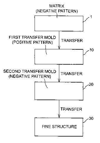
The fine structure, is preferably produced by the following steps (e.g. in
sequence)
as will be hereinafter explained with reference to Fig. 7:
production of a matrix (master mold) having a grid-like recess pattern;
production of a transfer mold (first transfer mold) having a grid-like
protrusion
pattern;
production of a mold (second transfer mold), for forming a fine structure,
having a
grid-like recess pattern; and
production of a fine structure.
Since this production process involves a large number of process steps, there
are
increased opportunities to introduce dimensional accuracy errors. Because the
invention
employs the transfer mold having a specific structure as the first transfer
mold as
described above, however, the invention can easily keep dimensional accuracy.
This
effect can be further improved by use of a flexible mold to be next explained
as the second
transfer mold.
The transfer mold according to the invention can be produced by various
methods
but is preferably produced by the method comprising the following steps:
forming a transfer pattern layer having on its surface a positive pattern
(positive
protrusion pattern) having a shape and a size corresponding to those of the
fine structure
pattern of the intended fine structure from a (e.g. two-component room
temperature-
curable composition (e.g. silicone rubber or polyurethane); and
supporting the back of the transfer pattern layer by use of a base, preferably
formed
of a hard material having a high elastic modulus.
Further, in the practice of this production method, it is preferred to use a
master
mold having on its surface a negative groove pattern having a shape and a size
corresponding to those of the fine structure pattern of the fine structure as
a matrix, to
transfer the groove pattern of the master mold and to form the positive
protrusion pattern
of the transfer pattern layer.
In greater detail, the transfer mold according to the invention can be
produced by
conducting, in sequence, the following steps:
applying a two-component (e.g. room temperature) curable composition (e.g.
11
CA 02552497 2006-06-30
WO 2005/068148 PCT/US2004/043471
silicone rubber or polyurethane) at a predetermined thickness onto a surface
of a master
mold to thereby form a precursor layer of the transfer pattern layer described
above;
stacking the base onto the master mold to thereby form a stacked body
including.
the master mold, the precursor of the transfer pattern layer and the base;
curing the composition; and
releasing the transfer pattern layer formed by curing of the composition,
together
with the base, from the master mold.
Fig. S typically shows a production method of a transfer mold according to the
invention.
First, a master mold 1 that is shown by a perspective view in Fig. 6 and by a
sectional view taken along a line V(A) - V(A) in Fig. 6 is prepared. The
master mold 1 is
used as the matrix when the transfer mold 10 according to the invention shown
in Figs. 3
and 4 is produced, and is formed of a flat sheet of brass, for example. The
master mold 1
has on its surface a negative groove pattern 4 having a shape and a size
corresponding to
those of the fine structure pattern of the fine structure. Incidentally, the
illustrated
example assumes the production of the grid-like PDP rib as the fine structure.
Therefore,
the negative groove pattern 4 is the grid-like groove pattern as shown in Fig.
6. The
negative groove pattern 4 has a more complicated arrangement than a stripe
pattern, but
can be machined far easier and within a shorter time than when the protrusion
pattern is
processed on the surface of the mold. The groove pattern can be formed by
providing fine
grooves on the surface of the mold with use of milling or discharge
processing. The shape
and the size of the negative groove pattern 4 can be easily understood from
the explanation
of the PDP rib already explained.
Next, as shown in Fig. 5(B), the (e.g. two-component room temperature) curable
composition (e.g. silicone rubber or polyurethane) 2 used as the precursor of
the transfer
pattern is applied at a predetermined film thickness onto the surface of the
master mold 1
so prepared. The illustrated example employs the method that applies the
curable
composition 2 to the surface of the master mold 1 and (e.g. serially) fills
the groove
patterns 4. However, other method may also be used. According to another
method, the
master mold and the base for the transfer mold are arranged with a
predetermined gap
between them and the curable composition is then charged into the gap. The
precursor
layer 2 of the transfer pattern layer can be formed at the predetermined
thickness by either
12
CA 02552497 2006-06-30
WO 2005/068148 PCT/US2004/043471
any of these methods. Alternatively, the curable composition 2 may be
processed (e.g.
partially cured) into a sheet and is then stacked on the pattern surface of
the master mold 1
so as to bring them into contact.
Subsequently, as shown in Fig. 5(C), the base 11 for the transfer mold is put
on the
master mold 1 and a stacked body including the master mold 1, the precursor
layer of the
transfer pattern layer and the base 11 is formed. Incidentally, the drawing
shows the
transfer pattern layer 12 formed by curing of the precursor. In other words,
when the
precursor is cured, the transfer mold 10 including the base 11 and the
transfer pattern layer
12 supported by the base 11 can be obtained. The curable composition is
generally
curable within a few hours.
Finally, the resulting transfer mold is released from the master mold, though
not
explained with reference to the drawing. The mold after mold releasing may be
cured at a
room temperature or at an elevated temperature, whenever necessary.
In another aspect, the invention relates to the production method of the fine
structure. This production method may be carried out through any production
process
steps so long as it uses the transfer mold according to the invention. The
production
method of the invention can be carried out particularly advantageously through
the
sequence shown in Fig. 7.
To begin with, the master mold having the negative pattern is prepared as the
matrix 1 as described above.
Next, the negative pattern of the matrix 1 is transferred (i.e. in reverse
image) in
the same way as described above to produce the transfer mold (first transfer
mold) 10
having the positive pattern.
The positive pattern of the first transfer mold 10 so produced is transferred
(i.e. in
reverse image) to produce the mold (second transfer mold) 20 for the fine
structure, having
the negative pattern. Incidentally, it is advantageous to produce the transfer
mold 20 as a
flexible mold as will be hereinafter explained. In the practice of the
invention, a large
number of second transfer molds 20 can be acquired with high accuracy from a
single first
transfer mold 10.
The production of the fine structure 30 having the positive pattern can be
carried
out by various methods that involve the transfer (i.e. in reverse image) of
the second
transfer mold 20.
13
CA 02552497 2006-06-30
WO 2005/068148 PCT/US2004/043471
In one preferred embodiment, the production method of the fme structure
according to the invention can be carried out advantageously by conducting, in
sequence,
the following steps:
applying the curable resin composition at a predetermined film thickness onto
the
pattern formation surface of the transfer mold and forming the precursor layer
of the
shape-imparting layer;
stacking further the support formed of the flexible film of the plastic
material on
the transfer mold and forming the stacked body including the mold, the
precursor layer of
the shape-imparting layer and the support;
curing the curable resin composition;
releasing the shape-imparting layer, formed by curing of the curable resin
composition, together with the support from the transfer mold and producing
the flexible
mold (second transfer mold) having the support and the shape-imparting layer
supported
on the back thereof by the support and having on its surface the negative
groove pattern
having the shape and the size corresponding to those of the fine structure
pattern;
applying the curable protrusion-forming material between the substrate and the
shape-imparting layer of the flexible mold to introduce the protrusion-forming
material
into the groove pattern of the mold;
curing the protrusion-forming material and producing the fine structure
including
the substrate and the protrusion pattern integrally bonded with the substrate;
and
removing the fme structure from the flexible mold.
In the production method of the fine structure according to the invention, the
shape
and construction of the second transfer mold having the negative groove
pattern are not
particularly limited, but the flexible mold can be advantageously used as
described above.
The flexible mold generally has a two-layered structure of the support and the
shape-
imparting layer supported by the support. However, the use of the support may
be omitted
provided that the shaping imparting layer itself has the function of the
support. The
flexible mold basically has the two-layered structure but an additional layer
or layers or
coating may be added, whenever necessary.
The form, the material and the thickness of the support in the flexible mold
are not
limited so long as it can support the shape-imparting layer and has sufficient
flexibility
and suitable hardness for securing flexibility of the mold. Generally,
however, a flexible
14
CA 02552497 2006-06-30
WO 2005/068148 PCT/US2004/043471
film of a plastic material (plastic film) can be advantageously used for the
support. The
plastic film is preferably transparent, having at least transparency
sufficient to transmit the
ultraviolet rays irradiated for forming the shape-imparting layer. Both the
support and the
shape-imparting layer are preferably transparent particularly in view of the
fact that the
PDP rib and other fine structures are produced from a photo-curable molding
material by
use of the resulting mold.
To control pitch accuracy of the groove portions of the flexible mold in the
plastic
film, it is preferred to select the plastic film that is by far harder than
the molding material
constituting the shape-imparting layer associated with the formation of the
groove
portions. In one embodiment, a photo-curable material such as a UV-curable
composition
is employed as the plastic material. Generally, the curing shrinkage ratio of
photo-curable
materials is a few percent. When the plastic film is hard, dimensional
accuracy of the
support can be kept even when the photo-curable material undergoes curing
shrinkage.
Consequently, pitch accuracy of the groove portions can be kept with high
accuracy.
When the plastic film is hard, pitch fluctuation can be limited to a low level
when the rib is
formed, and the hard plastic film is advantageously used from the aspects of
both
moldability and dimensional accuracy. When the plastic film is hard, further,
pitch
accuracy of the groove portions of the mold depends solely on the dimensional
change of
the plastic film. Therefore, to stably provide a mold having desired pitch
accuracy, it is
only necessary to conduct post-treatment so that the size of the plastic film
remains as
designed but does not appreciably change in the mold after production.
The hardness of the plastic film can be expressed by rigidity to tension, that
is, by
tensile strength. The tensile strength of the plastic film is generally about
5 kglmm2 as
reported by the Handbook of Chemistry and Physics, CRC Press. The tensile
strength is
preferably at least about 10 kg/mm2. When the tensile strength of the plastic
film is lower
than S kg/mm2, handling property drops when the resulting mold is taken out
from the
master mold or when the PDP rib is taken out from the resulting mold and
breakage and
tear axe likely to occur.
The plastic film is generally obtained by molding the plastic raw material
into a
sheet and is commercially available in the cut sheet form or in the roll form
wound into the
roll. Surface treatment may be applied to the plastic film to improve the
adhesion strength
of the shape-imparting layer to the plastic film, whenever necessary.
CA 02552497 2006-06-30
WO 2005/068148 PCT/US2004/043471
The shape-imparting layer preferably consists of a cured resin preferably
formed
by curing the UV-curable composition containing the acrylic monomer and/or
oligomer as
the main component. The method of forming the shape-imparting layer from the
UV-
curable composition is advantageous because an elongated heating furnace is
not
necessary for forming the shape-imparting layer and moreover, the cured resin
can be
obtained by curing the composition within a relatively short time.
Examples of the acrylic monomer suitable for forming the shape-imparting layer
include urethane acrylate, polyether acrylate, polyester acrylate, acrylamide,
acrylonitrile,
acrylic acid and acrylic acid ester, though they are not restrictive. Examples
of the acrylic
oligomer suitable for forming the shape-imparting layer include urethane
acrylate
oligomer, polyether acrylate oligomer, polyester acrylate oligomer and epoxy
acrylate
oligomer, though they are not restrictive. Particularly, acrylate and a
urethane acrylate
oligomer can provide a flexible and tough cured resin layer after curing, have
an extremely
high curing rate among the acrylates in general and can contribute to the
improvement of
1 S productivity of the mold. Furthermore, when these acrylic monomer and
oligomer are
used, the shape-imparting layer becomes optically transparent. Therefore, the
flexible
mold having such a shape-imparting layer makes it possible to use a photo-
curable
molding material when the PDP rib and other fme structures are produced.
The acrylic monomer and oligomer described above may be used individually or
in
an combination of two or more. A preferred result can be obtained when the
acrylic
monomer and/or oligomer is a mixture of urethane acrylate oligomer and mono-
functional
and/or bi-functional acryl monomer. The mixing ratio of the urethane acrylate
oligomer
and the acryl monomer in such a mixture can be changed in a broad range, but
it is
preferred to use about 20 to 80 wt-% of the urethane acrylate oligomer on the
basis of the
sum of the amounts of the oligomer and the monomer. Preferred resins
compositions for
the shape-imparting layer of the flexible mold are described in PCT patent
application
US04/26845 filed 8-18-2004; incorporated herein by reference.
The UV-curable composition may contain a photo-polymerization initiator and
other additives, whenever necessary. The photo-polymerization initiator
includes 2-
hydroxy-2-methyl-1-phenylpropane-1-one, for example. The photo-polymerization
initiator can be used in various amounts but is generally and preferably used
in an amount
of about 0.1 to about 10 wt-% on the basis of the sum of the acryl monomer
and/or
16
CA 02552497 2006-06-30
WO 2005/068148 PCT/US2004/043471
oligomer. When the amount of the photo-polymerization initiator is smaller
than 0.1 wt-
%, the curing reaction is remarkably retarded or sufficient curing cannot be
achieved.
When the amount of the photo-polymerization initiator exceeds 10 wt-%, on the
contrary,
the unreacted photo-polymerization initiator remains even after completion of
the curing
S process and the problems such as yellowing and degradation of the resin,
shrinkage of the
resin due to evaporation, etc, occur. The curable composition is typically
irradiated with a
dose of UV light ranging from 200 mJ/cm2 to 2000 mJ/cm2. An example of other
useful
additives is an antistatic agent.
The UV-curable composition can be used at a variety of viscosities (Brookfield
viscosity; so-called "B" viscosity) in the formation of the shape-imparting
layer, but a
preferred viscosity is generally within the range of about 10 to 35,000 cps
and preferably
within the range of about 50 to 10,000 cps. When the viscosity of the LTV-
curable
composition is outside the range described above, problems are likely to occur
in the
formation of the shape-imparting layer in that film formation becomes
difficult, curing
does not sufficiently proceed, and so forth.
The shape-imparting layer can be used at a variety of thickness depending on
the
construction of the mold and the PDP but is generally within the range of
about S to 1,000
Vim, preferably within the range of about 10 to 800 pm and further preferably
within the
range of about 50 to 700 Vim. When the thickness of the shape-imparting layer
is smaller
than 5 Vim, typically rib heights cannot be obtained. When the thickness of
the shape-
imparting layer exceeds 1,000 ~.m, stress becomes great due to curing
shrinkage of the
LTV-curable composition, and the problems such as warp of the mold and
degradation of
dimensional accuracy occur. In the mold according to the invention, it is
preferred that the
completed mold can be easily released from the master mold with small force
even when
the depth of the groove pattern corresponding to the rib height, that is, the
thickness of the
shape-imparting layer, is designed to a great value.
The groove pattern formed on the surface of the shape-imparting layer will be
explained. The depth, pitch and width of the groove pattern can be changed in
a broad
range depending on the pattern of the PDP rib (straight pattern or grid-like
pattern) as the
object and on the thickness of the shape-imparting layer itself. In the case
of the flexible
mold for the grid-like PDP formed from the transfer mold shown in Figs. 3 and
4, the
depth of the groove pattern (corresponding to the height of rib) is generally
within the
17
CA 02552497 2006-06-30
WO 2005/068148 PCT/US2004/043471
range of about 100 to S00 pm and preferably within the range of about 150 to
300 pm.
The pitch of the groove pattern may be different between the longitudinal
direction and the
transverse direction is generally within the range of about 100 to 600 ~m and
preferably
within the range of about 200 to 400 ~.m. The width of the groove pattern may
be
different between the upper surface and the lower surface is generally within
the range of
about 10 to 100 ~.m and preferably within the range of about 50 to 80 pm.
The flexible mold used as the second transfer mold can be produced in
accordance
with various methods. For example, the flexible mold can be advantageously
produced in
the sequence serially shown in Fig. 8. Incidentally, the explanation will be
made in the
drawing about the PDP rib as the example of the fine structure as the
production object.
First, as shown in Fig. 8(A), the transfer mold (first transfer mold) 10
having the
shape and the size corresponding to those of the PDP rib is produced by the
method
already explained with reference to Fig. 5. The first transfer mold 10
includes the base 11
and the transfer pattern layer 12 supported by the base 11. The first mold 10
has on its
surface partitions 14 having the same pattern and the same shape as those of
the PDP back
plate. Therefore, the cavities (recesses) 15 defined by the adjacent
partitions 14 operate as
the discharge display cells of the PDP. A taper for preventing entrapment of
bubbles may
be formed at the upper end of the partition 14. When the transfer mold having
the same
form as the final rib form is prepared, the processing of the end portions
after the
formation of the rib becomes unnecessary and the occurrence of defects due to
fragments
resulting from the end portion processing can be eliminated. According to this
production
method, the amount of residues of the molding material on the transfer mold is
extremely
small because the molding material for forming the shape-imparting layer is
completely
cured. Consequently, the transfer mold can be re-used easily. A support formed
of a
transparent plastic film (hereinafter called "support film") 21 and a laminate
roll 23 are
prepared with this first transfer mold 10. The laminate roll 23 is for pushing
the support
film 21 on the transfer mold 10 and is a rubber roll. Other known or customary
laminate
means may be used in place of the laminate roll, whenever necessary. The
support film 21
is the polyester film or other transfer plastic films described above.
Next, a predetermined amount of the UV-curable molding material 3 is applied
to
the end face of the transfer mold 10 by use of the known or customary coating
means (nat
shown in the drawing) such as a knife coater or a bar coater. A vaccum chamber
is
18
CA 02552497 2006-06-30
WO 2005/068148 PCT/US2004/043471
preferably sealed to the transfer mold around the patterned area in order to
degass the
filled mold. The vacuum is then removed and any excess resin is removed with
for
example a doctor blade.
Next, the laminate roll 23 is contacted with the transfer mold in the
direction
indicated by an arrow. As a result of this laminate treatment, the molding
material 3 can
be uniformly distributed to a predetermined thickness, and the gaps of the
partitions 14 are
filled with the molding material 3.
After the lamination treatment is completed, ultraviolet rays (hv) are
irradiated to
the molding material 3 through the support filin 21 as indicated by arrows in
Fig. 8(B)
while the support film 21 remains stacked on the transfer mold 10. Here, when
the
support film 21 is formed uniformly of a transparent material without
containing light
scattering elements such as bubbles, the irradiated rays of light can
uniformly reach the
molding material 3 almost without attenuation. As a result, the molding
material is
effectively cured and is converted to the uniform shape-imparting layer 22
bonded to the
support film 21. Incidentally, since ultraviolet rays having a wavelength of
350 to 450
wm, for example, can be used in this step, there is the merit that a light
source generating - ---
high heat such as a high-pressure mercury lamp typified by a fusion lamp need
not be
used. Furthermore, because the support film and the shape-imparting layer do
not undergo
thermal deformation during the irradiation of the ultraviolet rays, there is
another merit
that high pitch control can be made.
Thereafter, the flexible mold 20 is removed from the transfer mold while
keeping
its integrity as shown in Fig. 8(C).
The flexible mold is useful for producing various fine structures. For
example, the
flexible mold is useful for molding a PDP rib having a straight rib pattern or
a grid-like rib
pattern. When this flexible mold is used, a large screen size PDP having a rib
structure in
which ultraviolet rays do not leak easily from a discharge display cell to
outside can be
easily produced by merely using the laminate roll in place of vacuum equipment
and/or a
complicated process.
The flexible mold is particularly useful for producing the grid-like PDP rib
in
which a plurality of ribs are arranged substantially parallel to one another
while
intersecting one another with predetermined gaps among them. Such a flexible
mold can
be easily released from the transfer mold without inviting the problems such
as
19
CA 02552497 2006-06-30
WO 2005/068148 PCT/US2004/043471
deformation and breakage, though it is a mold for producing ribs having large
sizes and
complicated shapes.
The PDP ribs can be advantageously produced by use of the flexible mold
produced by the method described above or by other methods. Hereinafter, a
method of
producing a PDP rib having a grid-like rib pattern by use of the flexible mold
20 produced
by the method shown in Fig. 8 will be serially explained with reference to
Fig. 9.
Incidentally, a production method shown in Figs. 1 to 3 of Japanese Unexamined
Patent
Publication (Kokai) No. 2001-191345, for example, can be used advantageously.
First, a glass flat sheet having on its upper surface stripe-like electrodes
arranged in
a predetermined pattern is prepared, though it is not shown in the drawing.
Next, the
flexible mold 20 having a groove pattern on the surface thereof is placed at a
predetermined position on the glass flat sheet 31 as shown in Fig. 9(A), and
the glass flat
sheet 31 and the mold 20 are positioned (aligned). Here, the glass flat sheet
31 has the
address electrodes and the dielectric layer as shown in Fig. 2 but they are
omitted for
simplifying the explanation. Since the mold 20 is transparent, positioning
with the
electrodes on the glass flat sheet 31 can be easily made. The explanation wiil-
be given iw
further detail. This positioning may be made with eye or by use of a sensor
such as a CCD
camera. The temperature and the moisture are adjusted at this time, whenever
necessary,
so as to bring the groove portions of the mold 20 into conformity with the
gaps between
the adjacent electrodes. For, the mold 20 and the glass flat sheet 31
generally undergo
different rates of expansion and contraction due to temperature and moisture.
Therefore,
after positioning of the glass flat sheet 31 and the mold 20 is completed,
control is so made
as to keep the temperature and the moisture at that time constant. Such a
control method
is particularly effective for producing a PDP substrate having a large area.
Subsequently, the laminate roll 23 is put on one of the ends of the mold 20.
The
laminate roll 23 is preferably a rubber roll. One of the ends of the mold 20
is preferably
fixed onto the glass flat sheet 31 at this time because the positioning error
between the
glass flat sheet 31 and the mold 20 positioning of which has previously been
completed
can be prevented.
Next, the other free end of the mold 20 is lifted up by a holder (not shown)
and is
moved above the laminate roll 23 to expose the glass flat sheet 31. Caution is
paid at this
time lest tension is applied to the mold 20. This is for preventing the
occurrence of crease
CA 02552497 2006-06-30
WO 2005/068148 PCT/US2004/043471
in the mold 20 and for keeping positioning between the mold 20 and the glass
flat sheet
31. However, other means may be employed so long as positioning can be kept.
Incidentally, because the mold 20 has flexibility in the production method of
the invention,
the mold 20 can correctly return to its original position during subsequent
lamination even
S when the mold 20 is turned up as shown in the drawing.
Subsequently, a rib precursor 33 is supplied onto the glass flat sheet 31 in
an
amount necessary for forming the ribs. To supply the rib precursor, a paste
hopper
equipped with a nozzle can be used, for example.
Here, the term "rib precursor" means an arbitrary molding material capable of
forming finally the intended rib molding and is not particularly limited so
long as it can
form the rib molding. The rib precursor may be either of a thermosetting type
or a photo-
curing type. The photo-curable rib precursor, in particular, is extremely
effective when
used in combination with the transparent flexible mold described above. As
also
described above, the flexible mold does not involve defects such as
deformation and can
suppress non-uniform scatter of light, and so forth. In consequence, the
molding material
is uniformly cured to provide ribs having constant and excellent quality. -
An example of a composition suitable for the rib precursor is a composition
which
basically contains (1) a ceramic component for imparting a rib shape such as
aluminum
oxide, (2) a glass component for filling the gaps of the ceramic component and
imparting
compactness to the rib such as lead glass and phosphate glass and (3) a binder
component
for accommodating, holding and bonding mutually the ceramic component and its
curing
agent or polymerization initiator. Curing of the binder component does not
rely on heating
or wetting but preferably on irradiation of light. In such a case, thermal
deformation of the
glass flat sheet need not be taken into consideration.
In the practice of the illustrated production method, the rib precursor 33 is
supplied
to the entire surface of the glass flat sheet 31. The precursor 33 generally
has a viscosity
of about 20,000 cps or below and preferably about 5,000 cps or below. When the
viscosity of the rib precursor is higher than about 20,000 cps, the laminate
roll cannot
sufficiently spread the rib precursor, so that air is entrapped into the
groove portions of the
mold and is likely to invite the rib defects. As a matter of fact, when the
viscosity of the
rib precursor is below about 20,000 cps, the rib precursor can be uniformly
spread
between the glass flat sheet and the mold and can uniformly fill all the
groove portions
21
CA 02552497 2006-06-30
WO 2005/068148 PCT/US2004/043471
without containing bubbles when the laminate roll is moved only once from one
of the
ends of the glass flat sheet to the other.
Next, a motor (not shown) is driven to move the laminate roll 23 on the mold
20 at
a predetermined speed as indicated by an arrow in Fig. 9(A). While the
laminate roll 23
S thus moves on the mold 20, the pressure is applied to the mold 20 from one
of the ends
thereof to the other by the weight of the laminate roll 23. Consequently, the
rib precursor
33 is spread between the glass flat sheet 31 and the mold 20 and fills also
the groove
portions of the mold 20. In other words, the rib precursor 33 serially
replaces air in the
groove portions and fills them. The thickness of the rib precursor can be set
at this time to
the range of a few microns (p.m) to dozens of microns (gym) by suitably
controlling the
viscosity of the rib precursor or the diameter, weight or moving speed of the
laminate roll.
According to the illustrated production method, even when the groove portions
of
the mold operate also as the air channel and store air, air can be efficiently
discharged
outside or to the periphery of the mold when the pressure is applied thereto
as described
above. As a result, this production method can prevent the bubbles from
remaining even
when filling of the rib precursor is carned out at the atmospheric pressure.
Imother words,
pressure reduction need not be made to fill the rib precursor. Needless to
say, the bubbles
can be removed more easily when the pressure is reduced.
The rib precursor is subsequently cured. When the rib precursor 33 spread on
the
glass flat sheet is of the photo-curable type, the stacked body of the glass
flat sheet 31 and
the mold 20 is put into a light irradiation apparatus (not shown) as shown in
Fig. 9(B), and
the ultraviolet rays or the like are irradiated to the rib precursor 33
through the glass flat
sheet 31 and through the mold 20 to cure the rib precursor 33. In this way is
obtained a
molding of the rib precursor, that is, the rib itself.
Finally, while the resulting rib 32 remains bonded to the glass flat sheet 31,
the
glass flat sheet 31 and the mold 20 are taken out from the light irradiation
apparatus and
the mold is peeled and removed as shown in Fig. 9(C). Since the flexible mold
20 used
hereby has excellent handling property, too, the mold 20 can be easily peeled
and removed
with limited force without breaking the rib 32 bonded to the glass flat sheet
31. A large
scale apparatus is not necessary for this peeling and removing work.
Finally, the barrier ribs are fused or sintered by firing such as at a
temperature of
about 550°C to about 1600°C. The glass- or ceramic-forming
composition has
22
CA 02552497 2006-06-30
WO 2005/068148 PCT/US2004/043471
micrometer-sized particles of glass frit dispersed in an organic binder. The
use of an
organic binder allows barrier ribs to be solidified in a green state so that
firing fuses the
glass particles in position on the substrate. However, in applications such as
PDP
substrates, highly precise and uniform barrier ribs are desirable.
Subsequently, the invention will be explained with reference to examples
thereof.
Needless to say, the invention is not limited to the examples.
Examples
Example 1
Production of master mold
To produce a PDP back plate having ribs (partitions) of a grid-like pattern, a
master mold to be used as a matrix was produced. The master mold produced in
this
example was a mold having on its surface a grid-like groove pattern
constituted by a large
number of fine grooves arranged substantially parallel while intersecting one
another with
predetermined gaps among them as explained previously with reference to Fig.
6.
A brass sheet having a length of 400 mm, a width of 700 mm and a thickness of
5
mm was prepared and 1,845 longitudinal grooves (corresponding to longitudinal
ribs) and
608 transverse grooves (corresponding to transverse ribs) were cut and formed
on one of
the surfaces of the brass sheet as shown in Fig. 6. The longitudinal grooves
had a pitch of
about 300 p.m (distance between centers of adjacent longitudinal grooves), a
depth
(corresponding to rib height) of about 210 pm, a groove bottom width
(corresponding to
rib top width) of about 200 p,m and a groove top width (corresponding to rib
bottom
width) of about 200 pm. The transverse grooves had a pitch of about 510 p,m
(distance
between centers of adjacent transverse grooves), a depth (corresponding to rib
height) of
about 210 pm, a groove bottom width (corresponding to rib top width) of about
40 pm and
a groove top width (corresponding to rib bottom width) of about 200 pm. As to
the master
mold so produced, the total pitch (distance between centers of ribs at both
ends) was
measured at five positions for each of the longitudinal groove corresponding
to the
longitudinal rib and the transverse groove corresponding to the transverse rib
and the
result tabulated in the following Table 1 was obtained.
23
CA 02552497 2006-06-30
WO 2005/068148 PCT/US2004/043471
Production of jfirst) transfer mold comprising a silicone rubber transfer
layer
The first transfer mold was produced by use of the master mold obtained as
described above in accordance with the method previously explained with
reference to
Fig. 5. The perspective view of this transfer mold is shown in Fig. 3 and its
sectional view
taken along a line IV - IV is shown in Fig. 4.
A stainless steel sheet having a length of 400 mm, a width of 700 mm and a
thickness of 1 mm was prepared as a base of the transfer mold. A primer
treatment
(polyalkylsiloxane and tetraethoxysilane commercially available from GE
Toshiba
Silicone Co. under the trade designation "ME121 ") was applied to a transfer
pattern
formation surface of the stainless steel sheet to improve adhesion between the
stainless
steel sheet and the transfer pattern layer (silicone rubber layer). After the
primer was
applied for the primer treatment, it was dried at 150°C in the course
of one hour.
The groove pattern surface of the master mold produced in the previous step
was
so arranged as to face the primer treatment surface of the base and a two-
component type
room temperature-curable silicone rubber (commercially available from GE
Toshiba
Silicone Co. under the trade designation "XE12-A4001-") was filled into a gap
(of about
100 pm) between them and was left standing for 12 hours for curing. The
resulting
silicone rubber transfer mold had a grid-like protrusion pattern as shown in
Figs. 3 and 4
and the shape and the size of the protrusion portion corresponded to those of
the grid-like
groove pattern of the master mold, respectively. In other words, the
protrusion portion of
the resulting transfer mold had the longitudinal protrusion portion and the
transverse
protrusion portion each having an isosceles trapezoidal section and arranged
substantially
parallel to one another while intersecting one another with predetermined gaps
among
them. Each protrusion portion had a height of 210 ~m (for both longitudinal
and
transverse protrusion portions), a top width of 110 p,m and a bottom width of
200 ~m for
the longitudinal protrusion portion, a top width of 40 ~m and a bottom width
of 200 pm
for the transverse protrusion portion, and a pitch (distance between centers
of adjacent
longitudinal protrusion portions) of 300 ~m for the longitudinal protrusion
portion and a
pitch of 510 ~m for the transverse protrusion portion. When the total pitch
(distance
between protrusion portions at both ends) of the silicone rubber transfer mold
so produced
was measured at five positions for the longitudinal protrusion portion
corresponding to the
longitudinal rib and the transverse protrusion portion corresponding to the
transverse rib,
24
CA 02552497 2006-06-30
WO 2005/068148 PCT/US2004/043471
respectively, the measurement result tabulated in the following Table 1 was
obtained.
Furthermore, the condition of the protrusion portions of the resulting
transfer mold was
examined through an optical microscope, defects were not at all observed in
the fine
protrusion portions.
Table 1
point of master mold silicone rubber-made
measurement transfer mold
1 553.190 553.189
total pitch 2 553.190 553.186
(longitudinal 3 553.186 553.185
rib, mm) 4 553.188 553.183
5 553.184 553.191
6 309.564 309.565
total pitch 7 309.559 309.560
(transverse 8 309.556 309.557
rib, mm) 9 309.554 309.553
10 309.561 ~ 309.565
As could be understood from the measurement result shown in Table 1, when
producing the transfer mold for the PDP rib, dimensional accuracy of the
master mold
could be transferred extremely accurately to the silicone rubber transfer mold
when the
master mold having the negative groove pattern on its surface was used as
stipulated in the
invention, and the transfer pattern layer was formed by molding the silicone
rubber on the
base formed of the hard material having a high elastic modulus.
Production of flexible mold I;second transfer mold)
A flexible mold (second transfer mold) was produced by use of the first
transfer
mold produced as described above and by the method explained previously.
To form the shape-imparting layer of the mold, two kinds of LN-curable resin
compositions containing the following components were prepared.
High viscosity LTV-curable resin composition (A):
80 wt-% aliphatic urethane acrylate oligomer ("Photomer 6010")
20 wt-% 1,6-hexanediol diacrylate
1 wt-% 2-hydroxy-2-methyl-1-phenyl-propane-1-on photo-polymerization
photoinitiator,
CA 02552497 2006-06-30
WO 2005/068148 PCT/US2004/043471
("Darocure 1173")
Low viscosity UV-curable resin composition (B):
40 wt-% aliphatic urethane acrylate oligomer ("Photomer 6010")
60 wt-% 1,6-hexanediol diacrylate
1 wt-% photoinitiator ("Darocure 1173")
When the viscosity of each resin composition was measured by use of a
Brookfield
(B) viscometer, it was 8,500 cps for the resin composition (A) and 110 cps for
the resin
composition (B) (spindle #5, 20 rpm, 22°C). . '
A PET film, commercially available from Teijin Co. under the trade designation
"HPE188", having a length of 700 mm, a width of 700 mm and a thickness of 188
p,m was
prepared as the support of the mold.
Next, the UV-curable resin composition (A) prepared as described above was
applied to a thickness of about 200 p,m to one of the surfaces of the PET
film. On the
other hand, the UV-curable resin composition (B) was applied to the transfer
pattern
surface of the transfer mold produced was poured over the transfer pattern
surface of the
transfer mold and then spread by use of a blade. Thereafter, the PET film and
the transfer
mold were put one upon another so that respective resin coatings faced each
other. The
longitudinal direction of the PET film was set to be parallel to the
longitudinal protrusion
portions of the transfer mold, and the total thickness of the UV-curable resin
composition
sandwiched between the PET film and the transfer mold was set to about 250 pm.
When
the PET film was carefully pushed by use of a laminate roll, the UV-curable
resin
composition was completely filled into the recesses of the transfer mold and
entrapment of
bubbles was not observed.
Under this state, ultraviolet rays having a wavelength of 300 to 400 nm (peak
wavelength: 325 nm) were irradiated for 30 seconds to the UV-curable resin
composition
through the PET film by use of a fluorescent lamp, a product of Mitsubishi
Denki-Oslam
Co. The irradiation dose of the ultraviolet rays was from 200 to 300 mJ/cm2.
The shape-
imparting layer could be obtained when each of the two kinds of UV-curable
resin
compositions was cured. Subsequently, when the PET film was peeled with the
shape-
imparting layer from the transfer mold, there was obtained a flexible mold
equipped with a
grid-like groove pattern having a shape and a size corresponding to those of
the grid-like
26
CA 02552497 2006-06-30
WO 2005/068148 PCT/US2004/043471
protrusion pattern of the transfer mold.
Production of PDP back plate
A PDP plate (fine structure according to the invention) was produced by use of
the
flexible mold produced as described above and by the method explained
previously with
reference to Fig. 9.
The flexible mold was positioned to and arranged on the PDP back plate. The
groove pattern of the mold was so arranged as to face the glass substrate.
Next, a
photosensitive ceramic paste was filled to a thickness of 110 pm between the
mold and the
glass substrate. The ceramic paste hereby used had the following composition.
Photo-curable oligomer: 21.0 g bis-phenol A diglycidyl methacrylate acid
adduct
commercially available from Kyoei-sha Kagaku K. K. under the trade designation
"3000M"
Photo-curable monomer: 9.0 g triethyleneglycol dimethacryate commercially
available
from Wako Jyunyaku Kogyo K. K.
Diluent: 30.0 g 1,3-butanediol commercially available from Wako Junyaku Kogyo
K. K.
Photo-polymerization initiator: 0.3 g bis(2,4,6-trimethylbenzoyl)-
phenylphosphine oxide
commercially available from Ciba Specialty Chemicals Co. under the trade
designation
"Irgacure 819"
Surfactant: 1.5 g phosphate propoxyalkylpolyol obtained from 3M Company
Sulfonic acid type surfactant: 1.5 g commercially available from Kao K. K.
under the
trade designation "NeoPelex #25"
Inorganic particles: 270.0 g Mixed powder of lead glass and ceramic
commercially
available from Asahi Glass K. K. under the trade designation"RFW-030"
27
CA 02552497 2006-06-30
WO 2005/068148 PCT/US2004/043471
When the viscosity of this ceramic paste was measured by use of the Brookfield
(B) viscometer, it was 7,300 cps (spindle #5, 20 rpm, 22°C).
After the ceramic paste was applied to the entire surface of the glass
substrate, the
mold was laminated in such a fashion as to cover the surface of the glass
substrate. The
mold was carefully pushed by use of a rubber laminate roll having a diameter
of 200 mm
and a weight of 30 kg and the ceramic paste was completely filled into the
groove portions
of the mold.
Under this state, blue light having a wavelength of 400 to 500 nm (peak
wavelength: 450 nm) was irradiated from both surfaces of the mold and the
glass substrate
by use of a fluorescent lamp of Phillips Co. The irradiation dose of UV light
was from
200 to 300mJ/cm2. The ceramic paste was cured to give the rib. Subsequently,
when the
glass substrate was peeled with the rib on the glass substrate from the mold,
there was
obtained the glass substrate having the grid-like ribs. In the resulting glass
substrate, the
shape and the size of the rib was correctly coincident with those of the
groove portions of
the master mold used for producing the transfer mold. Finally, the glass
substrate was
baked at 550°C for 1 hour to burn and remove organic components in the
paste. The PDP
back plate having the grid-like ribs consisting only of the glass components
was thus
obtained. When any defects of the rib were examined through an optical
microscope, no
defect could be observed.
Example 2
A primer ("ME 121 ") was coated on a 1 OOcm x 1 OOcm x lmm thick stainless
steel
plate (Japanese Inductrial Standard SUS430), followed by 30 min. drying in an
ambient
condition then heat treatment at 150°C and for 1 hour.
A room temperature curable silicone rubber ("XE12-A4001") is put between the
heat treated stainless steel substrate and a metal master tool having lattice
grooves on the
surface and conditioned for 12 hours. Then the stainless steel substrate with
the silicone
rubber was detached from the metal master tool producing a first transfer mold
was
obtained.
A mixture of aliphatic urethane acrylate oligomer, commercially available from
Daicel UCB under the trade designation "Ebecryl 270" and 1 % photoinitiator
("Darocure
28
CA 02552497 2006-06-30
WO 2005/068148 PCT/US2004/043471
1173") is put between a polyethylene terephthalate film,commercially available
from
Teijin Co. under the trade designation "Tetron Film", and the first transfer
mold, followed
by 300-400nm UV radiation by use of fluorescence lamp (made by Mitsubishi-
Osram) for
30 seconds. Then the plastic film with cured resin was detached from the first
transfer
mold to obtain a second transfer mold.
Ten second transfer molds were made from the one first transfer mold. All ten
molds were observed carefully and found not to have defects caused by
delamination of
the first transfer mold. The first transfer mold was also observed no to
exhibit any
delamination.
Example 3
Production of (first) transfer mold comprising a~olyurethane transfer layer
Fluorine-type release agent (commercially available from Daikin Industries
Ltd.
under the trade designation "DAIFREE GA-6010") was sprayed on the surface of
the
1 S master tool to avoid adhesion between the master tool and polyurethane.
Stainless steel plate 1 mm in thickness was prepared for use as the base
substrate.
A primer including isocyanate compound (commercially available from 3M Company
under the trade designation "N200") was applied on the steel plate and dried
at 100 deg C
for 1 h to enhance the adhesion between polyurethane and the steel plate.
200g of polyester polyol ("Takelec U-118A") and 240g of isocyanate (Takenate D-
103) were mixed, vacuumed for de-air, filled between the master tool and the
steel plate,
and was cured at room temperature to become polyester-type polyurethane. The
structured polyurethane was released from the master tool together with the
substrate to
obtain the lattice pattern first transfer mold. The total pitch data is
summarized in Table 1.
The total pitch in the first transfer mold is the same as that in the master
tool, which
indicated that the dimensional accuracy is maintained in the process of
transferring from
the master tool to the first transfer mold.
The durability of the first transfer mold was investigated by making a second
transfer mold from this first transfer mold repeatedly. The formulation of the
acrylate
resin is described as follows: 45 wt% of aliphatic diacrylate oligomer (Daicel
UCB), 45
wt% of 2-ethyl-hexyl diglycol acrylate, 9 wt% of 2-butyl 2 ethyl 1, 3-
propanediol
diacrylate, and 1 wt% of Darocure 1173. The Tg of the polymerized resin was -
40°C.
29
CA 02552497 2006-06-30
WO 2005/068148 PCT/US2004/043471
The acrylate was filled between the first transfer mold and the PET film,
cured by
exposure of 300-400 nm wavelength light for 30 sec released together with the
PET film
from the first transfer mold to obtain a flexible plastic mold (i.e. second
transfer mold).
The mold making procedure was repeated at 40 times. The distortion of the
patterned
polyurethane was investigated by measuring a groove bottom width of the mold
that
corresponds to the pattern top width of the first transfer mold. As described
in Table 2, no
change in the groove bottom width was observed. In addition, the urethane
first transfer
mold itself shows no pattern distortion after 40 times usage. This experiment
indicates
that the polyurethane first transfer mold exhibits a high durability.
30