Note: Descriptions are shown in the official language in which they were submitted.
CA 02552522 2006-06-30
WO 2005/067824 PCT/US2005/000648
SPLIT SPINAL DEVICE AND METHOD
CROSS-REFERENCE
This application claims priority from U.S. Provisional Patent Application
Serial
No. 60/534,960 filed on January 9, 2004, entitled "Posterior Lumbar
Arthroplasty." The
following applications also claim priority to the above referenced provisional
application
and are related to the present application. They are incorporated by reference
herein.
U.S. Utility Patent Application Serial No. (Attorney Docket No. PC1146), filed
on January
7, 2005 and entitled "Spinal Arthroplasty Device and Method;"
U.S. Utility Patent Application Serial No. (Attorney Docket No. P21769), filed
on January
7, 2005 and entitled "Dual Articulating Spinal Device and Method;"
U.S. Utility Patent Application Serial No. (Attorney Docket No. P21752), filed
on January
7, 2005 and entitled "Interconnected Spinal Device and Method;"
U.S. Utility Patent Application Serial No. (Attorney Docket No. P21745), filed
on January
7, 2005 and entitled "Mobile Bearing Spinal Device and Method;"
U.S. Utility Patent Application Serial No. (Attorney Docket No. P21743), filed
on January
7, 2005 and entitled "Support Structure Device and Method;"
U.S. Utility Patent Application Serial No. (Attorney Docket No. P21765), filed
on January
7, 2005 and entitled "Centrally Articulating Spinal Device and Method;" and
U.S. Utility Patent Application Serial No. (Attorney Docket No. P21751), filed
on January
7, 2005 and entitled "Posterior Spinal Device and Method."
TECHNICAL FIELD
Embodiments of the invention relate generally to devices and methods for
accomplishing spinal surgery, and more particularly in some embodiments, to
spinal
arthroplasty devices capable of being placed posteriorally into the vertebral
disc space.
Various implementations of the invention are envisioned, including use in
total spine
arthroplasty replacing, via a posterior approach, both the disc and facet
functions of a
natural spinal joint.
CA 02552522 2006-06-30
WO 2005/067824 PCT/US2005/000648
2
BACKGROUND
As is known the art, in the human anatomy, the spine is a generally flexible
column
that can take tensile and compressive loads, allows bending motion and
provides a place of
attachment for ribs, muscles and ligaments. Generally, the spine is divided
into three
sections: the cervical, the thoracic and the lumbar spine. Figure 1
illustrates schematically
the lumbar spinal 1 and the sacrum regions 3 of a healthy, human spinal
column. The
sections of the spine are made up of individual bones called vertebrae and the
vertebrae
are separated by intervertebral discs which are situated therebetween.
Figure 2 illustrates a portion of the right side of a lumbar spinal region
with a
healthy intervertebral disc 5 disposed between two adjacent vertebrae 7, 9. In
any given
joint, the top vertebra may be referred to as the superior vertebra and the
bottom one as the
inferior vertebra. Each vertebra comprises a generally cylindrical body 7a,
9a, which is
the primary area of weight bearing, and three bony processes, e.g., 7b, 7c, 7d
(two of
which are visible in Figure 2). As shown in Figure 7A, in which all of the
processes are
visible, processes 7b, 7c, 7d extend outwardly from vertebrae body 7 at
circumferentially
spaced locations. The processes, among other functions, provide areas for
muscle and
ligament attachment. Neighboring vertebrae may move relative to each other via
facet
components 7e (Fig. 2), which extend from the cylindrical body of the
vertebrae and are
adapted to slide one over the other during bending to guide movement of the
spine. There
are two facet joints, each defined by upper and lower facet components,
associated with
adjacent vertebra. A healthy intervertebral disc is shown in Figure 3. As
shown in Figure
3, an intervertebral disc has 4 regions: a nucleus pulposus 1 l, a transition
zone 13, an
inner annulus fibrosis region 15 and an outer annulus fibrosis 17. Generally,
the inner
annulus fibrosis region 15 and the outer annulus fibrosis region 17 are made
up of layers
of a fibrous gristly material firmly attached to the vertebral bodies above
and below it.
The nucleus pulposus 11 is typically more hydrated in nature.
These intervertebral discs function as shock absorbers and as joints. They are
designed to absorb the compressive and tensile loads to which the spinal
column may be
subjected while at the same time allowing adjacent vertebral bodies to move
relative to
each other a limited amount, particularly during bending (flexure) of the
spine. Thus, the
CA 02552522 2006-06-30
WO 2005/067824 PCT/US2005/000648
intervertebral discs are under constant muscular and/or gravitational pressure
and
generally are the first parts of the lumbar spine to show signs of "wear and
tear".
Facet joint degeneration is also common because the facet joints are in almost
constant motion with the spine. In fact, facet joint degeneration and disc
degeneration
frequently occur together. Generally, although one may be the primary problem
while the
other is a secondary problem resulting from the altered mechanics of the
spine, by the time
surgical options are considered, both facet joint degeneration and disc
degeneration
typically have occurred. For example, the altered mechanics of the facet
joints and/or
intervertebral disc may cause spinal stenosis, degenerative spondylolisthesis,
and
degenerative scoliosis.
One surgical procedure for treating these conditions is spinal arthrodesis
(i.e.,
spine fusion), which has been performed both anteriorally and/or
posteriorally. The
posterior procedures include in-situ fusion, posterior lateral instrumented
fusion,
transforaminal lumbar interbody fusion ("TLIF") and posterior lumbar interbody
fusion
("PLIF"). Solidly fusing a spinal segment to eliminate any motion at that
level may
alleviate the immediate symptoms, but for some patients maintaining motion may
be
advantageous. It is also known to surgically replace a degenerative disc or
facet joint with
an artificial disc or an artificial facet joint, respectively. However, none
of the known
devices or methods provide the advantages of the embodiments of the present
disclosure.
Accordingly, the foregoing shows there is a need for an improved spinal
arthroplasty that
avoids the drawbacks and disadvantages of the known implants and surgical
techniques.
SUMMARY
In one embodiment, an artificial spinal joint for creating at least a portion
of a
coupling between a superior vertebra and an inferior vertebra is disclosed.
The artificial
spinal joint comprises a first arthroplasty half comprising a first
articulating joint
replacement component for placement in an intervertebral disc space between
the superior
and inferior vertebrae, a first posterior joint replacement component, and a
first bridge
component coupled between the first articulating joint replacement component
and the
first posterior joint replacement component. The artificial spinal joint
further comprises a
second arthroplasty half comprising a second articulating joint replacement
component for
placement in an intervertebral disc space between the superior and inferior
vertebrae, a
CA 02552522 2006-06-30
WO 2005/067824 PCT/US2005/000648
4
second posterior joint replacement component, and a second bridge component
coupled
between the second articulating joint replacement component and the second
posterior
joint replacement component. The first articulating joint replacement
component is
engaged with the second articulating joint replacement component.
In another embodiment, a method of implanting an artificial spinal joint
comprises
creating a first exposure through a patient's back to access an intervertebral
space and
creating a second exposure through the patient's back to access the
intervertebral space.
The method further comprises delivering a first articulating assembly portion
of the
artificial spinal joint to the intervertebral space along a first path through
the first exposure
and delivering a second articulating assembly portion of the artificial spinal
joint to the
intervertebral space along a second path through the second exposure. The
method further
comprises engaging the first and second articulating assembly portions to form
a unitized
intervertebral joint centered about an anterior-posterior axis defined through
the center of
the intervertebral disc space.
In another embodiment, a system for creating a coupling between a superior
vertebra and an inferior vertebra is disclosed. The system comprises a first
anterior
articulating assembly for implantation through a first approach into an
intervertebral disc
space between the superior and inferior vertebrae and a first posterior
articulating
assembly connected to the first anterior articulating assembly and extending
posteriorly of
the intervertebral disc space. The first anterior articulating assembly
comprises a caudal
articulating surface engaged with a rostral articulating surface wherein the
engagement of
the caudal and rostral articulating surfaces defines a lateral half of a ball
and socket type
joint. The lateral half of a ball and socket type joint abuts a central
anterior-posterior axis
through the intervertebral disc space.
The embodiments disclosed may be useful for degenerative changes of the lumbar
spine, post-traumatic, discogenic, facet pain or spondylolisthesis, and/or to
maintain
motion in multiple levels of the lumbar spine.
Additional and alternative features, advantages, uses and embodiments are set
forth
in or will be apparent from the following description, drawings, and claims.
CA 02552522 2006-06-30
WO 2005/067824 PCT/US2005/000648
BRIEF DESCRIPTION OF THE DRAWINGS
Figure 1 is a side elevation schematic view of the lumbar spinal and the
sacrum
regions of a healthy, human spinal column.
Figure 2 is a detailed perspective view showing a portion of the right side of
the
lumbar vertebrae shown in Figure 1 with a healthy disc disposed between two
vertebrae.
Figure 3 is a top perspective view of the intervertebral disc shown in Figure
2
illustrating the major portions of the disc.
Figure 4 is a side exploded elevation view of a portion of a lumbar spine
showing a
first embodiment of an artificial intervertebral joint constructed according
to the principles
of the disclosure.
Figure 5 is an anterior elevation view of a portion of a lumbar spine showing
the
superior, disc and inferior portions of the left and right halves of an
assembled artificial
intervertebral joint constructed according to the first embodiment of the
disclosure.
Figure 6 is a side elevation view of the right half of the artificial
intervertebral joint
shown in Figure 5.
Figure 7A is a transverse, bottom-up-view of a portion of a lumbar spine
showing
the superior portion of the artificial intervertebral joint illustrated in
Figure 4.
Figure 7B is a transverse, top-down-view of a portion of a lumbar spine
showing the inferior portion of the artificial intervertebral joint
illustrated in Figure
4.
Figure 8 is a transverse, bottom-up-view of a portion of a lumbar spine
showing a
second embodiment of a superior portion of an artificial intervertebral joint
in which
pedicle screws are used to assist in implantation.
Figure 9 is a transverse, top-down-view of a portion of a lumbar spine showing
a
second embodiment of an inferior portion of an artificial intervertebral joint
in which
pedicle screws are used to assist in implantation.
Figure 10 is a lateral view of a portion of a lumbar spine showing the
superior
portion of the artificial intervertebral joint shown in Figure 8 with one of
the pedicle
screws being visible.
CA 02552522 2006-06-30
WO 2005/067824 PCT/US2005/000648
6
Figure 11 is a lateral view of a portion of a lumbar spine showing the
inferior and
integrated disc portions of an artificial integral intervertebral joint shown
in Figure 9 with
one of the pedicle screws being visible.
Figure 12 is a posterior view of a portion of a lumbar spine showing the
superior
portion of the artificial intervertebral joint shown in Figure 8 with two
pedicle screws
being visible.
Figure 13 is a posterior view of a portion of a lumbar spine showing the
inferior
portion of the artificial intervertebral joint shown in Figure 9 with two
pedicle screws
being visible.
Figure 14 is a side elevation view of a portion of a lumbar spine showing the
second embodiment with pedicle screws in an assembled position.
Figure 15 is a posterior view of a portion of a lumbar spine showing a third
embodiment of the inferior, disc and superior portions of an artificial
intervertebral joint in
which tension bands are used.
Figure 16 is a side elevation view of a portion of a lumbar spine showing the
third
embodiment in which tension bands are used in an assembled position.
Figure 17 is a transverse, bottom-up-view of a portion of a lumbar spine
showing
the superior portion of a fourth embodiment of an artificial intervertebral
joint constructed
according to the principles of the disclosure in which the facet joints are
not replaced.
Figure 18 is a transverse, top-down-view of a portion of a lumbar spine
showing
the inferior portion of the fourth embodiment of an artificial intervertebral
joint.
Figure 19 is an exploded perspective view of another embodiment of the present
disclosure.
Figure 20 is a second perspective view of the embodiment of Figure 19.
Figure 21 is a third perspective view of the embodiment of Figure 19.
Figure 22 is a top view of another embodiment of the present disclosure.
Figure 23 is a cross-sectional view of the embodiment of Figure 22.
Figure 24 is a cross sectional view of another embodiment of the present
disclosure.
Figure 25 is a top view of another embodiment of the present disclosure.
CA 02552522 2006-06-30
WO 2005/067824 PCT/US2005/000648
7
Figure 26 is a cross-sectional view of another embodiment of the present
disclosure.
Figure 27 is a perspective view of another embodiment of the present
disclosure.
Figure 28 is a cross-sectional view of another embodiment of the present
disclosure.
Figure 29 is a cross-sectional view of another embodiment of the present
disclosure.
DESCRIPTION
The drawings illustrate various embodiments of an artificial intervertebral
joint for
replacing an intervertebral disc or the combination of an intervertebral disc
and at least
one corresponding facet joint. Various embodiments of the artificial
intervertebral joint
according to the principles of the disclosure may be used for treating any of
the problems
that lend themselves to joint replacement including particularly, for example,
degenerative
changes of the lumbar spine, post-traumatic, discogenic, facet pain or
spondylolisthesis
and/or to maintain motion in multiple levels of the lumbar spine.
Figures 4 - 7 illustrate a first exemplary embodiment of an artificial
intervertebral
joint. As illustrated in Figures 4 and 5, each joint is composed of two
arthroplasty halves,
each of which has a spacer or disc 19 and a retaining portion 21. The
retaining portion 21
includes a first retaining portion 21a and a second retaining portion 21b. In
the example
illustrated in Figure 4, the first retaining portion 21 a is superior to
(above) the second
retaining portion 21b and the disc 19 is situated therebetween. Although the
artificial
intervertebral joint according to this exemplary embodiment has two halves for
each of the
first retaining portion and the second retaining portion, it should be
understood that
alternative embodiments may be implemented such that the artificial
intervertebral joint
has a single first retaining member, a single second retaining member and a
single spacer.
It should also be understood that alternative embodiments may also be carried
out with
arthroplasties having a first retaining portion, a second retaining portion,
and/or a disc
which each consist of unequal sized halves or more than two components.
Further, as illustrated in Figure 4, the first retaining portion 21a and the
second retaining
portion 21b are situated between two adjacent vertebrae. More particularly,
the first
retaining portion may be situated along an inferior surface of the upper of
the two adjacent
CA 02552522 2006-06-30
WO 2005/067824 PCT/US2005/000648
vertebrae and the second retaining portion may be situated above a superior
surface of the
lower of the two adjacent vertebrae. However, it should be understood by one
of ordinary
skill in the art that the first retaining portion and second retaining portion
are not limited to
such an arrangement, and may be oriented in different positions and/or shaped
differently
than what is illustrated herein.
The surfaces of the retaining portions 21a, 21b of the arthroplasty that
contact the
remaining end plates of the vertebrae may be coated with a beaded material or
plasma
sprayed to promote bony ingrowth and a firm connection therebetween. In
particular, the
surface to promote bone ingrowth may be a cobalt chromium molybdenum alloy
with a
titanium/calcium/phosphate double coating, a mesh surface, or any other
effective surface
finish. Alternatively or in combination, an adhesive or cement such as
polymethylmethacrylate (PMMA) may be used to fix all or a portion of the
implants to
one or both of the endplates.
As discussed in more detail below, a significant portion of the outer annulus
region 17 (see, e.g., Figures 4, 7B), in some embodiments about 300 degrees,
may be
retained on the inferior portion of the end plate, which acts as a stop
retaining the lower
retaining portions in place until bone ingrowth occurs to firmly attach the
retaining
portions to their respective vertebrae (Figure 4 only shows a portion of the
outer annulus
17 that is retained). In contrast, in conventional anterior arthroplasty about
270 degrees of
the outer annulus region 17 typically is removed. In addition, pedicle screws
may also be
used for immediate fixation as described in more detail in connection with
other
embodiments discussed below.
In the various embodiments of this disclosure, the first retaining portion 21a
and the second retaining portion 21b are structured so as to retain the disc
19
therebetween. For example, in the case of a disc 19 with two convex surfaces
19a, each of
the first retaining portion 21a and the second retaining portion 21b may have
a concave
surface 21c which defines a space within which the disc 19 may be retained.
For example,
in the exemplary embodiment shown in Figure 4, the upper convex surface 19a of
the disc
19 fits within the concavity defined by the concave surface 21 c of the first
retaining
portion 21 a and the lower convex surface 19b of the disc 19 fits within the
concavity
defined by the concave surface 21c of the second retaining portion 21b.
CA 02552522 2006-06-30
WO 2005/067824 PCT/US2005/000648
Figure 5 illustrates an anterior view of an exemplary assembled artificial
intervertebral joint with both arthroplasty halves in place, and Figure 6
shows a side view
of the assembled artificial intervertebral joint shown in Figure S. As
illustrated in Figures
and 6, the disc 19 is retained between the first retaining portion 21 a and
the second
retaining portion 21b. It should be understood that although the disc 19 may
be held
between the first retaining portion 21a and the second retaining portion 21b,
the disc 19 is
free to slidably move within the space defined by the corresponding surfaces
21 a of the
first retaining portion 21a and the second retaining portion 21b. In this
manner, limited
movement between the adjacent vertebrae is provided.
, In the exemplary embodiment illustrated in Figures 4, 5 and 6, the disc 19
is a
'separate component which is inserted between the first retaining portion 21 a
and the
second retaining portion 21b. However, as discussed below, it should be
understood that
the spacer or disc 19 may be integrally formed with or integrated into in one
or both of the
first retaining portion 21a and the second retaining portion 21b.
In the exemplary embodiment of the disclosure, as illustrated best in Figures
4, 6,
7A and 7B, each of the retaining portions of the artificial intervertebral
joint includes a
first artificial facet component 23a and a second artificial facet component
23b. As shown
in Figures 7A and 7B, the first artificial facet component 23a has a face 25a
and the
corresponding second artificial facet component 23b has a face 25b configured
such that
the face 25a matingly fits with the face 25b to stabilize adjacent vertebrae
while
preserving and guiding the mobility of each vertebrae with respect to the
other vertebrae.
Each set of the upper and lower retaining portions 21a, 21b may have a pair of
facet
components 23a, 23b, which together define a facet joint. For a total joint
replacement
with facets according to this embodiment, the left and right arthroplasties
would define
two adjacent facet joints when viewed from the posterior.
Regardless of whether artificial facet joints are provided, the respective
upper
and lower retaining portions associated with the left and right halves of the
arthroplasty
may be completely independent from the other. That is, as shown in Figure 7A,
for
example, the first retaining portions 21 a associated with each half are not
in direct contact
with each other. The same is true with respect to the second retaining
portions 21 b shown
in Figure 7B. However, it should be understood by one of ordinary skill in the
art that,
CA 02552522 2006-06-30
WO 2005/067824 PCT/US2005/000648
even in the embodiment of the disclosure which includes artificial facet
joints, at least a
portion of the first retaining portions 21 a of each half and/or at least a
portion of the
second retaining portions 21b of each half may directly contact and/or be
connected to
each other as described in more detail in connection with the discussion of
Figures 17-18.
5 Further, in the various embodiments of the disclosure, the disc 19, the
first
retaining portion 21a and the second retaining portion 21b may be made of any
appropriate material which will facilitate a connection that transmits
compressive and
tensile forces while providing for the aforementioned slidable motion in a
generally
transverse direction between each of the adjacent surfaces. For example, in
the first
10 embodiment, the first retaining portion 21a and the second retaining
portion 21b may be
typically made from any metal or metal alloy suitable for surgical implants
such as
stainless steel, titanium, and cobalt chromium, or composite materials such as
carbon
fiber, or a plastic material such as polyetheretherketone (PEEK) or any other
suitable
materials. The disc may be made from plastic such as high molecular weight
polyethylene
or PEEK, or from ceramics, metal, and natural or synthetic fibers such as, but
not limited
to, carbon fiber, rubber, or other suitable materials. Generally, to help
maintain the sliding
characteristic of the surfaces, the surfaces may be polished and/or coated to
provide
smooth surfaces. For example, if the surfaces are made of metal, the metal
surfaces may
be polished metal.
Figures 8-14 illustrate a second embodiment of an artificial intervertebral
joint.
Only features that differ from the first embodiment are discussed in detail
herein. In the
second exemplary embodiment, securing components, such as, for example,
pedicle
screws 27 are provided to provide a more secure and immediate connection
between each
of the first retaining portion 21a and/or the second retaining portion 21b to
the
corresponding vertebra. In addition, this embodiment illustrates a disc 19
which is
integrated with one of the retaining portions, here lower retaining portion
21b. Disc 19
may be integrally formed from the same material as its retaining portion, but
also may be
separately formed from similar or dissimilar materials and permanently
connected thereto
to form an integral unit. In this embodiment, the disc 19 and the retaining
portions may be
all formed from metal.
CA 02552522 2006-06-30
WO 2005/067824 PCT/US2005/000648
11
Figures 15 and 16 illustrate a third embodiment of an artificial
intervertebral
joint. In the third exemplary embodiment, additional securing components, such
as, for
example, tension bands 31 are provided to supplement or replace the function
of posterior
ligaments that limit the mobility between adjacent vertebrae by securing the
first retaining
portion 21a to the second retaining portion 21b. As shown in Figures 15-16,
posterior
tension bands 31 may be provided by wrapping them around the corresponding
pedicle
screws 27 or other convenient attachment points.
Figures 17 and 18 illustrate a fourth embodiment of an artificial
intervertebral
joint. In the exemplary embodiment illustrated in Figures 17 and 18, the
artificial
intervertebral joint may have all of the features discussed above except for
artificial facet
components. In this embodiment, the natural facet joints remain. The
ligamentous tension
band may also be left intact in some embodiments. In addition, this embodiment
includes
a specific example of an anterior midline connection between respective upper
and lower
retaining portions, which assists in maintaining the placement of the first
retaining portion
21 a and the second retaining portion 21b.
Figures 17 and 18 illustrate that it is possible to provide a first retaining
portion
21 a with a lock and key type pattern which is complemented by the
corresponding mating
portion provided on the second retaining portion 21b. More particularly, one
half of the
first retaining portion 21a has an outer boundary with a U-shaped portion 35a
while the
other half of the corresponding first retaining portion 21 a has an outer
boundary with a
protruding portion 35b, which fits into the U-shaped portion 35a. As a result,
each half of
the first retaining portion 21a, 21b may be maintained in a predetermined
position.
However, the upper or lower retaining portions may fit together and/or be
connected in the
interbody space, e.g., near their midline anterior portions, in any manner
that facilitates
implantation and/or assists in providing and/or retaining the joint in a
generally stable,
symmetrical configuration. It may be even more important to provide such
connection
between the lower retaining portions due to the inward forces provided by
annulus 17
remaining on the inferior end plate as shown in Figure 18. A midline
connection between
the respective lower retaining portions will resist the force of the outer
annulus tending to
cause migration of the retaining portions toward the midline 37.
CA 02552522 2006-06-30
WO 2005/067824 PCT/US2005/000648
12
As shown in the various exemplary embodiments, other than the portions of the
first and/or second retaining portions which may fit together like a lock and
key to
maintain the placement of the portions relative to each other, each half of
the artificial
intervertebral joint may be generally symmetrical about the midline 37 of the
vertebrae.
Again, these exemplary embodiments are merely illustrative and are not
meant to be an exhaustive list of all possible designs, implementations,
modifications, and
uses of the invention. Moreover, features described in connection with one
embodiment
of the disclosure may be used in conjunction with other embodiments, even if
not
explicitly stated above.
While it should be readily apparent to a skilled artisan from the discussion
above,
a brief description of a suitable surgical procedure that may be used to
implant the
artificial joint is provided below. Generally, as discussed above, the
artificial
intervertebral joint may be implanted into a body using a posterior
transforaminal
approach similar to the known TLIF or PLIF procedures. According to this
approach, an
incision, such as a midline incision, may be made in the patient's back and
some or all of
the affected disc and surrounding tissue may be removed via the foramina.
Depending on
whether any of the facet joints are being replaced, the natural facet joints
may be trimmed
to make room for the artificial facet joints. Then, the halves of the
artificial intervertebral
joint may be inserted piecewise through the left and right transforaminal
openings,
respectively. That is, the pieces of the artificial intervertebral joint
including the upper
and lower retaining portions, with or without facet components, and the
artificial disc, if
provided separately, fit through the foramina and are placed in the
appropriate
intervertebral space. The pieces of the artificial joint may be completely
separated or two
or more of them may be tied or packaged together prior to insertion through
the foramina
by cloth or other materials known in the art. In cases where at least a
portion of the outer
annulus of the natural disc can be retained, the lower retaining portions of
each side of the
artificial intervertebral joint are inserted such that they abut a
corresponding portion of the
annulus. If a midline anterior connection is provided, the left and right
halves of the
retaining members are fitted together and held in place by the outer annulus.
As such, the
remaining portion of the annulus may be in substantially the same place as it
was prior to
the procedure.
CA 02552522 2006-06-30
WO 2005/067824 PCT/US2005/000648
13
Further, in the cases where the annulus of the natural disc must be removed
completely or this is insufficient annulus remaining, it is possible, for
example, to use the
embodiment of the disclosure where the pedicle screws are implemented so as to
be
assured that the pieces of the artificial intervertebral joint remain in
place. It should be
understood by one of ordinary skill in the art that the artificial joint could
be implanted via
an anterior approach or a combined anterior and posterior approach, although
the
advantages of a posterior procedure would be limited. For example, some of the
pieces of
the artificial intervertebral joint may be inserted from an anterior approach
and others
posteriorly. The anteriorly and posteriorly placed portions could be fitted
together similar
to the embodiment shown in Figures 17 and 18.
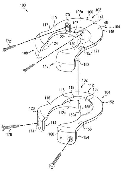
Referring now to Figures 19, 20, and 21, in this embodiment, an artificial
intervertebral joint 100 may include two arthroplasty halves 102, 104 which
may be
inserted between the vertebrae 7, 9. The arthroplasty half 102 may be an
articulating joint
replacement assembly and may include a rostral anterior component 106, a
rostral
posterior joint component 108, and a rostral bridge 110 extending between the
anterior
component 106 and the posterior component 108. The rostral anterior component
106
may further include an interlocking wall 107. The arthroplasty half 102 may
further
include a caudal anterior joint component 112, a caudal posterior joint
component 114,
and a caudal bridge 116 extending between the anterior component 112 and the
posterior
component 114. The caudal anterior component 112 may further include an
interlocking
wall 115. The rostral anterior joint component 106 may include a bone
contacting surface
106a, and the caudal anterior joint component 112 may include a bone
contacting surface
112a.
The terms "rostral" and "caudal" are used in some embodiments to describe the
position of components of the embodiments. While rostral is typically used in
the art to
describe positions toward the head and caudal is used to describe positions
toward the tail
or foot, as used herein, rostral and caudal are used simply as modifiers for
the relative
locations of components of the illustrated embodiments. For example, rostral
components
may be on one side of an illustrated joint, and caudal may be on another side
of the joint.
Components labeled as rostral or caudal to describe an illustrated embodiment
are not
CA 02552522 2006-06-30
WO 2005/067824 PCT/US2005/000648
14
intended to limit the orientation of a device or application of a method
relative to a
patient's anatomy, or to limit the scope of claims to any device or method.
In this embodiment, the rostral bridge 110 may include a jog 117 to create an
exit
portal and an artificial foramen for the exiting nerve root. Either of the
bridges 110, 116,
but particularly the caudal bridge 116, may be a "super" or artificial pedicle
which may
supplement or replace a natural pedicle. Also in this embodiment, the caudal
anterior joint
component 112 may include a caudal articulating surface such as a curved
protrusion 118,
and the caudal posterior joint component 114 may include a posterior
articulating portion
120. The rostral anterior joint component 106 may include a rostral
articulating surface
such as an anterior socket 122 configured to receive the curved protrusion
118. A radius
of curvature for the curved protrusion 118 may closely match the radius of
curvature for
the anterior socket 122 to create a highly constrained ball and socket type
engagement. In
an alternative embodiment, by increasing the radius of curvature for the
socket relative to
the radius of the curved protrusion, the curved protrusion may be permitted to
translate
within the socket.
The rostral posterior joint component 108 may include a posterior socket 124
configured to engage the posterior articulating portion 120. A radius of
curvature for the
posterior articulating portion 120 may be smaller than a radius of curvature
for the
posterior socket 124, thereby permitting motion and limiting binding between
the posterior
joint components 108, 114. The radii of curvature for the posterior socket 124
and the
posterior articulating portion 120 may emanate from a common center of
rotation for the
arthroplasty half 102. In this embodiment, the radius of curvature for the
posterior socket
124 is relatively large, and the resulting joint is loosely constrained. In an
alternative
embodiment, a tight radius of curvature for the posterior protrusion of the
caudal posterior
component matched with a rostral posterior component having a tight radius of
curvature
may create a tightly constrained posterior joint.
The arthroplasty half 104 may be an articulating joint replacement assembly
and
may include a rostral anterior joint component 146, a rostral posterior joint
component
148, and a rostral bridge 150 extending between the anterior component 146 and
the
posterior component 148. The rostral anterior component 146 may further
include an
interlocking wall 147. The arthroplasty half 104 may further include a caudal
anterior
CA 02552522 2006-06-30
WO 2005/067824 PCT/US2005/000648
joint component 152, a caudal posterior joint component 154, and a caudal
bridge 156
extending between the anterior component 152 and the posterior component 154.
The
caudal anterior component 152 may further include an interlocking wall 155.
The rostral
anterior joint component 146 may include a bone contacting surface 146a and
the caudal
anterior joint component 152 may include a bone contacting surface 152a.
In this embodiment, the rostral bridge 150 may include a jog 157 to create an
exit
portal and an artificial foramen for the exiting nerve root. Also in this
embodiment, the
caudal anterior joint component 152 may include a caudal articulating surface
such as a
curved protrusion 158. The rostral anterior joint component 146 may include a
rostral
10 articulating surface such as an anterior socket 171 configured to receive
the curved
protrusion 158. A radius of curvature for the curved protrusion 158 may
closely match
the radius of curvature for the anterior socket 171 to create a highly
constrained ball and
socket type engagement. In an alternative embodiment, by increasing the radius
of
curvature for the socket relative to the radius of the curved protrusion, the
curved
15 protrusion may be permitted to translate within the socket.
Also in this embodiment, the caudal posterior joint component 154 may include
a
posterior articulating portion 160. The rostral posterior joint component 148
may include
a posterior socket 162 configured to engage the posterior articulating portion
160. A
radius of curvature for the posterior articulating portion 160 may be smaller
than a radius
of curvature for the posterior socket 162, thereby permitting motion and
limiting binding
between the posterior joint components 148, 154. The radii of curvature for
the posterior
socket 162 and the posterior articulating portion 160 may emanate from a
common center
of rotation for the arthroplasty half 104. In this embodiment, the radius of
curvature for
the posterior socket 162 is relatively large, and the resulting joint is
loosely constrained.
In an alternative embodiment, a tight radius of curvature for the posterior
protrusion of the
caudal posterior component matched with a rostral posterior component having a
tight
radius of curvature may create a tightly constrained posterior joint.
The size and shape of the anterior components 106, 112, 146, 152 and the
bridge
components 110, 116, 150, 156 may be limited by the constraints of a posterior
or
transforaminal surgical approach. For example, the anterior components 106,
112, 146,
152 may be configured to cover a maximum vertebral endplate area to dissipate
loads and
CA 02552522 2006-06-30
WO 2005/067824 PCT/US2005/000648
16
reduce subsidence while still fitting through the posterior surgical exposure,
Kambin's
triangle, and other neural elements. The width of the bridge components 110,
116, 150,
156 are also minimized to pass through Kambin's triangle and to co-exist with
the neural
elements.
The arthroplasty halves 102, 104 may further includes features for securing to
the
vertebrae 7, 9. It is understood, however, that in an alternative embodiment,
the fixation
features may be eliminated. The arthroplasty half 104 may include fixation
features
substantially similar to arthroplasty half 102 and therefore will not be
described in detail.
The arthroplasty half 102 may include a connection component 170 extending
rostrally
from the rostral anterior joint component 106. The connection component 170 in
this
embodiment includes an aperture adapted to receive a bone fastener such as a
screw 172.
The orientation of the connection component 170 permits interbody fixation of
the screw
172 to the cylindrical vertebral body 7a.
Arthroplasty half 102 may further include a connection component 174 attached
to or integrally formed with the caudal posterior joint component 114. The
connection
component 174 in this embodiment includes an aperture adapted to receive a
bone fastener
such as a screw 176. The orientation of the connection component 174 permits
the screw
176 to become inserted extrapedicularly such that the screw travels a path
angled or
skewed away from a central axis defined through a pedicle. Extrapedicular
fixation may
be any fixation into the pedicle that does not follow a path down a central
axis defined
generally posterior-anterior through the pedicle. In this embodiment, the
screw passes
through a lateral wall of the pedicle and may achieve strong cortical
fixation. In all
embodiments, the screws may be recessed so as not to interfere with
articulations, soft
tissues, and neural structures.
In an alternative embodiment, for example as shown in Figure 14, a connection
component extending from the posterior component 114 may be oriented to permit
the
screw to become inserted intrapedicularly such that the screw travels a path
generally
along the central axis through the pedicle. In still another alternative
embodiment, the
posterior connection component may connect to the generally cylindrical body
portion 9a.
It is understood that in other alternative embodiments, the connection
components may
extend at a variety of angles, in a variety of directions from the various
components of the
CA 02552522 2006-06-30
WO 2005/067824 PCT/US2005/000648
17
arthroplasty half. For example, a connection component may extend from the
rostral
bridge rather than the rostral anterior joint component.
As shown in Figures 19, 20, and 21, the rostral components 106, 108, 110 of
the
articulating joint replacement assembly 102 are integrally formed with rigid
connections
between the components. It is understood that in a modular alternative
embodiment, these
components may be removably coupled to one another. For example, the rostral
anterior
joint component may be installed separate from the bridge. After the anterior
component
is in place, the bridge may be attached to the anterior component by any
fastening
mechanism known in the art, for example a threaded connection, a bolted
connection, or a
latched connection. A modular rostral posterior component may then be attached
by a
similar fastening mechanism to the bridge to complete the rostral portion of
the
arthroplasty half. Likewise, the caudal components may be modular.
The arthroplasty halves 102, 104 may be formed of any suitable biocompatible
material including metals such as cobalt-chromium alloys, titanium alloys,
nickel titanium
alloys, and/or stainless steel alloys. Ceramic materials such as aluminum
oxide or
alumnia, zirconium oxide or zirconia, compact of particulate diamond, and/or
pyrolytic
carbon may also be suitable. Polymer materials may also be used, including any
member
of the polyaryletherketone (PAEK) family such as polyetheretherketone (PEEK),
carbon-
reinforced PEEK, or polyetherketoneketone (PEKK); polysulfone; polyetherimide;
polyimide; ultra-high molecular weight polyethylene (UHMWPE); and/or cross-
linked
UHMWPE. The various components comprising the arthroplasty halves 102, 104 may
be
formed of different materials thus permitting metal on metal, metal on
ceramic, metal on
polymer, ceramic on ceramic, ceramic on polymer, or polymer on polymer
constructions.
Bone contacting surfaces of the arthroplasty halves 102, 104 may include
features or
coatings which enhance the fixation of the implanted prosthesis. For example,
the
surfaces may be roughened such as by chemical etching, bead-blasting, sanding,
grinding,
serrating, and/or diamond-cutting. All or a portion of the bone contacting
surfaces of the
arthroplasty halves 102, 104 may also be coated with a biocompatible and
osteoconductive
material such as hydroxyapatite (HA), tricalcium phosphate (TCP), and/or
calcium
carbonate to promote bone in growth and fixation. Alternatively,
osteoinductive coatings,
such as proteins from transforming growth factor (TGF) beta superfamily, or
bone-
CA 02552522 2006-06-30
WO 2005/067824 PCT/US2005/000648
18
morphogenic proteins, such as BMP2 or BMP7, may be used. Other suitable
features may
include spikes, ridges, and/or other surface textures.
The artificial intervertebral joint 100 may be installed between the vertebrae
7, 9
as will be described below using a bilateral delivery. Generally, the
artificial
intervertebral joint 100 may be implanted into a body using a posterior
transforaminal
approach similar to the known TLIF or PLIF procedures. PLIF approaches are
generally
more medial and rely on more retraction of the traversing root and dura to
access the
vertebral interspace. The space between these structures is known as Kambin's
triangle.
TLIF approaches are typically more oblique, requiring less retraction of the
exiting root,
and less epidural bleeding with less retraction of the traversing structures.
It is also
possible to access the interspace using a far lateral approach, above the
position of the
exiting nerve root and outside of Kambin's triangle. In some instances it is
possible to
access the interspace via the far lateral without resecting the facets.
Furthermore, a direct
lateral approach through the psoas is known. This approach avoids the
posterior neural
elements completely. Embodiments of the current invention are anticipate that
could
utilize any of these common approaches.
According to at least one of these approaches, an incision, such as a midline
incision, may be made in the patient's back and some or all of the affected
disc and
surrounding tissue may be removed via the foramina. The superior endplate
surface of the
vertebra 9 may be milled, rasped, or otherwise resected to match the profile
of the caudal
anterior bone contacting surface 112a, to normalize stress distributions on
the superior
endplate surface of the vertebra 9, and/or to provide initial fixation prior
to bone ingrowth.
The preparation of the endplate of vertebra 9 may result in a flattened
surface or in surface
contours such as 'pockets, grooves, or other contours that may match
corresponding
features on the bone contacting surface 112a. The inferior endplate of the
vertebra 7 may
be similarly prepared to receive the rostral anterior joint component 106 to
the extent
allowed by the exiting nerve root and the dorsal root ganglia. Depending on
whether any
of the facet joints are being replaced, the natural facet joints of vertebrae
7, 9 may be
trimmed to make room for the posterior components 108, 114.
The articulating joint replacement assembly 102 of the artificial
intervertebral
joint 100 may then be inserted piecewise through, for example, the left
transforaminal
CA 02552522 2006-06-30
WO 2005/067824 PCT/US2005/000648
19
exposure. That is, the pieces of the articulating joint replacement assembly
102 including
the rostral and caudal anterior joint components 106, 112 respectively are fit
through the
foramina and are placed in the appropriate intervertebral disc space between
the generally
cylindrical bodies 7a, 9a. The anterior joint components 106, 112 may be
delivered along
a curved path similar to that used in a "kidney bean" TLIF graft. Within the
intervertebral
disc space, the anterior joint components 106, 112 may be positioned such that
the anterior
socket 122 is engaged with the curved protrusion 118 to form one lateral half
of a single,
unitized ball and socket style joint. The joint formed by the anterior socket
122 and the
curved protrusion 118 may abut a central anterior-posterior axis 127 through
the
intervertebral disc space. As described, the anterior articulation provided by
the anterior
socket 122 engaged with the curved protrusion 118 may be completed with
unilateral
delivery. If the articulating joint replacement assembly 104 cannot be
inserted, the
articulating joint replacement assembly 102 may function on its own. During
insertion,
the pieces of the articulating joint replacement assembly 102 may be
completely separated
or two or more of them may be tied or packaged together prior to insertion
through the
foramina by cloth or other materials known in the art. In cases where at least
a portion of
the outer annulus of the natural disc can be retained, the caudal anterior
joint components
may be inserted such that they abut a corresponding portion of the annulus.
The bridges 110, 116 may extend posteriorly from the anterior joint components
106, 112, respectively and posteriorly from the intervertebral disc space. The
posterior
components 108, 114 may be positioned posteriorly of the intervertebral disc
space with
the posterior socket 124 engaged with the posterior articulating portion 120.
These
posterior components 108, 114 may replace or supplement the function of the
natural facet
joints. Similar positioning may be completed for the components of the
arthroplasty half
104. In addition to joining the anterior and posterior components, the bridges
110, 116,
150, 156 may serve to prevent subsidence. By crossing onto either the pedicle
(for caudal
bridges 116, 156) or the posterior wall of the apophyseal ring (for rostral
bridges 110, 150)
greater surface area is created and bone subsidence may be reduced.
The articulating joint replacement assembly 104 of the artificial
intervertebral
joint 100 may then be inserted piecewise through a contralateral exposure, for
example, a
right transforaminal exposure. That is, the pieces of the articulating joint
replacement
CA 02552522 2006-06-30
WO 2005/067824 PCT/US2005/000648
assembly 104 including the rostral and caudal anterior joint components 146,
152
respectively fit through the contralateral foramina and are placed in the
appropriate
intervertebral disc space between the generally cylindrical bodies 7a, 9a. The
anterior
joint components 146, 152 may also be delivered along a curved path similar to
that used
in a "kidney bean" TLIF graft or any other path that accommodates the shape of
the
components. The pieces of the articulating joint replacement assembly 104 may
be
completely separated or two or more of them may be tied or packaged together
prior to
insertion through the foramina by cloth or other materials known in the art.
Within the intervertebral disc space, the anterior joint components 146, 152
may
10 be positioned such that the anterior socket 171 is engaged with the curved
protrusion 158
to form one lateral half of a single, unitized ball and socket style joint.
The joint formed
by the anterior socket 171 and the curved protrusion 158 may abut the central
anterior-
posterior axis 127 through the intervertebral disc space.
Also within the intervertebral disc space, the anterior joint components 146,
152
15 may be connected to the anterior joint components 106, 112, respectively.
In this
embodiment, the interlocking wall 115 of the caudal anterior joint component
112 may be
placed into engagement with the interlocking wall 155 of the caudal anterior
joint
component 152. Curved protrusion 118 may thus become connected to curved
protrusion
158, which in this embodiment may result in the formation of single kidney-
shaped
20 protrusion centered about the axis 127. The rostral anterior joint
component 106 may be
similarly positioned with respect to the rostral anterior joint component 146,
with the
interlocking wall 122 engaged with the interlocking wall 147. Anterior socket
122 may
thus become connected to anterior socket 171, which in this embodiment may
result in the
formation of a single kidney-shaped recess centered about the axis 127. All
together, the
joint formed by the anterior socket 122 with the curved protrusion 118 and the
joint
formed by the anterior socket 171 with the curved protrusion 158 form a single
unitized
intervertebral joint centered about the axis 127. This single unitized
intervertebral joint
may allow for a common center of rotation for the various components of the
artificial
joint 100, including the posterior joints. The various articulating surfaces
of the joint 100
may be formed by concentric spheres, such that motions in both the anterior
joint and the
posterior joints occur about a common point.
CA 02552522 2006-06-30
WO 2005/067824 PCT/US2005/000648
21
In an alternative embodiment, only the rostral joint components may be
connected. In another alternative embodiment, only the caudal joint components
may be
connected. In another alternative, the contralateral exposure may be abandoned
if
problems occur during the surgery. Thus, the arthroplasty may be completed
with the
unilateral delivery of only the articulating joint replacement assembly 102.
The bridges 150, 156 may extend posteriorly from the anterior joint components
146, 152 and posteriorly from the intervertebral disc space. The posterior
components
148, 154 may be positioned posteriorly of the intervertebral disc space with
the posterior
socket 162 engaged with the posterior articulating portion 160. These
posterior
components 148, 154 may replace or supplement the function of the natural
facet joints.
After installation, the articulating joint replacement assembly 102 and the
articulating joint
replacement assembly 104 may be secured to vertebrae 7, 9. The screw 172 may
be
inserted through the connection component 170 and into the generally
cylindrical body 7a.
The screw 176 may be inserted through the connection component 174 and may be
affixed
extrapedicularly to the vertebra 9, for example, the screw 176 may pass
through a lateral
wall of the pedicle to achieve strong cortical fixation. Corresponding
fasteners may be
used to secure the articulating joint replacement assembly 104. It is
understood that the
screws may be implanted either after the entire arthroplasty half has been
implanted or
after each of the rostral and caudal component has been implanted.
As installed, the unitized anterior ball and socket type joint created by the
anterior
joint components 106, 112, 146, 152 may be relatively stable and self
centering. Both the
anterior and the posterior joints allow the arthroplasty halves 102, 104 to
resist shear
forces, particularly anterior-posterior forces. Movement of the rostral
anterior joint
component 106 relative to the caudal anterior joint component 112 may be
limited by the
displacement of the posterior articulating portion 120 within the posterior
socket 124. For
example, lateral translation of the rostral anterior joint component 106
relative to the
caudal anterior joint component 112 may be limited by the posterior joint.
Similar
constraints may arise in the arthroplasty half 104. Rotational motion about a
longitudinal
axis defined by the cylindrical bodies 7a, 9a may be limited both by the
constraint in the
posterior joints and by the combined constraint provided by the two
arthroplasty halves
CA 02552522 2006-06-30
WO 2005/067824 PCT/US2005/000648
22
102, 104. Further, the posterior joints may restrict any true lateral bending
degree of
freedom.
Pure freedom of motion may be limited to flexion-extension motion about an
axis
defined through the anterior joints of the articulating joint replacement
assemblies 102,
104. However, under certain conditions, the joint 100 may overcome these
design
restrictions to permit limited lateral, rotational, and coupled movements. For
example, the
anterior joint components 106, 112 may become disconnected from each other and
experience limited "lift-off," thereby permitting additional degrees of
freedom and
coupled motions beyond strict flexion-extension motion. The self centering
nature of the
anterior joint may encourage reconnection and alignment after lift-off occurs.
The limited
disconnection of the anterior joint components 106, 112 may be accommodated by
the
degree of constraint in the posterior joint. For example, relatively loose
constraint in the
posterior joint permits greater amounts of lift-off. Some degree of constraint
in the
posterior joint may be useful, however, to encourage reconnection and
alignment of the
anterior joint.
In general, a simple, anteriorly located ball and socket joint which is
tightly
constrained with each component having the same or similar radii of curvature
may allow
flexion-extension, lateral bending, and torsion motions while resisting shear
forces and
limiting translation. By adding an additional highly constrained ball and
socket joint to
the posterior components, an additional degree of freedom may be limited, such
as torsion.
Additional joints may further limit degrees of freedom of motion. If the
anterior or
posterior joints are permitted to disconnect or disarticulate additional
degrees of freedom
may be permitted as described above. Changing the shape of or clearance
between the
ball and socket components will also permit additional degrees of motion.
Referring now to Figures 22 and 23, in this embodiment, an artificial
intervertebral
joint may be substantially similar to artificial intervertebral joint 100
except for the
differences described below. In this embodiment, a caudal anterior joint
component 202
may include an interlocking wall 204, and a caudal anterior joint component
206 may
include an interlocking wall 208. The interlocking wall 204 may include a
connection
mechanism 210, and the interlocking wall 206 may include a connection
mechanism 212.
In this embodiment, the connection mechanism 210 is a female component of a
dove-tail
CA 02552522 2006-06-30
WO 2005/067824 PCT/US2005/000648
23
connection, and the connection mechanism 212 is a male component of a dove-
tail
connection. In another embodiment, as shown in Figure 24, a lap joint locking
mechanism
may interlock the anterior joint components. In this embodiment, a female
component 214
of a lap joint locking mechanism may interlock with a male component 216 of
the lap joint
locking mechanism. In another embodiment, as shown in Figure 25, a connecting
mechanism 218 may include a curved, interlocking wall 220 and a curved
interlocking
wall 222. Similar connections may be provided for rostral anterior components.
In
another embodiment, as shown in Figure 26, a semi-cylindrical locking
mechanism may
interlock the anterior joint components. In this embodiment, a female
component 250 of
the semi-cylindrical locking mechanism may interlock with a male component 252
of the
semi-cylindrical locking mechanism. In another embodiment, as shown in Figure
27, a
tapered cylindrical locking mechanism may interlock the anterior joint
components. In
this embodiment, a male component 254 of the tapered cylindrical locking
mechanism
may have a diameter 256 at a distal end and a diameter 258 at a proximal end,
wherein the
proximal diameter 258 is larger than the distal diameter 256 and the component
254 tapers
from the proximal to the distal end. The.described connection mechanisms are
merely
examples, and any other type of mechanical or adhesive connecting mechanisms
known in
the art may be used as the connecting mechanism.
In an alternative embodiment, a caudal posterior joint component may include a
connection component such as a round aperture. A rostral posterior joint
component may
include a connection component, such as an elongated aperture or slot. A bone
fastener,
such as a bone screw with a bushing, may be inserted through the elongated
aperture and
the round aperture and into the vertebra. The fastener may be allowed to
translate within
the elongated aperture. Accordingly, the anterior articulating joint
replacement
components may be permitted to articulate in a limited flexion-extension
motion as the
fastener translates within the elongated aperture.
Referring now to Figure 28, in this embodiment, an artificial intervertebral
joint
260 may include arthroplasty halves 262, 264. The arthroplasty half 262 may
include a
rostal anterior component 266 and a caudal anterior component 268. The
arthroplasty half
264 may include a rostral anterior component 270 and a caudal anterior
component 272.
The joint 260 may be substantially similar to the joint 100 except that the
rostal
CA 02552522 2006-06-30
WO 2005/067824 PCT/US2005/000648
24
components 266, 270 may be unconnected. Likewise the caudal components 268,
272
may be unconnected and spaced slightly apart. Despite the gap between the
halves 262,
264, the caudal anterior components 268, 272 may have a common center of
curvature
such that the caudal components behave as a unitized bearing.
Referring now to Figure 29, in this embodiment, an artificial intervertebral
joint
280 may be substantially similar to the joint 260 except that rostral
components 282, 284
may include retaining features 286, 288, respectively. The retaining features
286, 288
may prevent lateral disartieulation of the caudal components.
In an alternative embodiment, any of the artificial intervertebral joints
described
above may further include a rostral keel extending from the rostral anterior
component
and/or a caudal keel extending from the caudal anterior joint component and
along the
caudal bridge. The rostral keel may engage the inferior endplate of the
vertebral body 7a,
and the caudal keel may engage the superior endplate of the vertebral body 9a
and a
superior face of a pedicle of vertebra 9. It is understood that the inferior
endplate of the
body 7a may be milled or otherwise prepared to receive the rostral keel.
Likewise, the
superior endplate of the body 9a and the pedicle of vertebra 9 may be milled,
chiseled, or
otherwise prepared to create a channel for receiving the caudal keel. The
keels may help
to connect to the bone and limit movement of the arthroplasty half to the
desired degrees
to freedom. The keels may have an angled or semi-cylindrical cross section. It
is
understood that more than one keel may be used on any given component.
Although only a few exemplary embodiments have been described in detail above,
those skilled in the art will readily appreciate that many modifications are
possible in the
exemplary embodiments without materially departing from the novel teachings
and
advantages of this disclosure. Accordingly, all such modifications and
alternative are
intended to be included within the scope of the invention as defined in the
following
claims. Those skilled in the art should also realize that such modifications
and equivalent
constructions or methods do not depart from the spirit and scope of the
present disclosure,
and that they may make various changes, substitutions, and alterations herein
without
departing from the spirit and scope of the present disclosure. It is
understood that all
spatial references, such as "horizontal," "vertical," "top," "upper," "lower,"
"bottom,"
"left," and "right," are for illustrative purposes only and can be varied
within the scope of
CA 02552522 2006-06-30
WO 2005/067824 PCT/US2005/000648
the disclosure. In the claims, means-plus-function clauses are intended to
cover the
structures described herein as performing the recited function and not only
structural
equivalents, but also equivalent structures.