Language selection

Search

Patent 2552762 Summary

Third-party information liability

Some of the information on this Web page has been provided by external sources. The Government of Canada is not responsible for the accuracy, reliability or currency of the information supplied by external sources. Users wishing to rely upon this information should consult directly with the source of the information. Content provided by external sources is not subject to official languages, privacy and accessibility requirements.

Claims and Abstract availability

Any discrepancies in the text and image of the Claims and Abstract are due to differing posting times. Text of the Claims and Abstract are posted:

  • At the time the application is open to public inspection;
  • At the time of issue of the patent (grant).
(12) Patent Application: (11) CA 2552762
(54) English Title: REFINING ELEMENT
(54) French Title: ELEMENT DE RAFFINAGE
Status: Deemed Abandoned and Beyond the Period of Reinstatement - Pending Response to Notice of Disregarded Communication
Bibliographic Data
(51) International Patent Classification (IPC):
  • B02C 07/12 (2006.01)
  • D21D 01/30 (2006.01)
(72) Inventors :
  • VIRVING, NILS (Sweden)
  • PUROLAINEN, PERTTI (Sweden)
  • HOLMSTEN, LARS (Sweden)
(73) Owners :
  • METSO PAPER, INC.
(71) Applicants :
  • METSO PAPER, INC. (Finland)
(74) Agent: SMART & BIGGAR LP
(74) Associate agent:
(45) Issued:
(86) PCT Filing Date: 2005-01-17
(87) Open to Public Inspection: 2005-08-04
Availability of licence: N/A
Dedicated to the Public: N/A
(25) Language of filing: English

Patent Cooperation Treaty (PCT): Yes
(86) PCT Filing Number: PCT/SE2005/000035
(87) International Publication Number: SE2005000035
(85) National Entry: 2006-07-06

(30) Application Priority Data:
Application No. Country/Territory Date
0400121-0 (Sweden) 2004-01-21

Abstracts

English Abstract


A refining element intended for refiners of disc-type for working fibrous
material, where the refining element (10) is provided with a pattern of bars
(13, 14) and intermediate grooves, and the refining element (10) is divided
into an inner in-feed portion (11) with coarse bars (13) and an outer portion
(12) with fine bars (14). The transition (15) between the inner portion and
outer portion (11 and 12, respectively) extends arc-shaped over the refining
element at varying distance from the inner edge (16) of the refining element.


French Abstract

La présente invention concerne un élément de raffinage destiné à des raffineurs du type à disque utilisés pour travailler les matières fibreuses. L'élément de raffinage (10) est prévu avec une configuration de barres (13, 14) et de rainures intermédiaires, ledit élément de raffinage (10) étant divisé en une partie intérieure d'entrée (11) dotée de grosses barres (13) et d'une partie extérieure (12) dotée de fines barres (14). La transition (15) entre la partie intérieure et la partie extérieure (11 et 12) s'étend en forme d'arc au-dessus de l'élément de raffinage à une distance variable du bord interne (16) de l'élément de raffinage.

Claims

Note: Claims are shown in the official language in which they were submitted.

Claims
1. A refining element intended for refiners of disc-type for working fibrous
material, where the refining element (10) is provided with a pattern of bars
(13, 14) and
intermediate grooves, and the refining element (10) is divided into an inner
in-feed
portion (11) with coarse bars (13) and an outer portion (12) with fine bars
(14),
characterized in that the transition (15) between the inner and outer portion
(11 and,
respectively, 12) extends arc-shaped over the refining element at varying
distance from
the inner edge (16) of the refining element.
2. A refining element as defined in claim 1, characterized in that the
distance of the transition (15) from the inner edge (16) increases
continuously from one
lateral edge (17) of the refining element to the other lateral edge (18).
4

Description

Note: Descriptions are shown in the official language in which they were submitted.


CA 02552762 2006-07-06
WO 2005/070550 PCT/SE2005/000035
Refining element
This invention relates to refiners of disc-type with refining discs rotating
opposedly
relative to one another. The refining discs are provided with refining
elements, which
between themselves form a refining gap with a refining zone for the working of
fibrous
material. The fibrous material preferably is lignocellulosic fibrous material,
and the
refirier is used for the manufacture of, for example, reject pulp, recycled
fiber pulp and
mechanical pulps, such as board pulp, thermomechanical pulp (TMP) and chemi-
thermomechanical pulp (GTMP) and for the low concentration refining of
chemical
pulps.
The invention relates, more definitely, to a refining element to be used in a
refiner of
the kind described above.
A refining element is formed with a pattern of bars and intermediate grooves.
The bars
and grooves are formed in different ways, depending on which fibrous material
is
worked and which working degree, and thus in the case of lignocellulosic
material,
which pulp quality is desired. The bars, for example, can be continuous or
discontinuous and be arranged in different patterns. The working of the
fibrous material
is carried out substantially by the bars of the refining elements. The
refining gap is
formed so that the fibrous material, seen in radial direction, shall pass from
the inside
outward. Farthest inwardly in the refining gap, in an inner portion, the in-
feeding zone,
the refining elements normally are formed with wide bars (coarse pattern) for
bringing
about a first disinfiegration of the material and for advancing the material
outward in the
refining gap. A certain defibering, i.e. a separation of the fibers of the
material, also
takes place in the inner portion of the refining gap where the distance
between the
refining surFaces is the greatest. The refining gap decreases thereafter
outward, i.e. the
distance between the opposed refining surfaces decreases and transforms to a
refining
zone, at the same time as the bars become thinner (finer pattern), in order to
achieve a
desired working or refining of the fibrous material. The bars in the outer
portion are
placed at a greater density, which implies more bar edges for effecting the
main
working of the material. The outer portion can comprise more zones, in which
case the
pattern usually is made tighter from one zone to the other, radially outward.

CA 02552762 2006-07-06
WO 2005/070550 PCT/SE2005/000035
in the transition from the inner portion with the coarse pattern to the outer
portion with
the finer pattern, the material is slowed down. This implies compression of
the material
and increased load on the bars of the refining element in this position. As a
result
thereof the bars of the refining element in the transition between the inner
and outer
portion of the refining element are subjected to increasing wear.
The present invention offers a solution of the aforesaid problem. According to
the
invention, the transition between the inner and outer portion of the refining
element is
formed with arc-shaped varying radial distance from the inner edge of the
refining
element. Thereby the transition of the material from the in-feeding zone to
the refining
zone is distributed over a greater area of the refining element, and the
problem of wear
is reduced substantially.
The characterizing features of the invention are defined in the claims.
The invention is described in greater detail in the following with reference
to the
accompanying Figures illustrating an embodiment of the invention.
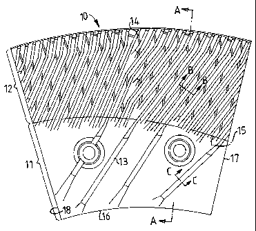
Fig. 1 shows the front side of a refining element with a pattern of bars and
intermediate
grooves,
Fig. 2 is a cross-section according to A-A in Fig 1,
Fig. 3 is a cross-section (B-B) of the bars in the outer portion of the
refining element,
Fig. 4 is a cross-section (C-C) of the bars in the inner portion of the
refining element.
In Fig. 1 a refining element 10 is shown, which is intended for the refining
of fibrous
material. The refining element 10 is provided with a pattern of bars and
intermediate
grooves and is divided into an inner portion 11 and an outer portion 12. The
inner
portion 11 has a coarse pattern with wide bars 13 while the outer portion has
a fine
pattern with narrow bars 14. The transition between these portions is
designated by 15.
The bars 13 in the inner portion 11 of the refining element are intended to
bring about a
first disintegration of the material and to advance the material outward in
the refining

CA 02552762 2006-07-06
WO 2005/070550 PCT/SE2005/000035
gap. A certain defibering, i.e. separation of the fibers of the material, also
takes place in
this portion of the refining element. The bars 14 in the outer portion 12 of
the refining
element are intended to effect a desired working or refining of the fibrous
material.
The transition 15 between the inner portion 11 and the outer portion 12
extends arc-
shaped with varying radial distance from the inner edge 16 of the refining
element. The
refining element suitably is formed so that the distance of the transition 15
from the
inner edge 16 increases continuously from one lateral edge 17 of the refining
element
to the other one 18. But also other configurations of the transition can be
imagined. The
radial distance from the inner edge 16 can for example increase and decrease
one or
several times over the refining element. What is essential is that the
transition is not
located on the same radius over the entire refining element.
The bars 13, 14 suitably are angled in relation to the radius of the refining
element, so
that during the working of the material they promote an outward feeding. The
distance
of the transition 15 from the inner edge 16 then shall increase, counted in
the intended
rotation direction of the refining element.
When refining elements according to the invention is used in a refiner, they
are placed
directly in front of each other on opposed refining discs (refining element
holders) for
rotation relative to another. Due to the fact that the transition 15 between
the inner and
outer portions 11 and 12, respectively, of the refining elements varies
radially, the
effect of the material on the refining elements at the transition is
distributed over a
greater area. This implies that the wear is substantially reduced, and the
service life of
the refining elements increases, and at the same time the feeding will be more
uniform
and improved. This results altogether in that the operational safety can be
improved
and the pulp puality be increased.
The invention, of course, is not restricted to the embodiments shown, but can
be varied
within the scope of the claims with reference to the description and Figures.
3

Representative Drawing
A single figure which represents the drawing illustrating the invention.
Administrative Status

2024-08-01:As part of the Next Generation Patents (NGP) transition, the Canadian Patents Database (CPD) now contains a more detailed Event History, which replicates the Event Log of our new back-office solution.

Please note that "Inactive:" events refers to events no longer in use in our new back-office solution.

For a clearer understanding of the status of the application/patent presented on this page, the site Disclaimer , as well as the definitions for Patent , Event History , Maintenance Fee  and Payment History  should be consulted.

Event History

Description Date
Application Not Reinstated by Deadline 2011-01-17
Time Limit for Reversal Expired 2011-01-17
Inactive: Abandon-RFE+Late fee unpaid-Correspondence sent 2010-01-18
Deemed Abandoned - Failure to Respond to Maintenance Fee Notice 2010-01-18
Letter Sent 2006-11-08
Inactive: Single transfer 2006-10-17
Inactive: Courtesy letter - Evidence 2006-09-19
Inactive: Cover page published 2006-09-14
Inactive: Notice - National entry - No RFE 2006-09-11
Application Received - PCT 2006-08-17
National Entry Requirements Determined Compliant 2006-07-06
Application Published (Open to Public Inspection) 2005-08-04

Abandonment History

Abandonment Date Reason Reinstatement Date
2010-01-18

Maintenance Fee

The last payment was received on 2008-12-19

Note : If the full payment has not been received on or before the date indicated, a further fee may be required which may be one of the following

  • the reinstatement fee;
  • the late payment fee; or
  • additional fee to reverse deemed expiry.

Patent fees are adjusted on the 1st of January every year. The amounts above are the current amounts if received by December 31 of the current year.
Please refer to the CIPO Patent Fees web page to see all current fee amounts.

Fee History

Fee Type Anniversary Year Due Date Paid Date
Basic national fee - standard 2006-07-06
MF (application, 2nd anniv.) - standard 02 2007-01-17 2006-07-06
Registration of a document 2006-10-17
MF (application, 3rd anniv.) - standard 03 2008-01-17 2008-01-03
MF (application, 4th anniv.) - standard 04 2009-01-19 2008-12-19
Owners on Record

Note: Records showing the ownership history in alphabetical order.

Current Owners on Record
METSO PAPER, INC.
Past Owners on Record
LARS HOLMSTEN
NILS VIRVING
PERTTI PUROLAINEN
Past Owners that do not appear in the "Owners on Record" listing will appear in other documentation within the application.
Documents

To view selected files, please enter reCAPTCHA code :


To view images, click a link in the Document Description column. To download the documents, select one or more checkboxes in the first column and then click the "Download Selected in PDF format (Zip Archive)" or the "Download Selected as Single PDF" button.

List of published and non-published patent-specific documents on the CPD .

If you have any difficulty accessing content, you can call the Client Service Centre at 1-866-997-1936 or send them an e-mail at CIPO Client Service Centre.


Document
Description 
Date
(yyyy-mm-dd) 
Number of pages   Size of Image (KB) 
Drawings 2006-07-05 1 43
Abstract 2006-07-05 2 93
Claims 2006-07-05 1 20
Description 2006-07-05 3 151
Representative drawing 2006-09-13 1 28
Notice of National Entry 2006-09-10 1 193
Courtesy - Certificate of registration (related document(s)) 2006-11-07 1 106
Reminder - Request for Examination 2009-09-20 1 117
Courtesy - Abandonment Letter (Maintenance Fee) 2010-03-14 1 172
Courtesy - Abandonment Letter (Request for Examination) 2010-04-25 1 164
PCT 2006-07-05 3 118
Correspondence 2006-09-10 1 26