Language selection

Search

Patent 2552764 Summary

Third-party information liability

Some of the information on this Web page has been provided by external sources. The Government of Canada is not responsible for the accuracy, reliability or currency of the information supplied by external sources. Users wishing to rely upon this information should consult directly with the source of the information. Content provided by external sources is not subject to official languages, privacy and accessibility requirements.

Claims and Abstract availability

Any discrepancies in the text and image of the Claims and Abstract are due to differing posting times. Text of the Claims and Abstract are posted:

  • At the time the application is open to public inspection;
  • At the time of issue of the patent (grant).
(12) Patent Application: (11) CA 2552764
(54) English Title: QUICK-COUPLING/MOUNTING SYSTEM FOR ELEVATOR GUIDES
(54) French Title: SYSTEME D'ASSEMBLAGE/DE MONTAGE RAPIDE POUR GUIDES D'ASCENSEUR
Status: Deemed Abandoned and Beyond the Period of Reinstatement - Pending Response to Notice of Disregarded Communication
Bibliographic Data
(51) International Patent Classification (IPC):
  • B66B 07/02 (2006.01)
(72) Inventors :
  • SANZ GAMBOA, JESUS (Spain)
(73) Owners :
  • S.A. DE VERA (SAVERA)
(71) Applicants :
  • S.A. DE VERA (SAVERA) (Spain)
(74) Agent: ROBIC AGENCE PI S.E.C./ROBIC IP AGENCY LP
(74) Associate agent:
(45) Issued:
(86) PCT Filing Date: 2005-01-21
(87) Open to Public Inspection: 2005-08-04
Availability of licence: N/A
Dedicated to the Public: N/A
(25) Language of filing: English

Patent Cooperation Treaty (PCT): Yes
(86) PCT Filing Number: PCT/ES2005/000025
(87) International Publication Number: ES2005000025
(85) National Entry: 2006-07-06

(30) Application Priority Data:
Application No. Country/Territory Date
P-200400162 (Spain) 2004-01-26
P-200400169 (Spain) 2004-01-27
P-200402613 (Spain) 2004-10-29

Abstracts

English Abstract


The invention relates to a quick-coupling/mounting system for elevator guides,
in which each guide (1) comprises a central plate (13) and wings (14) bearing
machined segments (141) which are disposed around pre-defined connecting
points (P). The inventive system comprises connecting plates (2) which are
divided into two plate parts (2a) which can move on clamping means (2b), (21),
(22). According to the invention, the clamping means are mounted to the
aforementioned plate parts (2a) and, when the parts are moved closer together,
the clamping means clamp said parts (2a) laterally against the wings (14). In
addition, each plate part (2a) is equipped with aligning elements (3), (241)
which are centred on, and fitted together with the above-mentioned machined
segments (141) at the connecting points (P) of the wings (14). The invention
can be used for the production of elevator guides.


French Abstract

L'invention concerne un système d'assemblage/de montage rapide pour des guides d'ascenseur. Chaque guide (1) comprend une âme (13) et des ailes (14) qui comportent des parties usinées (141) disposées autour de points d'assemblage (P) prédéfinis. Des plaques d'assemblage (2) structurées en deux parties de plaque (2a) peuvent se déplacer sur des moyens de serrage (2b), (21), (22). Ces moyens de serrage sont montés sur lesdites parties de plaque (2a) et, lorsque celles-ci sont rapprochées l'une de l'autre, lesdits moyens de serrage serrent latéralement lesdites parties de plaque contre les ailes (14). Des éléments d'alignement (3), (241) sont disposés dans chaque partie de plaque (2a), ces éléments étant centrés sur les pièces usinées (141) et montés sur celles-ci au niveau de points d'assemblage (P) des ailes (14). L'invention est mise en application dans la production de guides d'ascenseur.

Claims

Note: Claims are shown in the official language in which they were submitted.

-11-
CLAIMS
1.- Rapid connection/assembly system, for lift guides, where
each guide (1) includes a head-core (13) where a precision finish has
been carried out on its upper surface of reference (11) (OX-axis) and a
precision finish on its side surfaces of reference (12) (OY-axis) and a
flange 814) on each side; characterised because:
a) at least one connection point (P) is determined on each
flange (14) of each guide (1), situated at a predetermined set height
/h) with respect to the upper surface of reference (11) of the head
813) and at a predetermined set distance (a) with respect to the
respective side surface of reference (12) of the head (13);
b) a machine finish (141) open to the outside is placed on
the flanges (14) around each connection point (P);
c) some connection plates (2) are placed, each one of which
extends between the flanges (14) of each side of at least two guides
(1); this connection plate (2) is organised into two plate parts (2a)
which match the flanges (14) of each side and which can be moved in
some tightening means (2b), (21), (22) mounted on these plate parts
(2a), which, when moved closer together, tighten these plate parts
(2a) laterally against the flanges (14);
d) on each plate part (2a) there are alignment elements (3),
(241) which centrally and in a combined way match the machined
parts (141) on the connection points (P) of the flanges), so that when
the plate parts (2a) are tightened against the flanges (14) all the
connection points (P) of the flanges (14) of each side of the guides (1)
remain in a straight line (I).

-12-
2.- Rapid connection/assembly system, for lift guides,
according to previous claim, characterised because:
a) each flange (14) forms some open machined parts (141)
in origin; these machined parts are placed in opposing pairs: one or
several pairs spaced out at any distance (d1) the last of these pairs
being machined at any distance (d2) from the end of the guide (1);
b) the upper surface (11) and the side surfaces (12) of the
head (13) are used as reference to position in origin the open
machined parts (141), whose centres are the connection points (P);
c) a connection plate (2) is placed, organised into two plate
parts (2a) with tightening means (2b) to bring them closer/separate
them to a maximum distance (d3), and which form some alignment
elements (241) in origin, which are distributed into at least two pairs
separated from each other by a distance (d4); these alignment
elements (241) form the retention means which, integrated into the
actual connection plate (2) and dependent upon this, attach is securely
and jointly to the flanges (14) of two guides (1) to be joined;
so that for the rapid connection/assembly, it is sufficient to place the
machined parts (141) opposite each other, (241) of the guides (1) and
compress longitudinal-parts (2a) of this connection plate (2) closer
together.
3.- Rapid connection/assembly system, for lift guides,
according to claim 2, characterised because the alignment elements
(241) are distributed into at least four pairs separated from each other,
two by two by a distance (d5).

-13-
4.- Rapid connection/assembly system, for lift guides,
according to claims 2 and 3, characterised because in the relationship
between distances (d1), (d2), (d4), (d5) the following must be satisfied:
d4 = 2d2 y d5 = d1
5.- Rapid connection/assembly system, for lift guides,
according to previous claims, characterised because each plate part
(2a) is an elongated "U"-shaped profile with asymmetrical flanges, one
of them bent towards the interior, and couples of conformations (20)
opposite each other, to house the tightening means (2b).
6.- Rapid connection/assembly system, for lift guides,
according to claim 5, characterised because these alignment elements
(241), which form the integrated retaining means and dependent on
the base plate (2) are protuberances that are dimensionally combined
with the open machined parts (141) and forming the bend of one of
the asymmetric flanges of these plate parts (2a).
7.- Rapid connection/assembly system, for lift guides,
according to previous claims, characterised because the
aforementioned tightening means (2b) are sets of stud (21) and nut
(22), housed in opposing conformation sets (20) on the plate parts
(2a) so that the maximum separation distance (d3) between plate parts
(2a) is delimited, respectively, by the nut (22) and the head (21b) of
the stud (21).
8.- Rapid connection/assembly system, for lift guides,
according to claim 5, characterised because these conformations (20)
are, in each set, an anti-rotation opening (20a) and an open box (20b).

-14-
9.- Rapid connection/assembly system, for lift guides,
according to claims 1 to 4, characterised because the plate parts (2a)
are solid, with an extension wall on whose end the alignment elements
(241) are placed forming a bend.
10.- Rapid connection/assembly system, for lift guides,
according to claim 9, characterised because these conformations (20)
are through openings.
11.- Rapid connection/assembly system, for lift guides,
according to claim 1, characterised because:
a) each flange (14) forms some machined parts (141) in
origin; these machined parts are placed in opposing pairs: one or
several pairs are separated between each other by any distance (d1)
the last of these pairs being machined at any distance (d2) from the
end of the guide (1);
b) the upper surface (11) and side surfaces (12) of the head
(13) are used as reference to position the open machined parts (141)
in origin, whose centres are the connection points (P);
c) there is a connection plate (2) organised into two plate
parts (2a) with tightening means (2b) bring them closer
together/further apart, to a maximum distance (d3);
d) there are alignment elements (3) pre-mounted on these
plate parts (2a) that can be moved closer;
so that for the rapid connection/assembly it is sufficient to position the
open machined parts (141) of the guides (1) opposite the alignment
elements (3) pre-mounted on the connection plate (2), then

-15-
compressing the plate parts (2a) of this connection plate (2) when
moved closer to.
12.- Rapid connection/assembly system, for lift guides,
according to claim 11, characterised because the plate parts (2a) are
solid and the alignment elements (3) are spigots inserted into these
plate parts (2a) so that they interrupt the continuity of some
longitudinal guides (25) that cover some continuous chamfers (15)
that attach to each other the open machined parts (141) of the guides
(1) to be connected.
13.- Rapid connection/assembly system, for lift guides,
according to claims 1 to 4, characterised because these alignment
elements (241) are die-stamped flanges in the core of these plate
parts (2a).
14.- Rapid connection/assembly system, for lift guides,
according to claim 13, characterised because these die-stamped
flanges (241) are conformed in the core of the plate parts (2a).

Description

Note: Descriptions are shown in the official language in which they were submitted.


CA 02552764 2006-07-06
1
QUICK-COUPLINGIMOUNTING SYSTEM FOR ELEVATOR GUIDES
This invention deals with a rapid assembly connection
system for lift guides.
Lift guides require greater and greater quality and precision
coefficients each day, basically due to the users' comfort
requirements. The connections between these guides must be carried
out in compliance with these quality and precision requirements.
to A guide connection is comprised of three basic elements:
a) the actual guides,
b1 guide connection plate,
c) connecting screws of guides with the connection plate.
All the connection systems known suffer from two
problems:
a) these three basic elements are presented independently in
the assembly
b) the alignment of the guides and the connection plate is
complicated per se and this difficulty is greater if we bear in mind that
2o it has to be carried out in places that are difficult to access and in
complicated positions.

CA 02552764 2006-07-06
-2-
In a traditional guide connection system, all of this results in
the coupling operations of the three basic elements, their alignment
and anchor/fastening, usually taking around 9 minutes.
It is understood perfectly that any improvement in the
simplification of the assembly will represent a great advance in this
technological field and will speed up the actual assembly without
detriment of the quality and precision required.
The applicant has realised that in the known connection
system, the connection plate and the guide flanges are joined
to vertically.
The applicant has solved these problems arranging for:
a) the connection plate to be divided into two plate parts
that already have the connecting means/screws mounted
b) the flanges and the plate parts to be equipped with
Is combined alignment configurations, so that their mutual coupling and
relative alignment is carried out very quickly.
The connection plate and the guide flanges are joined
together / tightened horizontally (laterally).
With the invention system, the coupling/alignment/anchor
2o operations take 20 seconds.
More specifically, the rapid connection/assembly system for
lift guides, where each guide includes a head-core on which a
precision finish has been carried out on its upper reference surface
(OX axis) and a precision finish on its side reference surfaces (0Y axis)
2s and one flange on each side, is characterised because:

CA 02552764 2006-07-06
-3-
a) at least one connection point is determined on each
flange of each guide, situated at a predetermined set height with
respect to the upper reference surface of the head and at a
predetermined set distance with respect to its respective reference
s side surface of the head;
b) a machine finish open to the exterior is placed on the
flanges around each connection point;
c) there are some connection plates, each one of which
extends between the flanges of each side of at least two guides; this
to connection plate is organised into two plate parts that correspond to
the flanges of each side and that can be moved on some torque
means mounted on these plate parts which, when moved closer
together, tighten these plate parts laterally against the flanges;
d) there are alignment elements on each plate part, which
15 correspond centrally and combined with the machine finished at the
connection points of the flanges, so that when the plate parts are
tightened against the flanges, all the connection points of the flanges
of each side of the guides are in a straight line.
In order to understand the subject of this invention better, a
2o preferential form of practical execution is illustrated on the drawings,
subject to incidental changes that take nothing away from its
foundation.
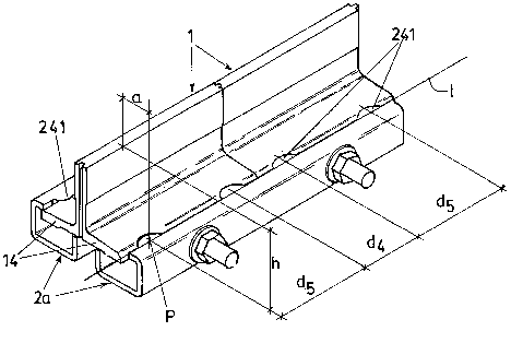
Figures 1 a and 1 b show several general views in frontal
perspective -figure 1 a- and rear perspective -figure 1 b- of a practical
2s execution of the system targeted by the invention.

CA 02552764 2006-07-06
-4-
Figure 2 shows a ground plan corresponding to the previous
figure.
Figure 3a shows a perspective view of a longitudinal-part
(2a) ) (plate part) for the execution of figures 1 and 2 ("U"-shaped
profilel.
Figure 3b shows a perspective view of a longitudinal-part
(2a) (plate part) for the execution of figures 1 and 2, for an alternative
execution (solid part).
Figure 4 shows a partial perspective view of figures 1 and 2
to of one guide (1 ), with a solution of boxes/skating (141 1 (open
machine finish device) machined on the flanges (14).
Figures 5a and 5b show several general front-figure 5a- and
rear -figure 5b- perspective views of another practical execution of
the system targeted by the invention in which the open machined
~s parts ( 141 ) of the guides to be joined together ( 1 ) are open through
boxes and the connection plate (2) is comprised of two longitudinal-
parts (2a) connected to each other with the tightening means, in this
case by two sets of studs (21 )/ nut (22).
Figures 6a and 6b show different general perspective views,
20 one front and one rear of another practical execution of the system
targeted by the invention in which the open machined parts (hidden) of
the guides to be connected (1 ) are spaced open boxes and are
connected together by continuous chamfers (15). These chamfers (15)
are double and the connection plate (2) is comprised of two solid
2s longitudinal-parts (2a) (plate parts) connected together by two sets of
stud (21 ) / (22) (tightening means) and with a longitudinal box (25).

CA 02552764 2006-07-06
-S-
Figure 7 shows a general front perspective view of another
practical execution of the system targeted by the invention in which
the machined parts ( 141 ) of the guides to be connected together ( 1 )
are open boxes and the alignment elements (214) are die-stamped
s flanges integrated into the longitudinal-parts (2a).
Figure 8 is a schematic description of the connection with a
minimum number of connection points (P) between each other, that is,
one connection point (P) for each flange .
Below an example of a non-limitative practical execution of
to this invention is described.
The rapid connection/assembly system for lift guides,
targeted by the invention, is used on guides (1 ), which include a core-
head (13) and a flange (14) on each side.
According to said invention:
1s - The core-head (13) of each guide has a precision finish on
its upper surface (1 1 ) - upper surface of reference according to OX-
axis- and a precision finish on its side surfaces (12)- side surfaces of
reference according to OY-axis-.
- Several connection points (P) are determined on each
2o flange ( 14) of each guide ( 1 ), situated at a predetermined set height
(h) with respect to the upper surface of reference (1 1 ) and at a
predetermined set distance (a) with respect to the respective side
surface of reference (12) (they form straight line I).

CA 02552764 2006-07-06
-6-
- There is a connection plate (2) that extends between the
aforementioned connection points (P) of the flanges (14) of each side
of at least two guides ( 1 ) placed continuously.
- There are some alignment elements (241 ) on the
s connection plate (2), combined with some open machined parts (141 )
at connection points (P) on the flanges (14).
- Each flange (14) forms in origin some machined finishes
( 141 ); these machined devices ( 141 ) are placed in opposing pairs (one
on each flange) on the connection points (P): one pair or several pairs
to separated from each other by a distance (d,) the last of these pairs
being machined at any distance (dz) from the end of the guide (1 ).
- The upper surface (11) and side surfaces (12) of the head
(13) are used as reference to position the machined parts (141 ) in
origin. Their centres coincide with the connection points (P), at a set
15 distance (h) from the upper surface of reference (1 1 ) of the head (13)
according to the OY-axis and at a set distance (a) from the side
surfaces of reference ( 12) of the head ( 13) according to the OX-axis.
All of this leads to a much shorter assembly time than that currently
known and an automatic alignment on the OX and OY-axes by means
20 of the machined parts open to the exterior (141 ) on the flanges (14).
- The connection plate (2) (figures 1 to 4) is organised into
two plate parts (2a) (longitudinal-parts) with tightening means (2b) to
bring them closer together or separate them, which, in origin form
some protuberances (241 ) arranged into opposing pairs: at least two
25 pairs separated from each other by a distance (da). These
protuberances (241 ) form the alignment means integrated into the
actual connection plate (2).

CA 02552764 2006-07-06
_'7_
The open machined parts (141 ) formed on the flanges (14)
of the guides (1 ) to be joined together are boxes that are open to the
exterior -see figure 4-. These open machined parts (141 ) are
separated from each other by a distance (d,) and at a distance (dz)
s from the end of the relative guide (1 ) to be joined.
These distances (d,), (dz) which, in principle, may be any,
condition the distances of the connection plate (2) that are defined
below.
In the execution example shown, the tightening means (2b)
to to bring the longitudinal-parts (2a) closer together or further apart,
they are different cross-parts.
For a first variant of this execution example, -see figure 3a-
each longitudinal-part (2a) is an elongated "U"-shaped profile with
asymmetric flanges, which form conformation pairs (20) in both
15 flanges -an anti-rotation opening (20a) and an open box (20b) that
face each other in pairs- and which forms an end bend on one of
them, with many protuberances (241 ) (alignment elements) opposing
each other in pairs and centred and dimensionally combined with the
boxes/skating (141 ) (open machined parts).
2o For a second variant of this execution example -see figure
3b-, each longitudinal-part (2a) is solid with pairs of openings (20)
along its body, from which a wall extends that forms the
protuberances (2411.
!n the execution example shown pairs of protuberances
z5 (241 ) have been machined in the longitudinal-parts 12a). The two
inner pairs are machined at a distance (da) from each other and the

CA 02552764 2006-07-06
_g_
two outer pairs are machined at a distance (d5) from each other -see
figure 1 a-.
da = 2dz and ds = d, must be satisfied -see figures 1 a and
4-.
s The tightening means (2b) are comprised of a set of stud
(21 )/nut (22), which is inserted into a pair of opposing conformations
1201. The maximum separation amplitude (ds) between longitudinal-
parts (2a) is limited by the head (21 b) of the stud (21 ) and by the
actual nut (22) and varies depending on the width of the guides (1 ) to
to be joined together. Therefore, according to the invention, one same
connection plate (2) can be applied to join pairs of guides 11 ) of
different widths (it is understood that, in each connection, the guides
(1 ) are equal to each other).
The retention takes place by clamping the flanges (14) of
15 the guides (1 ) to be connected between this alignment elements
(protuberances) (241 ) inserting them into the boxes/skating (open
machined parts) (141 ) and applying the nuts (22) of the sets of stud
(21 )/nut(22) that form the tightening means (2b). A rotation
momentum takes place when tightening that makes the guides (1) rest
2o upon the protuberances (214) and in the skatings ( 10) of the
longitudinal-parts (2a).
With the executions of figures 5a, 5b, 6a and 6b, the
alignment elements (3) are pre-mounted on the connection plate (2).
The open machined parts ( 141 ) conformed on the edges of
2s the flanges ( 14) of the guides ( 1 ) to be connected are through open
boxes.

CA 02552764 2006-07-06
-9-
In the execution example, in agreement with figures 6a and
6b, the structure of the connection plate (2) comprises plate parts (2a)
and tightening means (2b) in a similar way and layout to that
described, with the peculiarity that the plate parts (2a) include some
s machined parts (25) that are V-shaped longitudinal guides and the pre-
mounted alignment means (3) are spigots inserted into these
longitudinal-parts (plate parts (2a) so that they interrupt the continuity
of these longitudinal guides (25) at distances (d4), (d5) also similar to
those already described.
lo The openmachined parts(141 ) formed on the flanges
(14)
of the guides (1 be connected are open boxes attached
) to each
to
other by continuous chamfers (15),which occupy at least the
length
of the flanges (14)in contact the connection plate (2).
with These
chamfers (15) may be simple
or double
-as in figures
6a and 6b-
~5 without altering, as a result, the essence of the invention, as it only
require varying in a combined way the geometry of the "V "- shaped
guides (25).
In the execution example - in agreement with figure 7- the
open machined parts (141 ) on the connection points (P) formed at the
2o edges of the flanges (14) of the guides (1) to be joined are through
boxes.
Each longitudinal-part (plate part) (2a) is an elongated U-
shaped profile that forms pairs of openings (20) on its flanges
opposing each other in pairs and in its core many aligned die-stamped
2s flanges (241 ) (alignment elements), also opposing each other in pairs.

CA 02552764 2006-07-06
-10-
Figure 8 shows by way of a diagram the simplest execution,
that is, a connection point (P) for each flange (14) of each guide (1)
aligned on each side forming straight lines (I).

Representative Drawing
A single figure which represents the drawing illustrating the invention.
Administrative Status

2024-08-01:As part of the Next Generation Patents (NGP) transition, the Canadian Patents Database (CPD) now contains a more detailed Event History, which replicates the Event Log of our new back-office solution.

Please note that "Inactive:" events refers to events no longer in use in our new back-office solution.

For a clearer understanding of the status of the application/patent presented on this page, the site Disclaimer , as well as the definitions for Patent , Event History , Maintenance Fee  and Payment History  should be consulted.

Event History

Description Date
Application Not Reinstated by Deadline 2009-01-21
Time Limit for Reversal Expired 2009-01-21
Inactive: IPRP received 2008-02-05
Deemed Abandoned - Failure to Respond to Maintenance Fee Notice 2008-01-21
Inactive: Cover page published 2006-09-14
Letter Sent 2006-09-11
Inactive: Notice - National entry - No RFE 2006-09-11
Application Received - PCT 2006-08-17
National Entry Requirements Determined Compliant 2006-07-06
Application Published (Open to Public Inspection) 2005-08-04

Abandonment History

Abandonment Date Reason Reinstatement Date
2008-01-21

Maintenance Fee

The last payment was received on 2006-12-20

Note : If the full payment has not been received on or before the date indicated, a further fee may be required which may be one of the following

  • the reinstatement fee;
  • the late payment fee; or
  • additional fee to reverse deemed expiry.

Patent fees are adjusted on the 1st of January every year. The amounts above are the current amounts if received by December 31 of the current year.
Please refer to the CIPO Patent Fees web page to see all current fee amounts.

Fee History

Fee Type Anniversary Year Due Date Paid Date
Basic national fee - standard 2006-07-06
Registration of a document 2006-07-06
MF (application, 2nd anniv.) - standard 02 2007-01-22 2006-12-20
Owners on Record

Note: Records showing the ownership history in alphabetical order.

Current Owners on Record
S.A. DE VERA (SAVERA)
Past Owners on Record
JESUS SANZ GAMBOA
Past Owners that do not appear in the "Owners on Record" listing will appear in other documentation within the application.
Documents

To view selected files, please enter reCAPTCHA code :


To view images, click a link in the Document Description column (Temporarily unavailable). To download the documents, select one or more checkboxes in the first column and then click the "Download Selected in PDF format (Zip Archive)" or the "Download Selected as Single PDF" button.

List of published and non-published patent-specific documents on the CPD .

If you have any difficulty accessing content, you can call the Client Service Centre at 1-866-997-1936 or send them an e-mail at CIPO Client Service Centre.

({010=All Documents, 020=As Filed, 030=As Open to Public Inspection, 040=At Issuance, 050=Examination, 060=Incoming Correspondence, 070=Miscellaneous, 080=Outgoing Correspondence, 090=Payment})


Document
Description 
Date
(yyyy-mm-dd) 
Number of pages   Size of Image (KB) 
Description 2006-07-05 10 289
Drawings 2006-07-05 6 163
Abstract 2006-07-05 2 93
Claims 2006-07-05 5 156
Representative drawing 2006-07-05 1 16
Notice of National Entry 2006-09-10 1 193
Courtesy - Certificate of registration (related document(s)) 2006-09-10 1 105
Reminder of maintenance fee due 2006-09-24 1 110
Courtesy - Abandonment Letter (Maintenance Fee) 2008-03-16 1 175
PCT 2006-07-05 3 93
Fees 2006-12-19 1 43
PCT 2006-07-05 4 136