Note: Descriptions are shown in the official language in which they were submitted.
CA 02552819 2006-07-06
VARIABLE COMPRESSION ENGINE
TECHNICAL FIELD
The following invention relates to engines, and more specifically, to
variable compression engines.
BACKGROUND ART
In a traditional piston-in-cylinder internal combustion engine, there are four
"strokes": intake; compression; power (expansion); and exhaust. In the intaKe
stroke, the piston commences motion at a point proximal to the head of the
io cylinder and travels to a point distal to the head of the cylinder,
creating an
expanding void in the cylinder between the piston and the cylinder head which
is
suitably ported to atmosphere to fil( with ambient air during such travel. At
the
end of the intake stroke, fluid communication between the atmosphere and the
cylinder is arrested. In the compression stroke, the piston reverses direction
in
the cylinder, thereby compressing the air contained therein. When the air is
. highly compressed (at the end of the compression stroke) fuel mixed with the
compressed air is ignited, to create combustion. In the power stroke, the
piston
is driven to a point distal to the head of the cylinder by the pressurized
combustion products. In the exhaust stroke, the port to atmosphere is again
opened, and the piston travels to the head of the cylinder, expelling the
combustion products to the atmosphere as exhaust.
A problem common to this type of engine is that after the fuel burns, and
the resulting hot gas drives the piston to the end of the power stroke, the
temperature and pressure of the gas are still far above that of the
surrounding
. atmosphere. This heat and pressure are both manifestations of wasted energy.
A further problem common to this type of engine derives from the fact that
the pistons and connecting rods must reverse direction of motion many times a
minute. The forces required to overcome the inertia involved require
substantial
engineering, and generate vibration and wear, leading to maintenance issues.
3 o A further problem common to this type of engine is the efficiency losses
associated with converting a reciprocating linear motion into rotational
power.
The connecting rod and crank gear reach their maximum angle for torque at
about 75 degrees from top dead centre (~TDC"). Littie useful work is done
before
AMENDED SHEET
J1-03-2005 s ' CA 02552819 2006-o~-os EPO - DG CA0302031
a ~. os, z~~5
75 . .
C or after 135 from TDC, so a considerable amount o~iciency is
f 30 degrees from TD
IOSt.
A yet further problem common to this type of engine is that the high
combustion
temperatures under which this engine operates result in relatively high NOx
emissions.
This problem is exhibited, for example, in German Patent Application DE 25 50
360 A (England), which teaches a MULT1ROTARY ENERGY CONVERSION VALVE. In
this patent, it is taught to remove waste heat from the combustion gases using
a heat
exchanger 6a, to create steam in a boiler 20 using this waste heat, and to
inject this
to steam into the outlet rotors 7, to contribute power. Peak combustion
temperature will be
a function of the initial temperature of the working fluid plus the
temperature rise caused
by the fuei combustion.
In United States Patent No. 6530211 (Holtzapple et al.), issued March 11,
2003,
an engine is disclosed which comprises a compressor for ambient air, a
combuster and
.5 an expander. The combuster receives fuel and burns same with the compressed
air to
produce exhaust gases. The expander receives the exhaust gases and expands
them.
The compressor may be a gerotor compressor or a piston compressor having
variabie-
dead-volume control. The expander may be a gerotor expander or a piston
expander
having variable-dead-volume control. The combuster may be a tubular combuster.
The
2o gases exiting the expander are hot; some of the heat from such gases is
removed by
passage through a heat exchanger, which transfers the heat to the gases
entering the
combuster. The variable dead volume device consists of a piston in a cylinder.
The
position of the cylinder in the piston is set by an actuator, such as an
electric servo
motor. When the piston is moved to provide a small dead volume, the gases can
reach
25 high pressures. In contrast, when a large dead volume is provided, gas
pressures , .
remain low. Regulating the compression ratio in this manner allows the power
output of
the engine to be adjusted. As well, the gerotor configuration of this engine
overcomes in
part, the vibration and wear issues associated with piston-cylinder engines.
However,
the gerotors are difficult to fabricate. Further, the servos add complexity to
the design,
with attendant maintenance issues.
In United States Patent No. 5101782 (Yang), issued April 7, 1992, a rotary
piston
engine is disclosed. This engine includes two segregated compression and
expansion
chambers and one separate combustion chamber. In the compression and expansion
chambers, a pair of screw-shaped rotors are mounted. In operation, the rotors
in the
35 compression chamber compress air. The compressed air is introduced, with
fuel, to the
AMENDED SHEET
CA0302031
01-03-2005 CA 02552819 2006-07-06
-3-
.. combustion chamber, which is then closed, and the contents ignited, such
that the fuel
burns in a constant volume. The high pressure combustion products are then
ported to
the expansion chamber, which causes the rotation of a further pair of screw-
shaped
' S rotors, and the combustion products are cooled and exhausted. A portion of
the heat
removed from the combustion products is the same heat added to the compressed
air.
This engine is indicated by its inventor to be characterized by high
efficiency, high
reliability and quiet operation. However, the need to employ screw-shaped
rotors adds
to cost, and the engine is prone to the production of high NOx emissions,
resultant from
to the high temperatures employed.
DISCLOSURE OF THE INVENTION
It is an object of the present invention to provide an engine which is
relatively
simple to fabricate, which is relatively efficient and reliable in operation
and which
produces relatively low NOx emissions. This object, amongst others, is. met by
the
a.5 present invention, an engine for use with a load.
According to one aspect, the engine comprises a compressor, combuster means,
a positive displacement air motor, a positive displacement gas ~ expander and
power
transfer means.
The compressor is adapted to receive power and, upon receiving power, to:
2o periodically define a chamber; fill the chamber with ambient air; and carry
out a
pressurization process wherein the chamber volume is decreased to produce
pressurized air.
The combuster means is for receiving fuel and combusting same in a combustion
process with the pressurized air to produce primary exhaust products.
The air motor is adapted to be driven by the primary exhaust products to
produce
power and secondary exhaust products. ~ .
The gas expander is for receiving the secondary exhaust products and expanding
same substantially adiabatically to produce tertiary exhaust products and
power.
The power transfer means is for directing power produced by the air motor and
3 o the gas expander in use to drive the compressor and the load.
The combuster means is adapted to receive varying amounts of fuel, thereby to
cause the power transfer means to drive the load with varying amounts of power
in use.
AMENDED SHEET
CA 02552819 2006-07-06
- 4 -
The combuster means is adapted to receive varying amounts of fuel,
a thereby to cause the power transfer means to drive the load with varying
amounts
of power in use.
. The compressor and radiator are adapted to, during the pressurization
s process, release air from the chamber for said combustion in a manner such
that
the maximum pressure in the chamber during the pressurization process and the
pressure of the primary exhaust products driving the air motor is
substantially
constant at steady state conditions, said constant being a function of the
load
being driven by the power. The compression ratio (CR) can be calculated using
to the following equation:
CR = (V1/V2) I (T2IT1 ), where
- V1 represents the volume swept in the primary compression
chamber, and
- V2 represents the volume swept in the primary expansion chamber,
and
- T1 represents the ambient temperature (in °K), and
- T2 represents the temperature of the gases in the primary expansion
o chamber (in °K).
The relative ratio of V1 versus V2 will determine the nominal minimum
compression ratio of the engine. This is dictated'by the geometry of the
engine
and will not vary. On the other hand, the difference between T1 and T2 will be
25 due both to the temperature increase during compression, and due to the
heat
added by the fuel. When the engine is under a light load, less fuel will be
needed, less heat will be generated and less work will be needed to run the
compressor section. This variable compression ratio means that the engine will
only do as much work compressing the incoming air as is required by torque
3 o demand of the engine, that is, the engine will spontaneously adjust its
compression ratio to engine load, thereby to improve operating efficiency.
Another consequence of this arrangement is that the combustion temperature at
partial fuel loads will be lower than that at the maximum condition, so as to
reduce the tendency of the engine to produce NOx emissions.
35 According to another aspect, the engine comprises a rotary compressor, a
radiator, first and second backflow preventers, a pressure tank, a valve, a
tubular
AMENDED SHEET
CA 02552819 2006-07-06
- 5 -
combuster, a positive displacement rotary air motor, a positive displacement
- rotary gas expander and a shaft.
The compressor is adapted to receive power and, upon receiving power,
to: periodically define a chamber; fill the chamber with ambient air; and
carry out
a pressurization process wherein the chamber volume is decreased to produce
pressurized air.
The radiator is coupled. to the compressor to receive the pressurized air
and adapted to cool said pressurized air and to function as a reservoir
therefor.
The first and second backflow preventers are each coupled to the radiator
1o to permit unidirectional flow therefrom.
The pressure tank is coupled to the first backflow preventer to receive
pressurized air from the radiator.
The valve is coupled to the pressure tank to permit the selective release of
pressurized air from the pressure tank.
The combuster is coupled to the valve and to the second backflow
preventer to receive pressurized air from the radiator and pressurized air
selectively released from the pressure tank and adapted to receive fuel and
combust same in a combustion process with the pressurized air so received to
produce primary exhaust products.
2o The air motor is coupled to the combuster so as to be driven by the
primary exhaust products to produce power and secondary exhaust products.,
The gas expander is coupled to the air motor for receiving the secondary
exhaust products and expanding same substantially adiabaticaily to produce
tertiary exhaust products and power.
The shaft is operatively coupled to each of the compressor, the air motor
and the gas expander for directing power produced by the air motor and the gas
expander in use to drive the compressor and the load.
The combuster is adapted to receive varying amounts of fuel, thereby to
cause the power transfer means to drive the load with varying amounts of power
3o in use.
The compressor is adapted to, during the pressurization process, release
air from the chamber for said combustion in a manner such that the maximum
pressure in the chamber during the pressurization process and the pressure of
AMENDED SHEET
CA 02552819 2006-07-06
~ - 6 -
the primary exhaust products driving the air motor is substantially constant
at
steady state conditions, said constant being a function of the load being
driven by
the power.
Two presently preferred embodiments of the present invention will now be
s described with reference to the attached drawings, which are hereinafter
briefly
described.
BRIEF DESCRIPTION OF DRAWINGS
In the attached dravvings, which are provided for illustration only, and are
not meant in any way to limit the scope of the present invention:
to Fig. 1 is a schematic overview of an engine according to the first
preferred
embodiment of the present invention;
Fig.2 is a front view of an engine 'according to the first preferred
embodiment of~the present invention;
Fig. 3 is a cross-section of the engine of Fig. 2 viewed along line 3-3 of
s5 Figure 2;
Fig. 4 is a front cross-sectional view of the engine of Fig. 2, taken in the
location of line 4-4 of Fig. 3;
Fig. 5 is a front cross-sectional view of the engine of Fig. 2, taken in the
location of line 5-5 of Fig. 3;
2 o Fig. 5a is a cross-sectional view along lines 5a-5a of Fig. 5;
Fig. 6 ~ is a front cross-sectional view of the engine of Fig. 2, taken in the
location of line 6-6 of Fig. 3;
Fig. 7 is a front cross-sectional view of the engine of Fig. 2, taken in the
location of line 7-7 of F'ig. 3;
25 Fig. 8 is a front cross-sectional view of the engine of Fig. 2, taken in
the
location of line 8-8 of Fig. 3;
Fig, 9 is a front cross-sectional view of the engine of Fig. 2, taken in the
location of line 9-9 of Fig. 3;
Fig. 10 is a front cross-sectional view of the engine of Fig. 2, taken in the
3 0 location of line 10-10 of Fig. 3;
Fig. 11 a is a side view of a tubular combuster of the engine of Fig. 2;
Fig. 11 b is a front view of the tubular combuster of Fig. 11 a;
AMENDED SHEET
CA 02552819 2006-07-06
_ 7 _
r Fig. 11 c is a side cross-sectional view of the tubular combuster
of Fig. 11a;
Fig. 11 d is a cross section of the tubular combuster of Fig.
11 a;
Fig. 12a is a front view of an assembled piston of the engine
of Fig. 2;
Fig. 12b is a side cross-sectional view of the piston of Fig.
12a along fine
12b-12b of Fig. 12a;
Fig. 12c is a top view of the piston of Fig. 12a;
Fig. 13a is a front view of a piston body of the piston of
Fig. 12;
Fig. 13b is a side cross-sectional view of the piston body
of Fig. 13a, taken
along line 13b-13b of Fig. 13a;
to Fig. 13c . is a top view of the piston body of Fig. 13a;
Fig. 14a is a front view of a lobe face seal of the piston
of Fig. ~ 12a;
Fig. 14b is.a rear view of the lobe face seal of Fig. 14a;
Fig. 14c is a top view of the lobe face seal of Fig. 14a;
Fig. 15a is a side view of a piston side seal of the piston
of Fig. 12a;
15 Fig. 15b is a front view of the piston side seal of Fig. 15a;
Fig. 16a is a front view of a lobe tip seal of the piston of
Fig. 12;
Fig. 16b is a top view of the lobe tip seal of Fig. 16a;
Fig. 16c is a side view of the lobe tip seal of Fig. 16b;
Fig. 17a is a front view of a piston face seal of the piston
of Fig. 12a;
2 o Fig. 17b is a side view of the piston face seal of Fig. 17a;
Fig. 18a is a front view of a lobe of the piston of Fig. 12a;
Fig. 18b is a side cross-sectional view of the lobe of Fig.
18a, taken along
line 18b-18b of Fig. 18a;
Fig. 18c is a top view of the lobe of Fig.18a;
2 s Fig. 19a is a front view of a gate rotor of the engine of Fig.
2;
Fig. 19b is a side view of the gate rotor of Fig. 19a;
Fig. 19c is a front view of a gate rotor face seal of the gate
rotor of Fig. 19a;
Fig. 19d is a side view of the gate rotor face seal of Fig.
19c;
Fig. 19e is a top view of a socket seal of the rotor of Fig.
19a;
3 o Fig. 19f is a front view of the socket seal of Fig. 19e;
Fig. 19g is a front view of a gate rotor body of the gate rotor
of Fig. 19a;
Fig. 19h is a side cross-sectional view of the gate rotor body
of Fig. 19g;
Fig. 19i is a side view of a gate rotor side seal of the rotor
of Fig. 19a;
AMENDED SHEET
CA 02552819 2006-07-06
_ g
Fig. 19j is a front view of the gate rotor side seal of Fig.
19i;
Fig. 20a is a front view of the fuel pump of Fig.2, with a
cover plate removed;
Fig. 20b is a side view of the cover plate of Fig. 2;
Fig. 20c is a rear view of the cover plate of Fig. 20b;
Fig. 20d is a side view of a pump block of Fig. 20a;
Fig. 20e is a cross section of the pump block of Fig. 20d;
Fig. 20f is a front view of the pump block of Fig. 20d;
Fig. 20g is a side view of a throttle shaft of the fuel pump
of Fig. 2;
Fig. 20h is a front view of the throttle shaft of Fig. 20g;
to Fig. 20i is a front view of the end plate of Fig. 20a;
Fig. 20j is a side view of the end plate of Fig. 20i;
Fig. 20k is a side view of a pump vane of the pump of Fig.
2;
Fig. 201 is a front view of the pump vane of Fig. 20k;
Fig. 20m is a front view of a pump rotor of the pump of Fig.
2;
Fig. 20n is a side view of the pump rotor of Fig. 20m;
Fig. 20o is a side view of the throttle slide of Fig. 20a;
Fig. 20p is a front view of the throttle slide of Fig. 20a;
Fig. 21 is a schematic overview of an engine according to
the second
preferred embodiment of the present invention;
2o Fig. 22 ~ is a rear view of an engine constructed according
to the second
preferred embodiment;
Fig. 23 is a side cross-sectional view taken along line 23-23
of Fig. 22;
Fig. 24 is a front cross-sectional view taken in the location
of lines 24-24 of
Fig. 23; .
is a front cross-sectional view taken in the location
Fi of lines 25-25 of
g.
2s
Fig. 23; and
Fig. 26 is a front cross-sectional view taken in the location
of lines 26-26 of
Fig. 23. ,
BEST MODES FOR CARRYING OUT THE INVENTION
As will become evident upon a review of the following description, a rotary
fluid pressure device forms the basic structure of a number of the components
of
the two engines described hereinafter as preferred embodiments of the
invention.
AMENDED SHEET
CA 02552819 2006-07-06
_ 9 _
Accordingly, for clarity in such following description, the basic structure of
an
. exemplary rotary device and the operation thereof shall firstly be detailed.
Rotary Device
An exemplary rotary device 2008 is shown in Figure 6 and should be
understood to comprise a multilobe piston 2048 and a pair of gate rotors
2068.. ,
In addition, the rotary device 2008 comprises housing means for defining
a pair of fluid ports 2088,2108 and a piston chamber 2128 in fluid
communication with each of the fluid ports 2088,2108.
The housing means, for example, can comprise a housing plate 2148 and
~o a pair of divider plates 218,220 stacked on opposite sides thereof, as
shown in
Fig 3, wherein the housing plate 2148 has a cut-out which, in combination with
the abutting divider plates 218,220, defines the piston chamber 2128, and
wherein the fluid ports 2088,2108 are defined in the divider plates 218,220.
In Figure 6, a pair of fluid ports 2108 are shown in abutting divider plate
220. Fluid ports 2088 in this exemplary rotary device 2008 are formed in
divider
plate 218. As this plate is not visible in Figure 6, for clarity, the location
of such
fluid ports 2088 in abutting divider plate 218 is demarcated in dotted
outline.
With general reference to Figures 12a- 17b, the piston 2048 comprises a
piston body 2308, lobe bodies 2328, pins~234B, retaining clips 2368, piston
face
2o seals 2388, piston side seals 2408, lobe tip seals 2428 and lobe face seals
.
2448.
As best illustrated in Figure 13a, the piston body 2308 is generally annular
and includes a central bore 2468 for receipt of a notched shaft (not shown)
and a
keyway 2488 for securing the shaft and piston body,230B together by way of a
key (not shown). The piston body 2308 further has a peripheral toothed portion
2508 disposed on each quadrant, in spaced relation to one another to define
four
gaps 2528.. Each toothed portion 2508 defines five interstices 2548. Bores
2568 are provided through the piston body 2308, adjacent the gaps 2528.
With reference to Figures 13a and 18a, the lobe bodies 2328 are provided
one for each gap 2528, and each has a bifurcated base 2588 which is fitted in
close-fitting relation into said each gap 2528 in straddling relation to the
piston
body 2308. A pin passage 2608 is defined through the base 2588 which is
aligned with a respective bore 2568. Each lobe body 2328 is provided with a
AMENDED SHEET
CA 02552819 2006-07-06
- io - .
notch 2398 at its tip. Each lobe body 2328 defines a lobe of the multilobe
piston
2048.
The pins 2348 are provided one for each pin passage 2608. Each pin
2348 passes through the pin passage 2608 for which it is provided and the
s aligned bore 2568, and is secured in place by a pair of retaining clips
2368, as
seen in Figures 12a and 12b.
The piston side seals 2408, shown in Figures 15a and 15b, are disposed
one into each interstice 2548, have respective chamfered surfaces 2628
presenting radially outwardly and protruding end portions 2708..
Zo The piston face seals 2388 are disposed one on each faces of the piston
body 230B/lobe 2328 assembly, as shown in Figure 128. Each piston face seal
2388 has a ridge 2648 which fits into a corresponding recess 2668 which is
defined by the piston body 2308, lobe bodies 2328 and piston side seals 2408.
Each piston face seal 2388 further has a plurality of notches 2688, best seen
in
15 Figure 17a, which are in receipt of the protruding ends 2708 of the piston
side
seals 2408, as shown in Figure 12b.
The lobe face seals 2448 are disposed, one each, on opposite faces of
each lobe 2328, as shown in Figure 12b. Each lobe face seal 2448 has a tongue
portion 2728 which fits into a groove 2748 defined by the piston face seals
2388
2o and the lobes 2328. Each lobe face seal 2448 further has a notch 2768
defined
at its tip, as shown in Figures 14a,14b which aligns with the notch 2398 at
the tip
of the lobe 2328.
A pair of lobe tip seals 2428 is provided for each lobe 2328. Each lobe tip
seal 2428 is fitted in locking relation into the aligned notches 2398, .2768,
and
25 the pair of lobe tip seals 2428 are locked relative to one another by
notch/detents
2788 defined thereon. The lobe tip seals 2428 have respective chamfered
surfaces 2438 presenting radially outwardly.
With reference to Figures 19a-19j, each gate rotor 2068 comprises a gate
rotor body 2808, gate rotor face seals 2828, socket seals 2848 and gate rotor
3 o side seals 2868. '
The gate rotor body 2808 is seen in Figure 19g to be generally annular
and to include a central bore 2888 for receipt of a notched shaft (not shown)
and
AMENDED SHEET
CA 02552819 2006-07-06
- 11 -
a keyway 2898 for securing the shaft and gate rotor body 2808 together by way
of a key (not shown). .
The gate rotor body 2808 has a pair of peripheral toothed portions 2908,
disposed opposite and in spaced relation to one another to define gaps 2928.
Sockets 2948 are formed in the gaps 2928. Each toothed portion 2908 defines
four interstices 2968.
The gate rotor side seals 2868, shown in Figures 19i, 19j, are disposed
one each in the interstices 2968, have respective chamfered surfaces 2988
presenting radially outwardly and projecting end portions 3128.
so A socket seal 2848, shown in Figures 19e,19f is disposed on each face of
each socket 2948 and has a ridge 3008 which fits into a corresponding groove
3028 defined by the gate rotor body 2808, as seen in Figure 19g. The socket
seal 2848 also has projecting end portions 3048, identified in Figure 19f.
A gate rotor face seal 2828, shown in Figure 19c, is disposed on each
side of each toothed portion 2908, in overlying relation to the projecting
portions
3048 of adjacent socket seals 2848, has a ridge 3068 which is fitted into a
corresponding groove 3088 defined by the gate rotor body 2808, shown in Figure
19g, and a plurality of notches 3108 which receive the protruding ends 3128 of
the gate rotor side seals 2868, as shown in Figure 19a.
2 o In both the gate rotors 2068 and piston 2048, a plurality of recesses 269
are provided.. One recess 269 is identified in Figure 18b. A respective spring
(not shown) is fitted into each recess 269. This serves to ensure that the
seals
2388, 2408, 2428, 2448, 2828, 2848 and 2868 float above adjacent portions of
the piston body 2308, lobes 2328 and gate rotor body 2808, to ensure sealing
~ contact with adjacent structures.
In use, the piston 2048 is mounted in said piston chamber 2128 on a
rotatable drive shaft 314. This provides for rotation of one of said piston
2048
and said drive shaft 314 upon rotation of the other. The piston 2048 is
mounted
such that the lobe tip seals 2428 sweep the inner surface of the piston
chamber
3 0 2128.
The gate rotors 2068 are each mounted in said piston chamber 2128, on
a respective rotatable gate rotor shaft 316 aligned parallel to the drive
shaft 314
and 180° apart from one another relative thereto, in sealing contact
against the
AMENDED SHEET
CA 02552819 2006-07-06
' - is -
piston 2048 and against the inner surface of the piston chamber 2128. Further,
the pair of gate rotors 2068 are coupled to said piston 2048 to provide for
rotation of one of said piston 2048 and said gate rotors 2068 upon rotation of
the
other, by means of a gear set 318,320,322 coupled to the drive shaft 314 and
s gate rotor shafts 316 and shown in Figure 8. The gear set has a 2:1 ratio,
such
that for each rotation of primary gear 322, secondary gears 318,320 rotate
twice.
The piston 2048 and the gate rotors 2068 divide the piston chamber 2128
into multiple, specifically, two, subchambers of changing volume as the piston
2048 and gate rotors 2068 rotate, said subchambers each being in
io communication with one of the fluid ports 2088 and one of the fluid ports
2108 in
a manner which permits operation of the device 2008 either in the manner of a
compressor, upon coupling the fluid ports 2088 to a source of fluid to be
compressed and coupling the drive shaft 314 to a motive source, or as an
expander, upon coupling fluid ports 2088 to a source of fluid to be expanded,
in
i5 which case, the drive shaft 314 may be coupled to a load.
For further clarification as to such operation, consider two adjacent lobes
2328 on the piston 2048.
When in use as a compressor, the piston 2048 rotates counterclockwise,
in the view of Figure 6. As the first or preceding lobe 2328 sweeps past a
2o respective fluid port 2088, available gas, such as ambient air, is pulled
into the
expanding space behind said lobe 2328. Once the following lobe passes beyond
said fluid port 2088, the gas within this initial volume is trapped. The
boundaries
of the enclosed annular space include the back side of the preceding lobe
2328,
the abutting divider plates 218,220, the housing plate 2148 and the piston
2048,
2~ and the front face of the following lobe 2328. After the preceding lobe
2328
articulates with a socket 2948 in a respective gate rotor 2068, the gate rotor
. 2068 defines one end of the enclosed space. As the piston 2048 continues to
rotate, the enclosed space decreases in volume, thereby forcing the trapped
air
through fluid port 2108. It is notable that this enclosed space remains in
3o communication with fluid port 2108 as it decreases in volume.
Alternatively, when in use as an expander, incoming gases act on the back
faces of the lobes 2328 on the piston 2048, thereby exerting a force on the
piston 2048; the front faces sweep out expanded gases.
AMENDED SHEET
CA 02552819 2006-07-06
- - 13 -
First Preferred Embodiment
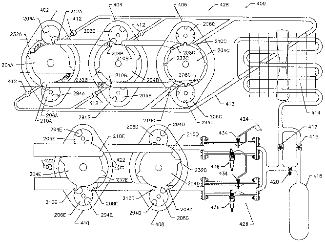
Turning now to the engine 400 constructed according to the
aforementioned first preferred embodiment, a schematic overview of same is
shown as Figure 1.
From the overview, this engine 400 will be seen to comprise a first
compression stage 402, a second compression stage 404, a third compression
stage 406, a positive displacement air motor 408 and a positive displacement
gas
expander 410. Each of these elements take the form of a rotary device as
previously described, and in fact, the exemplary rotary device described is
one
io and the same as that of the second compression stage 404. As these rotary
devices are generally similar in operation and structure, a detailed
description of
each is not provided herein. Rather, it should simply be understood that
equivalent structures in each of the rotary devices share a common numeric
identifier, and that the alphabetic identifier of the structures denote the
device in
i5~ question, as follows: first compression stage (A), second compression
stage (B),
. third compression stage (C), air motor (D) and gas expander (E}. Thus, since
the
housing plate.in the example was identified with the reference numeral 214B,
the
housing plate for the air motor is 214D. Similarly, since the piston in the
example
was identified with 2048, the piston for the third compression stage 406 is
2o identified 204C.
In addition, it should be presently understood that each of these elements
share a common drive shaft 314 and gate rotor shafts 316, and further, share
divider and bearing plates 216,218,220, 222, 223, 224, 226, 228, in the
context of
adjacent rotary devices. Thus, the housing means of the rotary device 200A of
2s the first compression stage 402 is defined by bearing plate 216, divider
plate 218
and housing plate 214A. Divider plate 218 also forms part of the housing means
. of the rotary device 200B of the second compression stage 404, in
combination
with divider plate 220 and housing plate 2148. Divider plate 220, divider
plate
222 and housing plate 214C form the housing means of the rotary device 200C of
3 o the third compression stage 406. Bearing plate 224, housing plate 214D and
divider plate 226 form the housing means of the rotary device 200D of the air
motor 408. Similarly, housing plate 226, housing plate 214E and bearing plate
228 form the housing means of the rotary device 200D of the gas expander 410.
AMENDED SHEET
CA 02552819 2006-07-06
' - 14 -
For clarity, bearing plates 216,224 and 228 include bearings 324 for rotatably
supporting the drive shaft 314. Only housing plate 218 is shown in detail in
the
drawings, but it should be understood that the other housing plates 220,222
and
226 are substantially similar thereto, differing substantially only in the
size and
shape of ports therein. The construction of such bearing plates 220,222 and
226
will be routine to persons of ordinary skill in the art, having regard, inter
alia, to
the demarcation of the ports 208,210 in Figures 4,6,7,9 and 10. Bolts 800,
shown in Figure 2, secure the assembly together.
From the overview, the engine will further be seen to comprise two sets of
to check valves 412, a manifold 413, a radiator 414, a pair of back-flow
preventers
416,417, a pressure tank 418, a solenoid valve 420, a pair of vacuum relief
valves 422, a fuel pump 424 and a tandem tubular combuster 426.
With reference to Figures 3 and 4, the rotary device 200A of the first
compression stage 402 operates as a compressor, and its piston 204A has four
i5 lobes 232A. With reference to Figures 3 and 6, the rotary device 2008 of
the
second compression stage 404 also operates as a compressor, with its piston
2048 having four lobes 2328, but differs, in that its piston 2048 is thinner
and its
lobes 2328 are smaller than in the first compression stage 402. The piston
2048
also has a diameter smaller than the diameter of the piston 204A in the first
2 o compression stage 402. With reference to Figures 3 and 7, the rotary
device
200C of the third compression stage 406 also is configured for operation as a
compressor. However, in contrast the pistons 204A,204B of the first 402 and
second 404 compression stages, this piston 2040 has eight lobes 232C, and is
even thinner than the piston 2048 of the second compression stage 404.
2s Further, the gate rotors 206C of the third compression stage 406 each have
four
sockets 294C, in contrast to the pairs of sockets 294A,294B formed in the gate
rotors 206A, 2068 of the first 402 and second 404 compression stages.
The. first 402, second 404 and third 406 compression stages together
define a compressor 428, identified in Figure 1, that is adapted to receive
power
3o from the drive shaft 314 and, upon receiving power, to: periodically define
a
chamber; fill the chamber with ambient air; and carry out a pressurization
process
wherein the chamber volume is decreased to produce pressurized air. More
particularly, the inlets 208A of the first compression stage 402 are coupled
to an
AMENDED SHEET
CA 02552819 2006-07-06
' - 15 -
air~filter 438 by means of a bifurcated intake duct 440 to receive filtered
ambient
air, as shown in Figure 2; the outlets 210A of the first compression stage 402
are
coupled to the inlets 208B of the second compression stage 404, as shown in
Figure 1 and Figure 5; and the outlets 2108 of the second compression stage
404 are coupled to the inlets 208C of the third compression stage 406, as
shown
in Figure 1. This provides a direct flow path from the inlets 208A of the
first
compression stage 402, which receive ambient air, to the outlets 210C of the
third compression stage 406, which deliver air to the manifold 213. It is
noted at
this time that the chamber defined periodically by the compressor 428 is
defined
1o initially by the first compression stage 402, and thereafter, by the second
404 and
third 406 compression stages, as it decreases in volume.
The use of a staged compression is advantageous, as is readily
understood by persons of ordinary skill in the art, since it lessens the
pressure
differential faced by any single stage, and thereby greatly facilitates the
manner
of sealing.
The check valves 412 are coupled to the outlets 210A, 2108 of each of the
first 402 and second 404 compression stages, as shown in schematic form in
Figure 1. The manner of such coupling in this preferred embodiment will be
readily understood from a review of Figure 5 and Figure 6. Figure 5 shows
2o divider plate 218, and shows two passages, each leading between a
respective
. port 208B and port 210A. Two additional passages are shown, each leading
between port 210A and port 215. Ports 215, in turn, are shown in Figure 6 to
lead to the manifold 413 through respective check valves 412. Ports 215 are
also
shown in Figure 4, and function similarly. Such coupling of the check valves
412
to the manifold 413 provides an alternate flow path, if the pressure in the
manifold
413 is less than the pressure at the outlets 210A,210B. That is, some portion
of
the gas exiting the outlet.210A of the first compression stage 402 will pass
into
the manifold 413 if of higher pressure than the contents of the manifold 413.
Similarly, some portion of the gas exiting the outlet 2108 of the second
3o compression stage 404 will pass into the manifold 413 if of higher pressure
than .
the contents of the manifold 413. The check valves 412 of this preferred
embodiment are of the simple spring-biased ball-in-socket variety well-known
to
persons of ordinary skill in the_art, and as such, are not described in detail
herein.
AMENDED SHEET
CA 02552819 2006-07-06
' - 16 -
With reference to Figure 1, the radiator 414 is coupled to the manifold 413
n to receive air therefrom, and is a vessel of high surface area relative to
its volume
which is adapted to permit heat generated in the course of pressurization to
be
transferred to ambient air. Importantly, the radiator 414 also functions as a
s reservoir of cooled pressurized air.
The first backflow preventer 416 and the second backflow preventer 417 _
are each coupled to the radiator 414 to permit unidirectional flow therefrom.
The pressure tank 418 is coupled to the first backflow preventer 416 to
receive pressurized air from the radiator 414.
1o The solenoid valve 420 is coupled to the.ptessure tank 418 to permit the
selective release of cooled pressurized air from the pressure tank,418.
With reference to Figures 1 and 11a-d, the tubular combuster 426 is
coupled to the solenoid valve 420 and to the second backflow preventer 417 to
receive pressurized air from the radiator 414 and pressurized air selectively
1s released from the pressure tank 418 and is adapted to receive fuel and
combust
same in a combustion process with the pressurized air so received to produce
primary exhaust products. Thus, the tubular combuster 426 defines combuster
means for receiving fuel and combusting same in a combustion process with the
pressurized air to produce primary exhaust products. ~ In the preferred
2o embodiment illustrated, the. tubular combuster 426 is a ceramic lined
tubular
combuster. The construction of tubular combusters is known to persons of
ordinary skill in the art and as such is not detailed herein. In the tubular
combuster 426, fuel is introduced via fuel injectors 434, and combustion is
initiated by an igniter 436, which takes the form of a conventional spark
plug.
2s The fuel pump 424 of this preferred embodiment of the engine. 400 has
specific characteristics which provide for effective operation of the engine
400.
Firstly, the fuel pump 424 provides the fuel to the fuel injectors 434
substantially
continuously, to provide for a substantially constant pressure bum. Further,
it is
synchronized with the drive shaft 314 to provide a fixed volume of fuel to the
3 o combuster 426 for each revolution for a given steady state load and is
capable of
increasing or decreasing this volume to meet changes in loading. Yet further,
it
delivers a uniform flow at sufficient pressure to achieve atomization even
when
AMENDED SHEET
CA 02552819 2006-07-06
' - 17 -
flow rates are very low. As well, it is capable of handling fuels that have
little or
s no lubricating properties such as alcohol.
A view of the fuel pump 424 of Figure 2 is shown in Figure 20a, with a
cover plate 536 thereof removed, for clarity, to reveal a pump block 538
which, in
use, is bolted to the engine block in overlying relation to the end of a gate
rotor
shaft 316. The pump block 538 defines an inlet port 502, an outlet port 506
and a
pump chamber 504. A keyed rotor 544 is shown in isolation in Figure 20n. The
rotor 544 extends through the pump block 538 into a keyed bore (not shown)
formed in the end of the gate rotor shaft 316, and is secured thereto by a key
(not
so shown). This provides for rotation of a rotor head 512 of the rotor 544 in
the
pump chamber 504 contemporaneously with rotation of the gate rotor shaft 316.
Fuel enters through the inlet port 502, passes through the pump chamber 504
and exits through the outlet port 506. The fuel is swept through the chamber
504
by three moveable vanes 508 set in slots 510 in the rotor head 512. A throttle
slide 514 is shown in isolation in Figs. 200, 20p. The slide 514 is fitted far
sliding
movement in a chase formed in the pump block 538. The volume of the pump
chamber 504 is changed by moving the throttle slide 514 towards or~ away from
the face of the rotor by means of screw threads on a throttle shaft 516, which
rotates in the end plate 518. The face of the throttle slide 514 is a partial
2o cylindrical surface that matches the face of the rotor head 512. Thus, the
volume
in the pump chamber 504 can be reduced t0 zero when the throttle slide 514 is
fully advanced. A passage 520 runs from the inlet port 502 to .the top of the
pump block 538 where it intersects an L-shaped groove 522 in the cover plate
536. This permits any fuel that might leak past the throttle slide 514 to be
drawn
back to the inlet port 502. A similar passage 524 at the outlet port 506
connects
to a groove 526 in the cover plate 536. This supplies pressurized fuel to the
circular groove 528 in the top of the rotor 544 thereby forcing the vanes 508
into
contact with the face of the throttle slide 514.
With reference to Figures 1 and 9, the rotary device 200D of the air motor
408 is configured for operation as an expander, and is coupled t0 the tubular
combuster 426 so as to be driven by the primary exhaust products to produce
power and secondary exhaust products, removing a fixed volume of gas from the
combuster 426 for each rotation of the shaft 314. In Figure 9, fluid ports
208D
AMENDED SHEET
CA 02552819 2006-07-06
- 18 -
. are each shown coupled to a respective halve of combuster 426. The piston
., 204D of the rotary device 200D of the air motor 408 has four lobes 232D,
and is
similar in dimension to that of the second compression stage 404.
With reference to Figures 1 and 10, the rotary device 200E of the gas
expander 410 operates as an expander and is coupled to the air motor 408 for
receiving the secondary exhaust products and expanding same substantially
adiabatically to produce tertiary exhaust products and power. The piston 204E
of
the gas expander 410 has four lobes 232E, and is wider than the rotors
204A,204B,204C of the compressor, so as to provide a greater expansion
1o volume than compression volume in the engine 400.
The vacuum relief valves 422 are provided to permit communication
between the atmosphere and the interior of the gas expander 410 when the
interior pressure threatens to fall beneath atmospheric pressure, and
communicate with the inlets 208E via respective vacuum ducts 425. The
. vacuum relief valves 422 of this preferred embodiment are constructed
similarly
to the aforementioned check valves 412 known to persons of ordinary skill in
the
art, and are for similar reasons not described in detail.
The shaft 314, which as aforesaid is shared by each of the compressor
428, the air motor 408 and the gas expander 410, will thus be seen to define
2o power transfer means for directing power produced by the air motor 408 and
the
gas expander 410 in use ~to drive the compressor 428 and any external load.
In addition to the foregoing, an oil circuit is provided, in the form of an
oil
pump 700, shown in Figure 2, which is coupled to a sump 714. Oil drawn from
sump 714 is circulated through oil supply line 702 to distribution conduits
706
formed in the top of the engine 400, above the shafts 314,316, as shown in
Figure 4. Lubrication channels 708 in the housing plates 214A,B,C,D,E lead
from
the distribution conduits 706 to central bores through which, inter olio, the
shafts
314,316 pass. Distribution heads 710 receive oil from lubrication channels
708, .
and direct flow longitudinally, against longitudinally-adjacent pistons 204.
3 o Distribution conduits 708 also feed bearings (not shown) for the gate
rotor shafts
316. Additionally lower distribution conduits 706 are formed in the bottom of
the
engine 400, beneath the shafts 314,316. Also provided are additional
lubrication
channels 708 which collect oil from the bores, and, via drains 709, from
AMENDED SHEET
CA 02552819 2006-07-06
.. - 19 -
longitudinally adjacent bearings, for delivery to the tower distribution
conduits
706, and subsequent return to the sump 714, for reuse. A conventional oil
cooler
(not shown) is provided, and utilized as necessary to withdraw heat from the
oit.
The oil pump 700 shown in Figure 2'is of similar appearance to the fuel pump
s previously described, but it should be understood that this is mere
coincidence;
any conventional oil pump may be employed.
Steady State Operation
In operation at steady state conditions, the pressure in the radiator 414
and at the inlet of the combuster 426 is substantially constant. (Among other
so things, minor flow-induced pressure gradients may develop in the ducts and
valves of the device, and periodic minor fluctuations in pressure may result
from
the manner in which compression takes place, namely, periodically.) It should
be
understood that this constant is not an absolute constant, but rather, varies
with,
among other things, the load being driven by the power transmitted by the
shaft
314. Ambient air is drawn into the compressor 428 and forced into the radiator
414, in the manner described previously. It should be noted ,at this time
.that the
close spacing of the lobes 232C of the third compression stage 406 ensure that
through a substantial portion of their sweep air is trapped between two lobes
232C moving in tandem, rather than between a gate rotor 206C and an
2o approaching lobe 232C. Thus, the third compression stage 406 in this
example
functions both to add some compression, to prevent any back flow that would
lead to pressure fluctuations in the radiator 414 and smooth pressure spikes.
The mass of the air forced into the radiator 414 is a function of the
rotational rate
of the shaft 314, the volume swept by the lobes 232A in the first compression
25 stage 402 and the ambient pressure and temperature. Similarly. the mass of
air
leaving the combustor is a function of the rotatianal rate of the shaft 314,
the
volume swept by the lobes 232D , in the air motor 408 and the pressure and
temperature within the combustor. During steady state operation the two masses
must be equal.
3 o In contrast to a conventional piston-cylinder engine, air will not be
compressed to any maximum compression set by the compressor before ingress
to the compressor. Rather, since the chambers defined by the compressor 428
wherein pressurization is occurring are in fluid communication with the
radiator
AMEN~ED SHEET
CA 02552819 2006-07-06
- 20 -
414 at all times, air will be compressed into the radiator 414 only against
the
r pressure of the radiator 414. Air will issue from the radiator 414 at a mass
flow
rate equivalent to that entering the radiator 414, pass through the check
valve
417 and to the inlet of the combuster 426, where it is mixed with fuel and
s combusted to produce primary exhaust products. The pressure in the combuster
426 will be substantially constant, although slight fluctuations may occur,
.from the
manner in which expansion is accommodated, namely, periodically. This
pressure will also be a function of, among other things, the load on the shaft
314,
and will be marginally less than the radiator 414 pressure. The residence time
of
io the fuel in the combuster 426 is such that most of the fuel is combusted,
and the
temperature is such that NOx emissions are relatively low. The primary exhaust
products pass through the air motor 408, producing shaft power, and exit as
secondary exhaust products. The secondary exhaust products .are expanded
substantially adiabatically in the expander 410 to produce tertiary exhaust
15 products and shaft power. The secondary exhaust products exit the expander
410 near atmospheric pressure, such that most work has been extracted
therefrom, and to reduce the need for resonators and mufflers. To the extent
that
there exists any excess expansion space in the expander 410, the vacuum relief
valves 422 permit flow of ambient air into the expander 410, so as to avoid
the
2o creation of a vacuum.
Transitioning to New Loads
When transitioning from a relatively heavy load to a relatively fight load,
the fuel flow rate will be decreased, thereby to create less heat in the
combuster
426, less increase in the volume of the air being heated and lower pressures.
2s The lower pressure in the combuster 426 will increase flow from the
radiator 414
until such time as the pressure in the radiator 414 has dropped to a point
that it is
only sufficiently great to force flow into the combuster 426 at the same rate
as it
is delivered by the compressor 428. The depressed radiator 414 pressure will
result in relatively more air bypassing the second compression stage 404
and/or
3 o the first compression stage 402, with the result that less work will be
exerted on
the gas. It will thus be evident that the effective compression ratio of the
engine
400 will spontaneously adjust downwardly in response to tower loads.
AMENDED SHEET
CA 02552819 2006-07-06
- 21 -
When transitioning from a relatively light load to a relatively heavy load,
the fuel flow rate will be increased, thereby to create more heat in the
combusters
426 and higher pressures. Again, fuel will be introduced into the tubular
combuster 426 in a manner which will provide for substantially constant
pressure.
The higher pressure in the combusters 426 will temporarily decrease flow from
the radiator 414, thereby resulting in a pressure increase in the radiator
414. The
increased pressure in the radiator 414 will increase flow to the tubular
combuster
426, and, to the extent that the pressure in the pressure tank 418 is below
the
radiator 414 pressure, will result in flow into the pressure tank 418. This
situation
to will occur until a steady state is reached wherein the pressure in the
radiator 414
has risen to a point sufficiently great to force flow into the tubular
combuster 426
at the same rate as it is delivered by the compressor 428. The heightened
radiator 414 pressure will result in relatively less air bypassing the first
compression stage 402 and/or the second compression stage 404, with the result
i5 that more work will be exerted on the gas, to wit, enough to force the gas
into the
relatively higher pressure radiator 414. It will thus be evident that the
effective
compression ratio of the engine will spontaneously adjust upwardly in response
to higher loads.
With regard to transitions to higher loads, stalling can occur in the context
20 of rapid load increase, since constant flow to the engine would require a
corresponding rapid increase in radiator pressure. To avoid this consequence,
air can be released from the pressure tank 418 by opening the solenoid valve
420.
Pressurized air from the air tank 418 can also be used to start the engine,
25 in the place of a conventional starter. With respect to starting, it should
also be
noted that, when the engine is not operating, the pressure in the radiator 414
and
combuster 426 will be at or near atmospheric pressure. Accordingly, with the
engine decoupled from any external load, relatively little force will be
required to
rotate the shaft 314 for starting, since much of the ambient air being drawn
into
3 o the compressor 428 will not be pressurized to any great extent, and will
pass
more or less directly to the radiator 414, against very little back pressure,
and
therefrom, into the combuster 426, against very little back pressure.
Dimensions
AMENDED SHEET
CA 02552819 2006-07-06
22
The various components of the engine are constructed to meet the
!, anticipated demands of the engine and the fuel upon which it will operate.
In the
context of an engine which will drive a constant load, the expansion volume
will
be sufficient to make proper use of the energy contained in the fuel, such
that
expansion gases contain very little energy. That is, the exhaust gases will
exit at
as close to atmospheric pressure as is practical. With respect to compression
volume and ratio, this needs to be sufficient to meet the oxygen demands of
the
engine at the operating pressure.
If the range of the engine will not operate at constant loading, the normal
io operating range of the engine will need to be considered. At peak fuel
toad, the
engine will operate at peak compression, and will need more expansion volume
than when the engine is .running under lower loads. Thus, an engine designed .
for an application requiring a narrow operating range should have a larger
expansion to compression ratio than an engine designed for a wider operating
range. .
The incorporation of the vacuum relief valve 422 in the expander 410
helps to prevent unnecessary drag on the piston 204E when the engine 440 is
operating at low fuel loads. However, for an engine that frequently operates
under low load conditions, it may be' desirable to strike a balance
incorporating
2o somewhat less expansion volume. For example, in an engine which is expected
to operate under a wide load range, it may be desirable to have the expansion
to
compression ratio optimized for a 75% fuel load. Thus, when the.engine is
under
-peak load, the expansion volume will be somewhat inadequate. Conversely,
when the engine is under low load, the expansion volume will be somewhat too
2s large. Nevertheless, across the range of operating loads for that specific
application, optimizing for a 75% fuel load could prove the best solution in
terms
of overall efi~iciency. .
Second Preferred Embodiment
A second preferred embodiment of an engine according to the present
3 o invention is illustrated in Figures 21-26. Components of this engine which
correspond to those of the first preferred embodiment are provided with
identical
reference numerals. As will be evident to persons of ordinary skill in the
art, this
engine is generally similar to that of the first preferred embodiment, and
thus, a
AMENDED SHEET
CA 02552819 2006-07-06
s
- 23 -
detailed description of its. components and operation is neither needed nor
provided herein. Rather, for simplicity, only the differences in structure and
operation are herein set out. .
From the standpoint of structure, this engine lacks a third compression
s stage, and includes only two ~ pistons, in contrast to the previous
embodiment,
wherein five pistons were used. Further, wherein in the previous embodiment
the
gate rotors were disposed 180° apart from one another relative to the
drive shaft,
herein, the gate rotors are about 130° apart from one another, such
that the
chambers defined on either side thereof are not of equal volumes. As well, in
this
1o configuration, no external combuster is provided, and a simple reservoir
414A is
provided in the place of the radiator. Additionally, an inlet valvelfuel
injection port
600 herein is controlled by a lifter rod 601 which runs on an inlet valve
control
groove 602 in the second rotor. This mechanism forces the inlet valve/fuel
injection port 600 closed while the lobe is passing through the gate rotor.
The
15 inlet valve/fuel injection port 600 in this example configuration is
designed to
introduce fuel to the first expansion chamber as well as compressed air. The
inlet vaive/fuel injection port 600 has a hollow valve stem (not shown) that
rides
over a valve stem centre pin (also not shown) that in turn has a central
cavity
extending almost to the first expansion chamber. Outlet ports in the valve
stem
2 o and valve stem centre pin will only align when the inlet valve/fuef
injection port
600 is open, allowing fuel to enter and mix with the incoming air. A glow plug
609, or spark plug, if appropriate to the fuel, is placed just downstream of
the inlet
valve/fuel injection port 600. A primary exhaust valve-605 coupled with a
primary
exhaust valve lifter 606 running in the second expansion chamber inlet, valve
. 25 control groove 607 controls the inlet to the second expansion chamber.
This
mechanism prevents combusted gases from entering until the gate rotor recess
is
clear of the chamber. This mechanism will also prevent the gases from escaping
directly to the atmosphere when both the inlet and exhaust port are exposed.
In operation, air passing through this engine will enter a first compression
3 o stage 402, defined by the smaller volume side of the first piston, then
proceed to
a second compression stage 404, defined by the smaller volume side of the
second piston. From the second compression stage 404 the compressed air
flows through to the reservoir 414A, and thereafter to' the larger side of the
AMENDED SHEET
CA 02552819 2006-07-06
S
- 24 -
second rotor. Fuel is added directly into the chamber swept by the larger side
of
,,
the second rotor and combustion takes place. Thus, the larger side of the
second rotor serves as a combuster and as an air motor 40~. The pressure in
the combuster will rise on ignition forcing the inlet valve 600 to close.
While the
cam groove allows, and while the pressure in the reservoir 414A is greater
than
the pressure in the ~ first expansion stage 402, this valve 600 will open and
equalize the pressures. Thus, at low engine loads, with corresponding iow fuel
loads, the pressure in the first expansion stage will drop below the pressure
in the
reservoir 414A before the valve lifter reaches the end of the cam groove: In
this
io case more air will flow from the reservoir 414A into the combuster 426.
This will
drop the pressure in the air reservoir 414A until a state of equilibrium is
reached
at a compression ratio between the minimum and the maximum.
While the invention has been described in connection with just two
preferred embodiments, it will be understood by those skilled in the art that
other
i5 variations and modifications of the preferred embodiments described above
may
be made without departing from the scope of the invention.
For example, compression and/or expansion could bath be completed
using a larger number of steps than indicated in the preferred embodiments.
As well, other non-rotary configurations of the engine are possible. By way
20 of example, a first compression could be accomplished with a piston, with
the air
being piped to another location for secondary compression using a rotor.
Similarly, the expansion can be multi-staged, employ difFerent means from one
stage to the next, with the various stages taking place in different
locations.
Obviously the second preferred embodiment could be equipped with an
2 s external cambuster as described in the first preferred embodiment.
The engine can be -used with or without the pressure tank, depending on
whether the application would have to respond to rapid changes in engine load.
The pressure tank could also be charged via a separate compressor
mechanism. This separate cori~pressor could be another rotor group on the
3o existing main drive and gate rotor shafts, or an independent mechanism. In
these
cases, it becomes possible for the pressure in the tank to be higher than the
maximum compression ratio of the engine.
AMENDED SHEET
CA 02552819 2006-07-06
a,
v
' - 25 -
Water in the combustion chamber could keep the heat of combustion from
getting too high, and would provide additional expansion volume. Since the
exhaust gases would typically undergo an adiabatic expansion to atmospheric
pressure, it would be a simple matter to capture and recycle condensed
injection
s water. Another option would be to inject the water during compression. The
added' heat sink effect of the water makes the compression more closely
resemble an isothermal compression. This has advantages over an adiabatic
compression in that the result is relatively cool dense air which is ideal for
maximizing efficiency.
to A small simple engine could be built using only a single pair of gate
rotors
working in concert with a single multilobe piston.
The engines of the preferred embodiments are capable of switching
between a wide variety of liquid fuels without modification. Similarly,
switching
from one gaseous fuel to another should be relatively simple. However,
15 modifications to fuel pumps and possibly injectors would likely be required
to shift
back and forth from liquid to gaseous fuels. Such modifications are known to
persons skilled in the art, and as such, are not described in detail herein.
Explosive fuels, may be used, provided fuel is introduced gradually. For
slower
burning fuels, fuel could be introduced in bursts.
2 o From the above, it should therefore be understood that the scope of the
present invention is limited only by the following claims, purposively
construed.
AMENDED SHEET