Note: Descriptions are shown in the official language in which they were submitted.
CA 02552961 2006-07-07
DESCRIPTION
HYDROGEN OR HELIUM PERMEATION MEMBRANE AND STORAGE
MEMBRANE AND PROCESS FOR PRODUCING THE SAME
TECHNICAL FIELD
The present invention relates to hydrogen permeation membrane used mainly in
electrolytic capacitors, fuel cells, the purification of hydrogen, and solar
cell systems.
The invention also relates to hydrogen storage membrane used for the storage
and
transport of energy via the fuel tank of a hydrogen vehicle or a chemical heat
pump.
The invention also relates to a method for the production of such membranes.
BACKGROUND ART
Several processes are known for the production of hydrogen, such as processes
involving the breakdown of water, ammonia, and methanol, and the steam
reforming of
hydrocarbon gas. For example, when hydrocarbon gas and water vapor are
reformed at
high temperature, not only hydrogen but also carbon monoxide CO, carbon
dioxide COZ,
unreacted water vapor H20, and hydrocarbon, such as methane CH4, are produced.
Thus, it becomes possible to efficiently purify or store hydrogen if there is
a
hydrogen permeation membrane or a hydrogen storage membrane that has a high
selectivity with respect to the aforementioned gases such as carbon monoxide
CO,
carbon dioxide C02, water vapor H20), and methane CH4. Gas separation
membranes
for separating hydrogen gas from other gases are required to have high gas
permeability,
and a high ability to separate hydrogen and other gases (such as methane).
They are
also required to have such properties that a membrane without defects, such as
pin holes,
can be easily made, and stable performance is obtained in the environment
where it is
used. They also need to withstand long-time use, have good resistance to
pressure, can
be constructed in modules, and have superior resistance to heat and chemicals.
Conventionally, a palladium membrane is well known as a membrane that
selectively
1
CA 02552961 2006-07-07
allows hydrogen to permeate. Palladium, however, is very expensive, and
because a
palladium membrane is a thin film, it is not resistant to pressure and it also
has chemical
resistance problems. Furthermore, because palladium needs to be used in the
form of a
thin membrane, it is difficult to obtain desired shapes, for example.
Commercially available membranes of organic material include (Product name:
cellulose acetate from Sepharex; Product name: polysulfone from Monsanto;
Product
name: polyimide from Ube Industries, Ltd.; polyamide from Dupont).
These are all glassy polymers having high glass transition temperatures, and
their hydrogen permeation selectivity with respect to methane is reported to
be in the
range of 40 to 200 (see Non-patent Document 1, for example). With reference to
a
prism separator consisting of an asymmetrical polysulfone hollow-fiber
composite
membrane from Monsanto as mentioned above, gases can be arranged as follows in
order of decreasing permeation rate: water vapor>hydrogen>helium>hydrogen
sulfide>carbon dioxide>oxygen>argon>carbon monoxide>nitrogen>methane. Major
gas molecules are arranged as follows in order of increasing size:
helium<water
vapor<hydrogen<carbon dioxide<oxygen<nitrogen<methane. Thus, the rate of
permeation through a separation membrane is determined not only by the size of
the
molecule but it also varies depending on the properties of the material of the
separation
membrane.
A technique is also published (see Patent Document 1, for example) whereby
silicon resin, which is a material used in the invention, is used in a
hydrogen permeation
membrane. The technique disclosed in this document involves the formation of a
membrane having a hydrogen permeation function, such as a membrane of silicon
resin,
on a porous support to a membrane thickness of 500 microns or less. With this
technique, however, it is difficult to obtain desired shapes, as in the case
of palladium
membrane, and it is also difficult to obtain modules or to achieve high
resistance to
pressure.
Regarding the processes for storing hydrogen, the existing technologies
involving high-pressure hydrogen gas cylinders, liquefied hydrogen cylinders,
hydrogen
2
CA 02552961 2006-07-07
absorbing alloy, carbon material, organic material, and so on are currently
used as
hydrogen storage media. With reference to high-pressure hydrogen gas
cylinders, for
example, development is underway of high-pressure cylinders of 700 atmospheres
for
automobiles equipped with fuel cells. With reference to hydrogen absorbing
alloy,
studies on LaNi5, for example, which is an alloy of lanthanum and nickel, are
actively
underway. One most suitable example of the utilization of the hydrogen storage
and
transfer technology is its application to hydrogen fuel tanks on fuel cell
vehicles.
Mobile media such as fuel cell vehicles require stable and safe supply of
hydrogen to the
cells. However, high-pressure cylinders have the danger of explosion or the
like, while
hydrogen absorbing alloy is capable of storing only a small amount of hydrogen
per unit
mass of the alloy. Thus, there are many problems to be overcome before these
technologies can be put to practical use.
Non-patent Document 1: "Separation Engineering," Advances in Chemical
Engineering
25, edited by The Society of Chem. Engrs, Japan, Maki-shoten
Patent Document 1: JP Patent Publication (Kokai) No. 2001-198431 A
DISCLOSURE OF THE INVENTION
PROBLEMS TO BE SOLVED BY THE INVENTION
The aforementioned conventional hydrogen permeation membranes, hydrogen
storage membranes, and processes for forming the same have the following
problems.
The hydrogen permeation mechanism of the palladium membrane involves a
dissolution
and diffusion mechanism accompanied by the dissociation of hydrogen. In order
to
increase the permeation rate up to the practical level, it would be necessary
to either
supply hydrogen gas at temperatures of 300 or higher and at several tens of
pressures,
or to reduce the membrane thickness to the order of several tens of microns.
In
addition, the palladium membrane, when coexisting with hydrogen, forms a kind
of solid
solution, the temperature of which would have to be increased to approximately
400 C
so as to increase the permeation rate. In other words, each time the hydrogen
3
CA 02552961 2006-07-07
permeating function is realized, heating and cooling are repeated. As a
result, due to
the accumulation of internal stress caused by the repetition of two-phase
separation into
two phases with different hydrogen concentrations and the re-emergence of the
state of
solid solution, the membrane tends to break. For example, in the case of a
thin
membrane of palladium or an alloy thereof formed by plating, evaporation,
sputtering or
rolling, pin holes tend to be formed. In order to avoid this problem, silver
or gold is
often added to the palladium in the amount of approximately 25%. Other
problems are
the fact that palladium itself is very expensive, and that a thin membrane of
palladium
needs to be formed on the surface of a heat-resistant porous support.
Hydrogen, water vapor, and helium molecules have substantially the same size.
For example, with regard to the hydrogen gas separation membrane to be used
when
reforming hydrocarbon with water vapor, the permeation rate of hydrogen needs
to be
sufficiently large as compared with that of water vapor. Thus, the membrane
needs to
have a practical level of hydrogen permeation selectivity, and it also needs
to be easily
formed, resistant to pressure, and sufficiently strong.
With regard to hydrogen storage material, there are many problems to be
overcome in conventional hydrogen storing alloys, such as their high price,
their weight
due to the fact that they are alloys (namely, their storage amount per unit
weight is
small), the deterioration due to the repetition of storage and discharge
(namely,
pulverization or the change in structure of the alloy), and, in the case where
the alloy
includes a rare metal, the need to ensure its resource.
It is an object of the invention to overcome the aforementioned problems of
the
conventional art, and to provide a hydrogen or helium permeation membrane that
substantially does not contain expensive metal having affinity with hydrogen.
The
membrane has superior pressure, heat, and chemical resistance and mechanical
strength.
It also has a high permeability with respect to hydrogen, the membrane further
having
the following properties: (1) it allows the passage of hydrogen more easily
than water
vapor; (2) it does not easily allow the passage of methane; and (3) it does
not easily
allow the passage of ammonium gas. The invention can be applied to a hydrogen
4
CA 02552961 2006-07-07
separation membrane obtained by the reforming reaction of water vapor and
hydrocarbon, to an external film of secondary cells such as lithium cells, and
to a
hydrogen permeation membrane used in electrolytic capacitors, fuel cells, and
solar cell
systems.
It is another object of the invention to provide a hydrogen permeation
membrane such that the permeation ratio can be controlled by the baking
temperature,
membrane thickness, or through additives such as Aerosil, wherein the membrane
is
inexpensive and easy to manufacture, having a high degree of freedom in
membrane
thickness ranging from a thin membrane of several m to a thick membrane of
several
mm, and wherein the membrane can be processed in any desired form, including
tubes,
sheets, bulk, and fiber (threads).
Another object of the invention is to provide a hydrogen storage membrane that
does not have the aforementioned problems and that is capable of storing
hydrogen
under normal temperature and pressure conditions, allowing hydrogen to be
handled
safely. Such hydrogen storage membrane enhances the application of fuel cells
as a
power supply for electric vehicles to hydrogen storage tanks or the like.
MEANS FOR SOLVING THE PROBLEMS
As a result of extensive research and study for solving the aforementioned
problems, the inventors realized that by using, as a hydrogen permeation
membrane that
selectively allows the passage of hydrogen and that can be formed in any
desired shape,
a silicon resin containing at least phenylheptamethylcyclotetrasiloxane and/or
2,
6-cis-diphenylhexamethylcyclotetrasiloxane, a coating that is resistant to 300
C or
higher can be obtained in a sintering process with heat treating temperature
of 200 C to
500 C, whereby a hydrogen permeation membrane having excellent water
resistance can
be obtained. The invention is based on such realization.
Similarly, the inventors arrived at the invention after realizing that, by
using, as
a hydrogen permeation membrane that selectively stores hydrogen and that can
be
formed in any desired shape, a silicon resin containing at least
CA 02552961 2008-09-04
phenylh.eptamethylcyclotetrasiloxane and/or 2,
6-cis-diphenyihexanlethylcyclotetrasiloxane, a coating resistant to 300 C or
higher can
be obtained in a sintering process with heat treating temperature of 200 C to
500 C,
whereby a hydrogen storage membrane having excellent water resistance can be
obtained.
Nainely, the invention is directed to the following:
1) A hydrogen or helium permeation membrane comprising a silicon resin that
includes at least phenylheptamethylcyclotetrasiloxane and/or 2,
6-cis-diphenylhexamethylcyclotetrasiloxane.
2) The hydrogen or helium permeation membrane according to para=. 1, wherein
the silicon resin that includes at least phenylheptamethylcyclotetrasiloxane
and/or 2,
6- cis -diphenyl hexam etliyl cyclotetrasi loxane contains a metal or oxide
particle.
3) The hydrocren or helium permeation membrane according to para. 2, wherein
the metal or oxide particle comprises a particle or ultrafine particle of Al,
Ti, Si, Ag, or
the like, a filler comprising a particle of alumina, titanium oxide, Si02, or
the like, and
an ultrafine particle silica or the like.
4) The hydrogen or helium permeation membrane according to any one of
paras. 1 to 3, wherein the hydrogen permeation membrane is thermally cured at
temperature of 200 C to 500 C after being adjusted to a desired viscosity at
temperature
of 230 C or lower into a precursor.
5) The hydrogen or helium permeation membrane according to para. 4, wherein
the precursor and the hydrogen permeation membrane are subjected to a vacuum
heating
process at least once at a temperature lower than or equal to a temperature at
which the
hydrogen permeation membrane is cured.
6) A method for forming a hydrogen or helium permeation membrane
comprising the steps of:
causing a metal or oxide particle to be contained in a silicon resin that
includes
at least phenylheptamethylcyclotetrasiloxane and/or 2,
6-cis-diphenylhexamethylcyclotetrasiloxane, to which resin a metal or oxide
particle is
6
CA 02552961 2008-09-04
contained, and then forminp a precursor having a desired viscosity at
temperature of
230 C r lower; and
thermally curing the precursor at temperature of 200 C to 500 C.
7) The method for forming a hydrogen or helium penneation membrane
according to para. 6, wherein the metal or oxide particle comprises a particle
or
ultrafine particle of Al, Ti, Si, Ag, or the like, a filler comprising a
partiele of alumina,
titanium oxide, Si 2, or the like, and an ultrafine particle silica or the
like.
8) The method for forming a hydrogen or helium permeation membrane
according to para. 7, wherein the step of forming the precursor and the
hydrogen or
helium permeation memhrane comprises performing a vacuum thermal process at
least
once at a temperature lower than equal to a temperature at which the hydrogen
or helium
permeation membrane is cured.
9) A hydrogen or helium storace membrane comprising a silicon resin that
includes at least phenylheptarnethylcyclotetrasiloxane and/or 2,
6-cis-diphenylhexamethylcyclotetrasiloxane.
10) The hydrogen or helium storage membrane according to para. 9, wherein
the silicon resin that includes at least phenylheptamethylcyclotetrasiloxane
and/or 2,
6-cis-diphenylhexameth.ylcyclotetrasiloxane comprises a metal or oxide
particle.
11) The hydrogen or helium storage membrane according to paxa- 10, wherein
the metal or oxide particle comprises a particle or ultrafine particle of Al,
Ti, Si, A;, or
the like, a filler comprising a particle of alumina, titanium oxide, Siaz, or
the like, and
an ultrafine particle silica or the like.
12) The hydrogen or helium storage membrane according to para. 10 or 11,
wherein the hydrogen storage membrane is thermally cured at temperature of 200
C to
50t4 C after being adjusted to a desired viscosity at temperature of 230 C or
lower into a
precuror.
13) The hydrogen or helium storage membrane according to para= 10, wherein
the precursor and the hydrogen or helium storage membrane is subjected to a
vacuum
heating process at least once at a temperature lower than or equal to a
temperature at
7
CA 02552961 2008-09-04
which the hydrogen or helium storage membrane is cured.
14) A method for forming a hydrogen or helium storage membrane comprising
the steps of:
forming a precursor having a desired viscosity at a temperature of 230 C from
either a silicon resin that includes at least
phenylheptamethylcyclotetrasiloxane an(:lor 2,
6-cis-diphenylhexamethylcyclotetrasiloxane, or silicon resin that includes at
least
phenylheptamethylcyclotetrasiloxane and/or 2,
6-cis-diphenylhexamethylcyclotetrasiloxane, to which resin a metal or oxide
particle is
contained; and
thermally curing the precursor at temperature of ?00 C to 500 C.
15) The method for forming a hydrogen or helium storage membrane according
to para. 10, wherein the metal or oxide particle comprises a particle or
ultrafine particle
of Al, Ti, Si, Ag, or the like, a filler comprising a particle of alumina,
titanium oxide,
Sit7z, or the like, and an ultrafine particle silica or the like.
16) The method for forming a hydrogen or helium storage membrane according
to para- 10, wherein the step of fornning a hydrogen or helium storage
membrane
comprises performing a vacuum heating process at least once at a temperature
lower
than or equal to a temperature at which the hydrogen or helium storage
membrane is
cured.
EFFECTS OF THE INVENTION
As will be apparent from the above, in accordance with the invention, a
hydrogen or helium permeation membrane having a desired membrane thickness of
1
m or less to several mm and having pressure resistance, heat resistance of 300
C or
higher, and excellent chemical resistance can be easily formed by using a
precursor
comprised of a silicon resin containing at least
phenylheptamethylcyclotetrasiloxane
and/or 2, 6-cis-diphenylhexamethylcyclotetrasiloxane.
Further, in accordance with the invention, a precursor paste is obtained of
which
the viscosity is adjusted at a temperature of 230 C or lower to a desired
level. The
8
CA 02552961 2006-07-07
precursor paste is thermally cured at temperature of 200 C to 500 C. After
conducting
a vacuum heating process at least once at temperature lower than a temperature
at which
the hydrogen permeation membrane is cured, the precursor paste is formed in a
desired
shape. In this way, a hydrogen or helium permeation membrane that does not
have
many cracks, much warping, or interlayer peeling or the like can be easily
prepared.
Further, in accordance with the invention, by adjusting the viscosity as
needed
by appropriately selecting and setting the temperature and time, a hydrogen or
helium
permeation membrane having a desired performance can be formed.
The permeation membrane of the invention allows the passage of hydrogen gas
with high selectivity in the presence of water and gases that are produced as
by-products
in the course of hydrogen manufacturing process, such as carbon monoxide,
carbon
dioxide, methane, ammonium, and the like. In addition, the permeation membrane
has
excellent heat resistance and chemical resistance, and it can be used for
applications at
temperature of 300 C or higher.
Further, the hydrogen or helium storage membrane of the invention is capable
of
storing hydrogen with high efficiency under room temperature and pressure
conditions.
Thus, application of the hydrogen or helium storage membrane to a hydrogen
fuel tank
or the like of fuel cells as the power supply for electric vehicles can be
enhanced, thus
providing great benefits.
BRIEF DESCRIPTION OF THE DRAWINGS
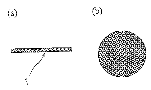
Fig. 1 shows a cross section (a) and a plan view (b) of an example of a
hydrogen
permeation membrane of the invention.
Fig. 2 shows a cross section (a) and a plan view (b) of an example of a
hydrogen
storage membrane of the invention.
Fig. 3 shows a schematic plan view of a vacuum apparatus for defoaming a
precursor.
Fig. 4 shows a schematic side view of an apparatus for measuring the presence
or absence of permeation or storage of hydrogen.
9
CA 02552961 2006-07-07
Fig. 5 shows a schematic side view of an apparatus for measuring the presence
or absence of permeation or storage of hydrogen.
BEST MODES FOR CARRYING OUT THE INVENTION
The invention is described in detail in the following.
(Hydrogen or helium permeation membrane)
The hydrogen or helium permeation membrane used in the invention employs,
as raw material, phenylheptamethylcyclotetrasiloxane and/or 2,
6-cis-diphenylhexamethylcyclotetrasiloxane, and silicon resin. Their stock
solutions,
or their solutions in an organic solvent such as toluene or xylene, are
prepared, and their
viscosity is adjusted for the membrane thickness and the coating method used,
so as to
prepare a precursor. Further, stock solutions of
phenyiheptamethylcyclotetrasiloxane, 2,
6-cis-diphenylhexamethylcyclotetrasiloxane and silicon resin as raw material,
or their
solutions in an organic solvent such as toluene or xylene, are prepared, and a
filler
consisting of ultrafine powder silica, oxide particles of e.g. alumina or
titanium, and
Si02 fine particles is added. After adjusting the viscosity, a precursor is
prepared.
In the case of membrane thickness on the order of several gm or less, the
viscosity is adjusted to several cps to 100 cps. In the case of membrane
thickness of
several m or more, heating is further conducted at 60 to 150 C for 2 to 5
hours such
that condensation reaction proceeds while the solvent is evaporated. Further,
while
evacuating in a vacuum chamber, a defoaming process is conducted in reduced
pressure
of 100Pa to IPa, and the viscosity of the reaction product is adjusted to 100
cps to
10000 cps, thereby obtaining a precursor paste.
The thus viscosity-adjusted precursor is cast-molded into a desired shape by a
known method such as one involving a dispenser, spraying, or screen printing,
for
example. The molded product is then heated in the atmosphere at 350 C so as to
allow
a hydrogen or helium permeation membrane to be cured. The degree of vacuum
during
the defoaming process is preferably on the order of several Pa. However, the
vacuum
may be on the order of several thousand Pa or it may be high vacuum on the
order of 10
CA 02552961 2006-07-07
to 3Pa, if under reduced pressure. Preferably, the temperature for the
formation of
precursors and the temperature for defoaming are approximately 120 from the
safety
point of view. However, the temperatures may be such that the hydrogen or
helium
permeation membrane does not become cured. The curing temperature is
preferably
from 350 to 450 ; however, it may range from 200 C to 500 C as long as curing
can be
achieved.
While ultrafine particle silica (such as Aerosil from Degussa, for example),
and
fine-powder metal oxides such as Ti02, Si02, A1203 are added to the silicon
resin, the
invention is not limited to these metal oxides. Metals such as In, Ti, Ag and
Ru or
alloys thereof are also effective, and their particle size can be
appropriately selected
depending on applications.
(Hydrogen or helium storage membrane)
The hydrogen or helium permeation membrane used in the invention employs,
as raw material, phenylheptamethylcyclotetrasiloxane and/or 2,
6-cis-diphenylhexamethylcyclotetrasiloxane, and silicon resin. Their stock
solutions,
or their solutions in an organic solvent such as toluene or xylene, are
prepared, and their
viscosity is adjusted for the membrane thickness and the coating method used,
so as to
prepare a precursor. Further, stock solutions of
phenylheptamethylcyclotetrasiloxane, 2,
6-cis-diphenylhexamethylcyclotetrasiloxane, and silicon resin as raw material,
or their
solutions in an organic solvent such as toluene or xylene, are prepared, and a
filler
consisting of ultrafine powder silica, oxide particles of e.g. alumina or
titanium, and
Si02 fine particles is added. After adjusting the viscosity, a precursor is
prepared.
In the case of membrane thickness on the order of several m or less, the
viscosity is adjusted to several cps to 100 cps. In the case of membrane
thickness of
several m or more, heating is further conducted at 60 to 150 C for 2 to 5
hours such
that condensation reaction proceeds while the solvent is evaporated. Further,
while
evacuating in a vacuum chamber, a defoaming process is conducted in reduced
pressure
of 100Pa to 1Pa, and the viscosity of the reaction product is adjusted to 100
cps to
11
CA 02552961 2006-07-07
10000 cps, thereby obtaining a paste precursor.
The thus viscosity-adjusted precursor is cast-molded into a desired shape by a
known method such as one involving a dispenser, spraying, or screen printing,
for
example. The molded product is then heated in the atmosphere at 300 C so as to
allow
a hydrogen or helium storage membrane to be cured. The degree of vacuum during
the
defoaming process is preferably on the order of several Pa. However, the
vacuum may
be on the order of several thousand Pa or it may be high vacuum on the order
of 10 to
3Pa, if under reduced pressure. Preferably, the temperature for the formation
of
precursors and the temperature for defoaming are approximately 120 from the
safety
point of view. However, the temperatures may be such that the hydrogen storage
membrane does not become cured. The curing temperature is preferably from 350
to
450 ; however, it may range from 200 C to 500 C as long as curing can be
achieved.
While ultrafine particle silica (such as Aerosil from Degussa, for example),
and
fine-powder metal oxides such as Ti02, Si02, A1203 are added to the silicon
resin, the
invention is not limited to these metal oxides. Metals such as In, Ti, Ag and
Ru or
alloys thereof are also effective, and their particle size can be
appropriately selected
depending on applications.
The hydrogen or helium storage membrane used in the invention can be formed
by forming the hydrogen storage membrane on a glass substrate or metal
substrate that
does not allow the passage of hydrogen, or by forming, by vapor deposition or
plating, a
metal that does not allow the passage of hydrogen on a part of the hydrogen
permeation
membrane prepared in a desired shape.
Examples
While the invention will be described in the following by way of preferable
examples, the invention is not limited to these examples, and various
substitution of
elements, design changes, or changes in the order of the steps may be made to
the extent
the purpose of the invention can be achieved. Membrane thickness and membrane
quality were observed with an electron microscope (FE-SEM(S-4000) from Hitachi
Ltd.).
12
CA 02552961 2006-07-07
With regard to the degree of freedom of membrane thickness, "Good" indicates
those
cases where membrane thickness can be controlled widely by changing factors,
such as
viscosity, in accordance with the processing method for forming the hydrogen
permeation membrane and hydrogen storage membrane, while "Bad" indicates those
cases where the controllable range is narrow (Table 1).
Example 1
1 g of phenylheptamethylcyclotetrasiloxane and 59 g of silicon resin were
dissolved in 40 g of toluene. The solution was then put in a mold of Teflon
(registered
trademark; the same applies hereunder), and sintered in the atmosphere in a
baking
furnace at 230 C. As a result, a hydrogen permeation membrane of the invention
measuring 100 mm x 100 mm and having a thickness of 1 m was obtained.
Example 2
1 g of phenylheptamethylcyclotetrasiloxane and 59 g of silicon resin were
dissolved in 40 g of toluene. While heating at 100 C, the toluene was
evaporated and a
condensation reaction was conducted for about 2 hours. Thereafter, the
precursor was
placed on a hot plate in a vacuum chamber, and evacuation was conducted while
the hot
plate was heated (see Fig. 3). At the vacuum in the vacuum chamber of
approximately
100Pa and the temperature of the hot plate of 140 C, a defoaming process was
conducted for 10 min. Then, while the hot plate was cooled, the atmosphere was
returned to room air, thereby obtaining a precursor paste having a viscosity
of several
hundred cps. The precursor paste was then applied to a Teflon plate by screen
printing
to the size of 100 mm x 100 mm, which was then put in a baking furnace where
it was
sintered in the atmosphere at 230 C. After a sheet-like product was once
removed
from the Teflon, the precursor was once again put in the firing furnace where
it was
sintered in the atmosphere at 300 C. As a result, a sheet-like hydrogen
permeation
membrane with a thickness of 20 gm was obtained that did not have many cracks.
13
CA 02552961 2006-07-07
Example 3
0.1 g of phenylheptamethylcyclotetrasiloxane, 0.1 g of 2,
6-cis-diphenylhexamethylcyclotetrasiloxane, and 59.8 g of silicon resin were
dissolved
in 40 g of toluene. Using this solution, a hydrogen permeation membrane having
a
thickness of 1 m was obtained in the same way as in Example 1.
Example 4
0.1 g of phenylheptamethylcyclotetrasiloxane, 0.1 of 2,
6-cis-diphenylhexamethylcyclotetrasiloxane, and 59.8 g of silicon resin were
dissolved
in 40 g of toluene. While heating at 120 C, the toluene was evaporated and a
condensation reaction was conducted for about 3 h, thereby obtaining a
precursor.
Thereafter, the reaction product, that is the precursor, was placed on a hot
plate in a
vacuum chamber where evacuation was conducted while the hot plate was heated.
At
the vacuum in the vacuum chamber of approximately 1 Pa and the temperature of
the hot
plate 7 of 140 C, a defoaming process was conducted for 60 min. Then, while
the hot
plate was cooled, the atmosphere was returned to room air, thereby obtaining a
precursor
paste having a viscosity of several hundred cps. The precursor paste was then
re-heated to 100 C and then placed in a dispenser. After applying to a mold of
Teflon
measuring 1 mm in width x 100 mm in length x 20 m in depth, it was put in a
baking
furnace where it was sintered in the atmosphere at 200 C. After the applied
product
was once removed from the Teflon, the applied product was once again put in
the firing
furnace where it was sintered in the atmosphere at 450 C. As a result, a
linear
hydrogen permeation membrane with a thickness of 20 m was obtained that had
no
cracks.
Example 5
0.1 g of phenylheptamethylcyclotetrasiloxane, 0.1 g of 2,
6-cis-diphenylhexamethylcyclotetrasiloxane, and 59.8 g of silicon resin were
dissolved
in 40 g of toluene. While heating at 120 C, the toluene was evaporated and a
14
CA 02552961 2006-07-07
condensation reaction was conducted for about 3 h, thereby obtaining a
precursor.
Thereafter, the reaction product, that is the precursor, was placed on a hot
plate in a
vacuum chamber where evacuation was conducted while the hot plate was heated.
At
the vacuum in the vacuum chamber of approximately 1 Pa and the temperature of
the hot
plate of 140 C, a defoaming process was conducted for 60 min. Then, while the
hot
plate was cooled, the atmosphere was returned to room air, thereby obtaining a
precursor
paste having a viscosity of several hundred cps. The precursor paste was then
applied
to the entire surface of a Teflon sheet with a thickness of 1 mm by printing.
It was then
placed in a baking furnace where it was formed in a flat sheet in the
atmosphere at
230 C with a Teflon sheet placed on top. After removing the top and bottom
Teflon,
the resultant sheet material was sintered at 450 C, thereby obtaining a sheet-
like
hydrogen permeation membrane with a thickness of 1 mm that had no cracks.
Example 6
0.1 g of phenylheptamethylcyclotetrasiloxane, 0.1 g of 2,
6-cis-diphenylhexamethylcyclotetrasiloxane, and 59.8 g of silicon resin were
dissolved
in 40 g of toluene. Then, a hydrogen permeation membrane was obtained in the
same
way as in Example 5 with the exception that 2 g of ultrafine powder silica
(Aerosil from
Degussa) was added.
Example 7
1 g of phenylheptamethylcyclotetrasiloxane and 59 g of silicon resin were
dissolved in 40 g of toluene. After applying this solution to both surfaces of
a copper
plate by the dipping method, the copper plate was put in a baking furnace in
which it
was sintered in the atmosphere at 300 C, thereby obtaining a hydrogen storage
membrane measuring 100 mm x 100 mm with a thickness of I m.
Example 8
1 g of phenylheptamethylcyclotetrasiloxane and 59 g of silicon resin were
CA 02552961 2006-07-07
dissolved in 40 g of toluene. While heating at 100 C, the toluene was
evaporated and a
condensation reaction was conducted for about 2 h. Thereafter, the reaction
product,
that is a precursor, was placed on a hot plate in a vacuum chamber where
evacuation was
conducted while the hot plate was heated. At the vacuum in the vacuum chamber
of
approximately 100Pa and the temperature of the hot plate of 140 C, a defoaming
process
was conducted for 10 min. Then, while the hot plate was cooled, the atmosphere
was
returned to room air, thereby obtaining a precursor paste having a viscosity
of several
hundred cps. The precursor paste was then applied to a SUS plate by screen
printing to
a size measuring 100 mm. The plate was then placed in a baking furnace where
it was
sintered in the atmosphere at 300 C, thereby obtaining a SUS plate-like
hydrogen
storage membrane on which a membrane with a thickness of 20 m was formed that
had
no cracks.
Example 9
0.1 g of phenylheptamethylcyclotetrasiloxane, 0.1 g of 2,
6-cis-diphenylhexamethylcyclotetrasiloxane, and 59.8 g of silicon resin were
dissolved
in 40 g of toluene. The solution was processed in the same way as in Example
1,
thereby obtaining a hydrogen storage membrane with a thickness of 1 m.
Example 10
0.1 g of phenylheptamethylcyclotetrasiloxane, 0.1 g of 2,
6-cis-diphenylhexamethylcyclotetrasiloxane, and 59.8 g of silicon resin were
dissolved
in 40 g of toluene. While heating at 120 C, the toluene was evaporated and a
condensation reaction was conducted for about 3 h so as to prepare a
precursor.
Thereafter, the reaction product, that is the precursor, was placed on a hot
plate in a
vacuum chamber where evacuation was conducted while the hot plate was heated.
At
the vacuum in the vacuum chamber of approximately 1 Pa and the temperature of
the hot
plate of 140 C, a defoaming process was conducted for 60 min. Then, while the
hot
plate was cooled, the atmosphere was returned to room air, thereby obtaining a
precursor
16
CA 02552961 2006-07-07
paste having a viscosity of several hundred cps. The precursor paste was then
re-heated to 100 C and then put'in a dispenser. After applying it to a glass
plate to a
shape measuring 1 mm in width, 100 mm in length, and 20 m in depth, the glass
plate
was put in a baking furnace where it was sintered in the atmosphere at 450 C,
thereby
obtaining a linear hydrogen storage membrane with a thickness of 20 m that
had no
cracks.
Example 11
0.1 g of phenylheptamethylcyclotetrasiloxane, 0.1 g of 2,
6-cis-diphenylhexamethylcyclotetrasiloxane, and 59.8 g of silicon resin were
dissolved
in 40 g of toluene. While heating at 120 C, the toluene was evaporated and a
condensation reaction was conducted for about 3 h to prepare a precursor.
Thereafter,
the reaction product, that is the precursor, was placed on a hot plate in a
vacuum
chamber where evacuation was conducted while the hot plate was heated. At the
vacuum in the vacuum chamber of approximately iPa and the temperature of the
hot
plate of 140 C, a defoaming process was conducted for 60 min. Then, while the
hot
plate was cooled, and the atmosphere was returned to room air, thereby
obtaining a
precursor paste having a viscosity of several hundred cps. The precursor paste
was
then applied to the entire surface of a Teflon sheet with a thickness of 1 mm
by printing.
The sheet was then placed in a baking furnace where the paste was formed in a
flat sheet
in the atmosphere at 230 C with a Teflon sheet placed on top. After removing
the top
and bottom Teflon, the resultant sheet material was sintered at 450 C, thereby
obtaining
a sheet-like membrane with a thickness of 1 mm that had no cracks. Thereafter,
an
aluminum membrane was formed only on one surface of the sheet by ion beam
sputtering deposition to a thickness of 100 nm, thereby obtaining a hydrogen
storage
membrane.
Example 12
0.1 g of phenylheptamethylcyclotetrasiloxane, 0.1 g of 2,
17
CA 02552961 2006-07-07
6-cis-diphenylhexamethylcyclotetrasiloxane, and 59.8 g of silicon resin were
dissolved
in 40 g of toluene. The solution was processed in the same way as in Example
11 with
the exception that 20 g of an Si02 filler having an average particle size of
30 m was
added to the solution, thereby obtaining a hydrogen storage membrane of the
invention.
Table 1
Membrane Property
Membrane Membrane thickness quality(lack (Transmission
thickness range /storage of
of e.g. cracks) hydrogen)
Example 1 1 m 0.1 to several m Good Good
Example 2 20 m 1 to several tens m Good Good
Example 3 1 gm 0.1 to several m Good Good
Example 4 100 gm Several tens to several Good Good
hundred m
Example 5 1 mm 0.3 mm to 2 mm Good Good
Example 6 1 mm 0.3 mm to 2 mm Good Good
Example 7 1 m 0.1 to several m Good Good
Example 8 20 pm 1 to several tens m Good Good
Example 9 1 m 0.1 to several m Good Good
Example 10 20 m 1 to several tens m Good Good
Example 11 1 mm 0.3 mm to 2 mm Good Good
Example 12 1 mm 0.3 mm to 2 mm Good Good
Example 13
Fig. 1 shows a hydrogen permeation membrane 1 obtained in accordance with
the invention. Hydrogen permeability of the hydrogen permeation membrane was
verified with a differential pressure of 10 kPa. Table 2 shows the results for
samples A,
B, C, and a piece of stainless steel. It can be seen that hydrogen gas
permeated the
hydrogen permeation membrane of the invention and reached the concentration of
50
ppm or more within 2 seconds at the earliest and within 60 seconds at the
latest. It was
also verified that the permeability of the hydrogen permeation membrane
obtained in
18
CA 02552961 2006-07-07
accordance with the invention can be controlled by changing the thickness of
the
membrane or the components thereof.
Table 2
Sample name Average Compo Hydrogen concentration at (16) of Permeabili
membrane nents Fig.1(units: ppm) ty
thickness 2 sec 10 sec 60 sec
(units: mm) later later later
Sample A 0.6 I 520 OVER OVER Very good
Sample B 1.5 II 20 55 250 Good
Sample C 1.5 III (5) (15) 75 Poor
Stainless 0.1 - (2) (5) (5) Bad
piece
*Notes regarding the hydrogen concentration of a hydrogen sensor:
Effective detection concentration: 20 ppm or higher.
Detection upper-limit (OVER): 2000 ppm or higher
Response time: 20 seconds or less.
Example 14
Fig. 1 shows a hydrogen permeation membrane 1 obtained in accordance with
the invention. Permeability of the hydrogen permeation membrane was evaluated
for a
variety of gases (oxygen, methane, carbon monoxide, carbon dioxide, and water
vapor)
while portions of Fig. 1 that will be indicated later were changed. The
changed
portions in Fig. 1 include a hydrogen sensor 17 shown in Fig. 5 that was
sequentially
changed to an oxygen sensor, methane sensor, carbon monoxide sensor, carbon
dioxide
sensor, and water vapor detector. Similarly, the mixture gas 18 was
sequentially
changed to oxygen-containing gas, methane-containing gas, carbon
monoxide-containing gas, carbon dioxide-containing gas, and a dew point meter,
and it
was determined whether or not these gases were permeated. Permeation of these
gases
were all below detection limits. Table 3 shows the results for sample A and a
piece of
stainless steel.
It was thus verified that the hydrogen permeation membrane obtained in
19
CA 02552961 2006-07-07
accordance with the invention hardly allows the passage of a variety of gases
that could
possibly be permeated, thus verifying the selective hydrogen permeability of
the
hydrogen permeation membrane.
Table 3
Sample Avg. Compo Name Concentration of various Permea
name membrane nents of gas gases of Fig. 16 at 1(units: bility
thickness and ppm)
(units: mm) sensor 2 sec 10 sec 60 sec
later later later
Sample A 0.6 I oxygen <10 <10 <10 Bad
Stainless 0.1 - oxygen <10 <10 <10 Bad
piece
Sample A 0.6 I methan <10 <10 <10 Bad
Stainless 0.1 - e <10 <10 <10 Bad
piece methan
e
Sample A 0.6 I carbon <5 <5 <5 Bad
Stainless 0.1 - monoxi <5 <5 <5 Bad
piece de
carbon
monoxi
de
Sample A 0.6 I carbon <10 <10 <10 Bad
Stainless 0.1 - dioxide <10 <10 <10 Bad
piece carbon
dioxide
Sample A 0.6 I water <10 <10 <10 Bad
Stainless 0.1 - vapor <10 <10 <10 Bad
piece dew
point
meter
* Effective detection concentration of oxygen sensor: 10 ppm or higher
* Effective detection concentration of methane sensor: 10 ppm or higher
* Effective detection concentration of carbon monoxide sensor: 5 ppm or higher
* Effective detection concentration of carbon dioxide sensor: 10 ppm or higher
* Effective detection concentration of dew point meter: 10 ppm or higher
Example 15
Presence or absence of hydrogen permeation in the hydrogen permeation
CA 02552961 2006-07-07
membrane was measured using an apparatus shown in Fig. 4.
A vacuum apparatus to which a Q-mass (quadrupole mass spectrometer) 10 was
attached was evacuated while the prepared hydrogen permeation was pressed
against a
part of the evacuation apparatus via an 0 ring 11 that was dimensioned in
accordance
with the size of the membrane. When the vacuum dropped below 10-4 Pa, a
filament of
the Q-mass was attached, and the gas in the chamber 4 was measured.
Thereafter, the
sheet was'blown with a minute volume of dry air, and it was confirmed that the
mass of
the H2(2),N2(28), 02(32), and Ar(39) did not increase. Then, the sheet was
similarly
blown with high-purity argon gas containing 2% of hydrogen (2) so as to
confirm the
presence or absence of permeation of hydrogen based on the increase in H2(2)
alone.
It was confirmed that the sheet-like membranes according to Examples 1, 2, 3,
5, and 6 allowed the permeation of hydrogen. It was possible to evacuate
without
causing the sheet to be broken, cracked, or warped and destroyed by the
atmospheric
pressure resistance. Thus, it was shown that the hydrogen permeation membranes
used
in the Examples did not have pinholes that would pose an obstacle to
evacuation.
Example 16
Using the apparatus of Fig. 4, the performance of the hydrogen storage
membrane of the invention was examined. The prepared hydrogen storage membrane
was set on the vacuum apparatus, and the apparatus was evacuated. When the
vacuum
dropped below 10'4Pa, a filament of the Q-mass 10 was attached, and the gas in
the
chamber 4 was measured so as to measure the hydrogen background level ("BG").
The
apparatus was then encased in a bag that did not pass hydrogen, and the bag
was filled
with high-purity argon gas containing 2% of hydrogen (2), thus exposing the
apparatus
to the hydrogen-containing atmosphere. After exposure for a desired duration
of time,
the bag was removed and the vicinity of the hydrogen permeation membrane was
blown
with dry air so as to blow away the hydrogen-containing atmosphere gas. By
comparing an Al plate or an SUS plate in which no hydrogen was stored with the
hydrogen permeation membrane of the invention, and by measuring the level by
which
21
CA 02552961 2006-07-07
only H2(2) had increased from the BG level as well as the duration of time in
which it
was possible to determine that hydrogen was detected, the presence or absence
of the
storage of hydrogen was determined.
It was confirmed that hydrogen was stored in Examples 6 to 11. The sheet did
not crack, break, or warped and destroyed by atmospheric pressure resistance.
Particularly, it was possible to evacuate a membrane with a thickness of
several tens of
m or greater.
22