Language selection

Search

Patent 2553168 Summary

Third-party information liability

Some of the information on this Web page has been provided by external sources. The Government of Canada is not responsible for the accuracy, reliability or currency of the information supplied by external sources. Users wishing to rely upon this information should consult directly with the source of the information. Content provided by external sources is not subject to official languages, privacy and accessibility requirements.

Claims and Abstract availability

Any discrepancies in the text and image of the Claims and Abstract are due to differing posting times. Text of the Claims and Abstract are posted:

  • At the time the application is open to public inspection;
  • At the time of issue of the patent (grant).
(12) Patent: (11) CA 2553168
(54) English Title: MODULAR SHOWER PAN
(54) French Title: BAC A DOUCHE MODULAIRE
Status: Granted and Issued
Bibliographic Data
Abstracts

English Abstract

A modular shower pan includes at least four polygon panels adapted to interlock in side by side relation to form a body. Each panel has a planar bottom surface and a top surface that is sloped based upon a pre-selected drain position on the body.


French Abstract

Cette invention concerne un receveur de douche modulaire qui comprend au moins quatre panneaux polygonaux conçus pour se verrouiller côte à côte pour former un bloc Chaque panneau présente une face inférieure plane et une face supérieure inclinée selon une pente calculée d'après une position du drain présélectionnée sur le bloc.

Claims

Note: Claims are shown in the official language in which they were submitted.

What is Claimed is:
1. A modular shower pan, comprising:
at least four polygon panels adapted to interlock in side by side relation to
form a
body, each panel having a planar bottom surface and a top surface that is
sloped based upon a
pre-selected drain position on the body.
2. The modular shower pan of claim 1, wherein the polygon panels are square
panels.
3. The modular shower pan of claim 1, further comprising an interlocking
profile along each
side of the polygon panels.
4. The modular shower pan of claim 3, wherein the interlocking profile
comprises a plurality
of interlocking bulbous projections and recesses.
5. The modular shower pan of claim 3, wherein the interlocking profile has
glue channels
extending between the top surface and the bottom surface of each panel,
thereby facilitating
the side edges of the panels being secured.
6. The modular shower pan of claim 4, wherein each panel has peripheral
scoring along the
interlocking profile to facilitate selective removal of the bulbous
projections.
7. A modular shower pan, comprising:
at least four square panels adapted to interlock in side by side relation to
form a body,
each panel having a planar bottom surface and a top surface that is sloped
based upon a pre-
selected drain position on the body;
an interlock consisting of a plurality of interlocking bulbous projections and
recesses
along each side of the square panels;
glue channels in the interlocking bulbous projections and recesses, the glue
channels
extending between the top surface and the bottom surface of each panel,
thereby facilitating
the side edges of the panels being secured; and

6
peripheral scoring on each panel along the interlocking profile to facilitate
selective
removal of the bulbous projections.
8. A method of installing a modular shower pan, the method comprising the
steps of
determining dimensions including shape and size of a shower area and position
of a
drain;
determining a slope the shower area must have to ensure drainage to the drain;
providing at least four polygon panels having an interlock profile, which is
interlocked in side by side relation to form a body, each panel having a
planar bottom surface
and a top surface;
preparing the body by trimming the body to the dimensions of the shower area,
marking a drain position on the body and milling the top surface to ensure
drainage to the
drain position; and
taking the body apart and forwarding to an installer to install by
interlocking the at
least polygon panels in the shower area.
9. The method of claim 8, including a step of milling a score line related to
the drain position.
10. The method of claim 8, wherein the at least four polygon panels are square
panels.
11. The method of claim 8, wherein the interlocking profile comprises
providing a plurality
of interlocking bulbous projections and recesses.
12. The method of claim 11, including a step of scoring along the interlocking
profile to
facilitate selective removal of the bulbous projections.
13. The method of claim 18, wherein the interlocking profile has glue channels
extending
between the top surface and the bottom surface of each panel, thereby
facilitating the side
edges of the panels being secured.

Description

Note: Descriptions are shown in the official language in which they were submitted.


CA 02553168 2006-07-19
TITLE
Modular Shower Pan
FIELD
The present invention relates to a shower pan that is modular.
BACKGROUND
Shower pans must have a correct slope for proper drainage. Conventional
systems
use mortar laid over an underlying waterproof liner. An integrated
waterproofing system that
includes a polystyrene floor pan is marketed by Schluter Systems in standard
sizes.
SUMMARY OF THE INVENTION
According to the present invention there is provided a modular shower pan. The
modular shower liner comprises at least four polygon panels adapted to
interlock in side by
side relation to form a body. Each panel has a planar bottom surface and a top
surface that is
sloped based upon a pre-selected drain position on the body.
BRIEF DESCRIPTION OF THE DRAWINGS
These and other features of the invention will become more apparent from the
following description in which reference is made to the appended drawings, the
drawings are
for the purpose of illustration only and are not intended to in any way limit
the scope of the
invention to the particular embodiment or embodiments shown, wherein:
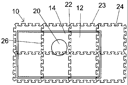
FIG. 1 is a top plan view of a modular shower pan in the process of being
fabricated
at a fabrication facility.
FIG. 2 is a top plan view of a modular shower pan prior to shipping showing
topographical drainage detail.
FIG. 3 is a top plan view of an installed modular shower pan.
FIG. 4 is a side plan view in section of the installed modular shower pan.
FIG. 5 is a perspective view of an individual panel.
FIG. 6 is a detailed top plan view of a glue channel.
FIG. 7 is a top plan view of an individual panel.
FIG. 8 is a detailed top plan view of the panel illustrated in FIG. 7.

CA 02553168 2006-07-19
2
DETAILED DESCRIPTION
A modular shower pan generally identified by reference numeral 10, will now be
described with reference to FIG. 1 through 8.
Structure and Relationship of Parts:
Referring to FIG. 1-3, a modular shower pan 10 comprises square panels 12
(although other polygon shapes could be used) that interlock in side by side
relation to form a
body 14. As shown in FIG. 4, each panel 12 has a planar bottom surface 16 and
a top surface
18 that is sloped based upon a pre-selected drain position 20 on body 14. Each
panel 12 has
an interlocking profile 22 made up of a plurality of interlocking bulbous
projections (keys) 23
and recesses (locks) 24 along each side 26, as detailed in FIG. 5. As shown in
FIG. 8, there
are glue channels 28 in each interlocking bulbous projection 22 and recess 24
that extend
between top surface 18 and bottom surface 16 of each panel 12 to facilitate
securing side
edges 26 of panels 12. Referring to FIG. 6, each glue channel 28 is made up of
a semi-circle
30 that lines up with a corresponding semi-circle 32 on an adjacent panel 12
to form glue
channel 28. On the inside surface of each glue channel 28, there are ribs 34
that create a
larger bonding surface, and allow for greater bonding strength. Referring to
5, there is also
peripheral scoring 36 on each panel 12 to create a frangible connection which
allows bulbous
projections 22 to be broken off to leave a planar edge free from interlocking
profile 22. As
shown in FIG. 7-8, an octagon pattern 38 covers both sides 16 and 18 of each
panel 12 to
provide a better bond to cement or other adhesives when bottom surface 16 is
installed on a
sub-floor, and when a waterproof membrane is installed on top surface 18.
Operation:
Referring to FIG. 2, the method of installation for modular shower pan 10
begins by
measuring the installation dimensions where shower pan 10 is to be installed.
For a
rectangular shaped shower area 40, this would include the length and width.
While a
rectangular shape has been shown as an example, pans for floors with other
shapes are also
possible. If shower area 40 is a shape that is not rectangular, then the
dimensions would
include the shape and size of floor 40 based on its outer profile 44. The size
of drain 20 and its
relative positioning within shower area 40 are also detennined. The dimensions
are then input
into a computer, and software is used to calculate an appropriate slope 42 for
modular shower

CA 02553168 2006-07-19
3
pan 10 to ensure proper drainage to drain 20. Referring to FIG. 1, body 14 of
panels 12 are
temporarily interlocked. The dimensions of body 14 include enough panels 12 to
completely
cover the dimensions of shower floor 40 (generally four or more). Referring to
FIG. 2, a
machine then mills slope 42 onto top surface 18 of body 14 to ensure proper
drainage to drain
20. A score line 46 indicating required drain position 20 is milled into top
surface 18 of body
14. An edge 43 demarking outer profile 44 of shower area 40 is then trimmed,
so that shower
pan 10 is shipped in the form illustrated in FIG. 3. At a job site, an
installer removes panels
12 from their shipping container and assembles panels 12 to reform body 14 by
interlocking
bulbous projections 22 of one panel with recesses 24 of an adjoining panel. As
each panel 12
is installed, it is glued with adhesive to floor area 40, with octagon pattern
38, illustrated in
FIG. 5, assisting with such adhesion. In addition, a glue, such as thinset, is
used along
interlock 22. Referring to FIG. 6, glue channels 28 secures interlock 22
against separation.
A waterproof membrane is then installed over top surface 18 to create a water
seal.
In some installations, the entire floor area must be raised. In such
instances, additional
individual panels are shipped which are used to raise the floor. Referring to
FIG. 5, during
installation, individual panels are trimmed in situ by the installer who
breaks off bulbous
projections 22 along peripheral scoring 36 on each panel 12 to leave a planar
edge free from
interlocking profile 22 for positioning along a wall.
Modular shower pan 10, as described in this patent document, is designed to be
used
with existing shower systems, such as the Schluter Shower System and all its
components. It
is not limited to standard sizes, as each installation is a custom
installation to a particular
shape and drain position. When used, modular shower pan 10 eliminates the need
for the
extensive heavy labour required to install traditional mortar shower pans.
After the
dimensions of shower floor 40 are taken and the milling of each panel 12 is
completed, panels
12 are boxed and brought to shower area 40 to be installed. Because of their
light weight and
interlocking design, modular shower pan 10 can be rapidly installed, usually
in less than 20
minutes, as opposed to five to seven hours with mortar pans. An additional
advantage of this
system over traditional mortar shower pans includes the fact that there is no
need to pre-slope
shower floor 40, and no need for a plumber to be present during installation.

CA 02553168 2006-07-19
4
In this patent document, the word "comprising" is used in its non-limiting
sense to
mean that items following the word are included, but items not specifically
mentioned are not
excluded. A reference to an element by the indefinite article "a" does not
exclude the
possibility that more than one of the element is present, unless the context
clearly requires that
there be one and only one of the elements.
It will be apparent to one skilled in the art that modifications may be made
to the
illustrated embodiment without departing from the spirit and scope of the
invention as
hereinafter defined in the Claims.

Representative Drawing
A single figure which represents the drawing illustrating the invention.
Administrative Status

2024-08-01:As part of the Next Generation Patents (NGP) transition, the Canadian Patents Database (CPD) now contains a more detailed Event History, which replicates the Event Log of our new back-office solution.

Please note that "Inactive:" events refers to events no longer in use in our new back-office solution.

For a clearer understanding of the status of the application/patent presented on this page, the site Disclaimer , as well as the definitions for Patent , Event History , Maintenance Fee  and Payment History  should be consulted.

Event History

Description Date
Maintenance Fee Payment Determined Compliant 2024-07-18
Maintenance Request Received 2024-07-18
Appointment of Agent Request 2022-04-29
Revocation of Agent Request 2022-04-29
Appointment of Agent Request 2022-01-12
Revocation of Agent Requirements Determined Compliant 2022-01-12
Appointment of Agent Requirements Determined Compliant 2022-01-12
Revocation of Agent Request 2022-01-12
Inactive: COVID 19 - Deadline extended 2020-07-16
Common Representative Appointed 2019-10-30
Revocation of Agent Requirements Determined Compliant 2015-05-04
Inactive: Office letter 2015-05-04
Appointment of Agent Requirements Determined Compliant 2015-05-04
Revocation of Agent Request 2015-03-20
Appointment of Agent Request 2015-03-20
Revocation of Agent Requirements Determined Compliant 2011-04-28
Inactive: Office letter 2011-04-28
Appointment of Agent Requirements Determined Compliant 2011-04-28
Grant by Issuance 2011-01-04
Inactive: Cover page published 2011-01-03
Pre-grant 2010-09-21
Inactive: Final fee received 2010-09-21
Letter Sent 2010-07-26
Notice of Allowance is Issued 2010-07-26
Inactive: Approved for allowance (AFA) 2010-06-30
Amendment Received - Voluntary Amendment 2010-05-25
Inactive: S.30(2) Rules - Examiner requisition 2009-11-26
Inactive: Office letter 2008-10-07
Inactive: Delete abandonment 2008-10-07
Deemed Abandoned - Failure to Respond to Maintenance Fee Notice 2008-07-21
Letter Sent 2008-05-15
Request for Examination Received 2008-05-01
Request for Examination Requirements Determined Compliant 2008-05-01
All Requirements for Examination Determined Compliant 2008-05-01
Small Entity Declaration Determined Compliant 2008-05-01
Small Entity Declaration Request Received 2008-05-01
Application Published (Open to Public Inspection) 2008-01-19
Inactive: Cover page published 2008-01-18
Inactive: Adhoc Request Documented 2008-01-02
Revocation of Agent Request 2007-11-16
Appointment of Agent Request 2007-11-16
Inactive: First IPC assigned 2007-04-26
Inactive: IPC assigned 2007-04-26
Inactive: Filing certificate - No RFE (English) 2006-08-22
Application Received - Regular National 2006-08-22

Abandonment History

Abandonment Date Reason Reinstatement Date
2008-07-21

Maintenance Fee

The last payment was received on 2010-05-04

Note : If the full payment has not been received on or before the date indicated, a further fee may be required which may be one of the following

  • the reinstatement fee;
  • the late payment fee; or
  • additional fee to reverse deemed expiry.

Patent fees are adjusted on the 1st of January every year. The amounts above are the current amounts if received by December 31 of the current year.
Please refer to the CIPO Patent Fees web page to see all current fee amounts.

Fee History

Fee Type Anniversary Year Due Date Paid Date
Application fee - small 2006-07-19
Request for examination - small 2008-05-01
MF (application, 2nd anniv.) - small 02 2008-07-21 2008-05-01
MF (application, 3rd anniv.) - small 03 2009-07-20 2009-04-27
MF (application, 4th anniv.) - small 04 2010-07-19 2010-05-04
Final fee - small 2010-09-21
MF (patent, 5th anniv.) - small 2011-07-19 2011-05-17
MF (patent, 6th anniv.) - small 2012-07-19 2012-05-08
MF (patent, 7th anniv.) - small 2013-07-19 2013-05-06
MF (patent, 8th anniv.) - small 2014-07-21 2014-05-05
MF (patent, 9th anniv.) - small 2015-07-20 2015-06-19
MF (patent, 10th anniv.) - small 2016-07-19 2016-07-15
MF (patent, 11th anniv.) - small 2017-07-19 2017-07-19
MF (patent, 12th anniv.) - small 2018-07-19 2018-07-16
MF (patent, 13th anniv.) - small 2019-07-19 2019-07-17
MF (patent, 14th anniv.) - small 2020-07-20 2020-07-17
MF (patent, 15th anniv.) - small 2021-07-19 2021-06-15
MF (patent, 16th anniv.) - small 2022-07-19 2022-04-27
MF (patent, 17th anniv.) - small 2023-07-19 2023-07-07
MF (patent, 18th anniv.) - small 2024-07-19 2024-07-18
Owners on Record

Note: Records showing the ownership history in alphabetical order.

Current Owners on Record
MADISON DANIELS
Past Owners on Record
None
Past Owners that do not appear in the "Owners on Record" listing will appear in other documentation within the application.
Documents

To view selected files, please enter reCAPTCHA code :


To view images, click a link in the Document Description column. To download the documents, select one or more checkboxes in the first column and then click the "Download Selected in PDF format (Zip Archive)" or the "Download Selected as Single PDF" button.

List of published and non-published patent-specific documents on the CPD .

If you have any difficulty accessing content, you can call the Client Service Centre at 1-866-997-1936 or send them an e-mail at CIPO Client Service Centre.


Document
Description 
Date
(yyyy-mm-dd) 
Number of pages   Size of Image (KB) 
Description 2006-07-18 4 155
Abstract 2006-07-18 1 7
Drawings 2006-07-18 8 177
Claims 2006-07-18 2 69
Representative drawing 2007-12-26 1 10
Claims 2010-05-24 3 91
Representative drawing 2010-12-14 1 11
Confirmation of electronic submission 2024-07-17 1 60
Filing Certificate (English) 2006-08-21 1 158
Reminder of maintenance fee due 2008-03-19 1 113
Acknowledgement of Request for Examination 2008-05-14 1 189
Commissioner's Notice - Application Found Allowable 2010-07-25 1 164
Maintenance fee payment 2023-07-06 1 24
Correspondence 2006-08-21 1 63
Correspondence 2007-11-15 5 123
Correspondence 2008-03-19 1 38
Fees 2008-04-30 2 73
Correspondence 2008-04-30 2 73
Correspondence 2008-05-14 1 87
Correspondence 2008-09-14 1 92
Correspondence 2008-10-06 1 15
Fees 2008-09-22 6 152
Fees 2009-04-26 1 31
Correspondence 2010-09-20 1 29
Correspondence 2011-03-30 3 154
Correspondence 2011-04-27 1 12
Correspondence 2011-04-27 1 19
Correspondence 2015-03-19 2 61
Correspondence 2015-05-03 1 21
Correspondence 2015-05-03 1 24
Fees 2015-06-18 1 25
Fees 2016-07-14 1 25
Maintenance fee payment 2017-07-18 1 25
Maintenance fee payment 2018-07-15 1 25
Maintenance fee payment 2019-07-16 1 25
Maintenance fee payment 2020-07-16 1 26
Maintenance fee payment 2021-06-14 1 26
Maintenance fee payment 2022-04-26 1 24