Note: Descriptions are shown in the official language in which they were submitted.
CA 02554043 2006-07-19
WO 2005/076729 PCT/IL2005/000163
ACOUSTIC CONTROL OF EMBOLI IN VIVO
CROSS-REFERENCE TO RELATE APPLICATIONS
This application claims the benefit of U.S. Provisional Patent Application
60/544,459,
filed Febmary 12, 2004, and of U.S. Provisional Patent Application 60/572,283,
filed May 17,
2004. This application is a continuation-in-part of U.S. Patent Application
10/162,824, filed
June 4, 2002, and published as Patent Application Publication US 2003/0221561
Al. The
disclosures of all these related applications are incorporated herein by
reference.
FIELD OF THE INVENTION
The present invention relates generally to invasive medical devices and
procedures, and
specifically to devices and methods for controlling embolic flow in the
bloodstream.
BACKGROUND OF THE INVENTION
It is known in the art that acoustic waves traveling through a liquid exert a
force on
particles and bubbles suspended in liquid. The nature and strength of the
interaction between
acoustic waves and such particles is described, for example, by Yosiolca acid
I~awasima, in
"Acoustic Radiation Pressure on a Compressible Sphere," Acustica 5 (1955),
pages 167-173,
which is incorporated herein by reference. This paper provides analytical
formulas for
calculating the acoustic force based on the parameters of the acoustic wave,
the particles and
the ambient liquid.
The above-mentioned Patent Application Publication US 2003/0221561 A1
describes
ultrasonic devices that male use of acoustic radiation pressure in preventing
emboli from
reaching the brain dining invasive cardiological procedures, such as
cardiovascular surgery.
(The term "embolus," as used in the context of the present patent application
and in the claims,
refers to any abnormal particle circulating in the blood. Such particles may
include, ifatey- alicz,
cholesterol, platelet clumps, blood clots, calcium flecks, air bubbles, fat,
and combinations of
these components.) The published patent application describes various
different devices for
this pwpose, including invasive devices that are designed for placement in the
chest cavity
d111111g surgery and operate in combination with needle vents or other vent
systems for
removing diverted microbubbles.
In one embodiment described in US 2003/0221561 A1, a device for removing
emboli
from the bloodstream comprises a transducer associated with the exterior
surface of the
1
CA 02554043 2006-07-19
WO 2005/076729 PCT/IL2005/000163
posterior side of the aorta in the general region of the transverse sinus. The
transducer is
powered to generate ultrasonic waves that axe directed toward the anterior
side of the aorta. A
needle vent is inserted into the anterior side of the aorta downstream of the
transverse sinus, so
that emboli diverted by the transducer are removed through the needle vent.
SUMMARY OF THE INVENTION
Embodiments of the present invention provide improved devices and methods for
diversion of embolic flow within a blood vessel by transmitting ultrasonic
waves into the
vessel. These embodiments avoid the necessity of puncturing or otherwise
invading the
interior of the blood vessel, as is required in other methods that are known
in the art.
The devices described hereinbelow are adapted particularly for deployment in
the chest
cavity, so as divert emboli flowing in the aortic arch into the descending
aorta and away from
the great origins of the neck vessels leading to the brain. Because the device
is placed in close
proximity to the target vessels, it can be aligned quickly and accurately by
simple means. Such
devices are useful particularly in preventing neurological damage that may
occur due to release
of emboli during cardiac surgery and other invasive cardiological procedures.
The principles
of the present invention may also be applied, however, for diversion of blood
flow in other
locations, such as the carotid bifurcations.
There is therefore provided, in accordance with an embodiment of the present
invention, a device for controlling a flow of emboli in aa.1 aorta of a
patient, the device
including:
an ultrasonic transducer, which is configured to transmit an ultrasonic beam
into the
aorta in a vicinity of a great origin of a neck vessel; and
a driver circuit, which is coupled to drive the ultrasonic transducer to
generate the
ultrasonic beam at a frequency and power level sufficient to divert at least a
target fraction of
the emboli of a given type and size away from the neck vessel.
In a disclosed embodiment, the driver circuit is coupled to drive the
ultrasonic
transducer so as to reduce the flow of the emboli of the given size and type
into the neck vessel
by at least 80°~0, and the ultrasonic transducer is configured to
transmit the ultrasonic beam so
as to divert at least the target fraction of the emboli into the descending
aorta.
hi some embodiments, the device includes a holder, which is coupled to hold
the
ultrasonic transducer in proximity to the aorta. The holder may be fixed to a
retractor, which is
2
CA 02554043 2006-07-19
WO 2005/076729 PCT/IL2005/000163
used to spread a sternum of the patient during open heart surgery. Typically,
the holder is
configured to hold the ultrasonic transducer on an anterior side of the aorta,
so that the
ultrasonic transducer transmits the ultrasonic beam in a posterior direction
through the aorta.
W some embodiments, the ultrasonic beam is unfocused. W one embodiment, the
ultrasonic beam has an intensity in the aorta of at least 0.3 W/cmz, and the
ultrasonic beam
diverges from the transducer through the aorta.
Typically, the device includes a flexible coupler interposed between the
transducer and
the aorta. In some embodiments, the flexible coupler includes at least one of
a gel and a
polyner. In other embodiments, the flexible coupler includes a membrane, which
contains a
fluid for coupling the ultrasonic beam from the transducer to the aorta. W one
of these
embodiments, the device includes a housing, which contains the transducer and
the fluid,
wherein the membrane forms at least part of the housing, the housing including
a fluid port for
injecting the fluid into the housing while the transducer is fixed in
proximity to the aorta. The
device also includes a fluid circulation assembly coupled to the fluid port so
as to cool the
transducer by passage of the fluid through the housing, wherein the fluid
circulation assembly
includes a closed circuit.
In another embodiment, the device includes an acoustic waveguide, which is
adapted to
convey the ultrasonic beam from the ultrasonic transducer to the aorta. The
acoustic
waveguide has a distal end, which is configured to be brought into proximity
with the aorta,
and may include a diverging optic in a vicinity of the distal end.
W some embodiments, the driver circuit is adapted to actuate the ultrasonic
transducer
intermittently, responsively to variations in the flow of the emboli into the
aorta. Iii one
embodiment, the driver circuit is coupled to receive an indication of a
heartbeat of the patient,
and to actuate the ultrasonic transducer in synchronization with the
heartbeat. W another
embodiment, the driver circuit is adapted to actuate the ultrasonic transducer
at a low power
level during a first time period and at a high power level during a second
time period,
responsively to a variation in the flow of the emboli into the aorta
associated with the second
time period.
In further embodiments, the driver circuit is operative to actuate the
ultrasonic
transducer with pulsed excitation.
There is also provided, in accordance with an embodiment of the present
invention, a
device for controlling a flow of emboli in an aorta of a patient, the device
including:
3
CA 02554043 2006-07-19
WO 2005/076729 PCT/IL2005/000163
an ultrasonic transducer, which is configured to transmit an ultrasonic beam;
and
a holder, including a proximal end that is adapted to be fixed to a retractor
used to
spread a sternum of the patient during open heart surgery, and a distal end
that is coupled to
hold the ultrasonic transducer in proximity to the aorta so that the
transducer transmits the
ultrasonic beam into the aorta during the surgery.
There is additionally provided, in accordance with an embodiment of the
present
invention, a device for conveying acoustical energy into tissue having an
irregular shape, the
device including:
an ultrasonic transducer, which is configured to tranS1111t an ultrasonic
beam; and
a flexible coupler interposed between the transducer and the tissue, the
coupler
including a matching material having acoustical properties similar to those of
the tissue, which
is adapted to deform to fit the irregular shape of the tissue so that the
ultrasonic beam passes
through the matching material into the tissue.
There is further provided, in accordance with an embodiment of the present
invention,
an ultrasonic assembly, including:
an ultrasonic transducer, which is configured to transmit an ultrasonic beam;
a housing, which contains the ultrasonic transducer and includes a coupler for
coupling
the ulhasonic beam into a target tissue;
cabling, having distal and proximal ends, the distal end coupled to the
housing and
including an electrical cable and fluid tubing; and
a cassette coupled to the proximal end of the cabling, the cassette including:
an electrical connector coupled to the electrical cable and adapted to be
coupled
to a power source for driving the transducer; and
a fluid reservoir coupled to the fluid tubing and containing a fluid for
circulation through the housing via the tubing in order to cool the
transducer.
h1 a disclosed embodiment, the assembly includes a console having a receptacle
sized
to receive the cassette, the console containing the power source for engaging
the electrical
comiector and a mechanical drive for driving the circulation of the fluid.
Typically, the
console is adapted to drive the circulation of the fluid without contacting
the fluid, which
flows in a closed circuit through the tubing. Additionally or alternatively,
the console may
include a cooling device, which is positioned to thermally engage the fluid
reservoir when the
cassette is inserted in the receptacle. Further additionally or alternatively,
the cassette includes
4
CA 02554043 2006-07-19
WO 2005/076729 PCT/IL2005/000163
an electronic device containing data regarding the assembly, and the console
includes a
wireless reader, which is coupled to read the data from the electronic device
when the cassette
is inserted in the receptacle. In one embodiment, the fluid reservoir and W
bing are filled with
the fluid and then hermetically sealed and sterilized before use of the
assembly.
There is moreover provided, in accordance with an embodiment of the present
invention, a lnethod for controlling a flow of emboli in an aorta of a
patient, the method
including transmitting an ultrasonic beam into the aorta in a vicinity of a
great origin of a neck
vessel with an ultrasonic frequency and power level sufficient to divert at
least a target fraction
of the emboli of a given type and size away from the neclc vessel.
In a disclosed embodiment, transmitting the ultrasonic beam includes actuating
the
ultrasonic beam intermittently, responsively to variations in the flow of the
emboli into the
aorta. Typically, actuating the ultrasonic beam includes receiving an
indication of a heautbeat
of the patient, and actuating the ultrasonic beam in synchronization with the
heartbeat.
There is furthermore provided, in accordance with an embodiment of the present
invention, a method for conveying acoustical energy into tissue having an
irregular shape, the
method including:
interposing a flexible coupler between an ultrasonic transducer and the
tissue, the
coupler including a matching material having acoustical properties similar to
those of the
tissue, which is adapted to deforn to fit the irregular shape of the tissue;
and
transmitting an ultrasonic beam from the ultrasonic transducer through the
matching
material into the tissue.
The present invention will be more fully understood from the following
detailed
description of the embodiments thereof, taken together with the drawings in
which:
BRIEF DESCRIPTION OF THE DRAWINGS
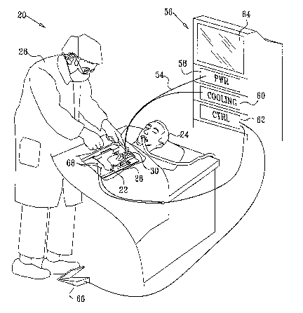
Fig. 1 is a schematic, pictorial illustration of a system for diversion of
emboli during a
cardiac surgical procedure, in accordance with an embodiment of the present
invention;
Fig. 2 is a schematic frontal view of the chest cavity of a patient during
cardiac surgery,
showing placement of an ultrasonic device for diversion of emboli, in
accordance with an
embodiment of the present invention;
5
CA 02554043 2006-07-19
WO 2005/076729 PCT/IL2005/000163
Fig. 3 is a schematic side view of the chest cavity taken along a line III-III
in Fig. 2,
showing details of the placement of the ultrasonic device adjacent to the
aorta, in accordance
with an embodiment of the present invention;
Fig. 4 is a schematic, cross-sectional view taken along a line IV-IV in Fig.
3,
illustrating acoustical coupling between the ultrasonic device and the aorta,
in accordance with
an embodiment of the present invention;
Figs. 5A and SB are schematic side and rear views of a cooled ultrasonic
device for
diversion of emboli, in accordance with an embodiment of the present
invention;
Fig. 6A is a schematic side view of an assembly for ultrasonic diversion of
emboli, in
accordance with another embodiment of the present invention;
Fig. 6B is a schematic end view of the assembly of Fig. 6A, showing details of
a
connection between the assembly and a control console, in accordance with an
embodiment of
the present invention;
Fig. 7 is a schematic, pictorial illustration of an ultrasonic device for
diversion of
emboli during a cardiac surgical procedure, using a waveguide for transmission
of acoustic
energy, in accordance with an embodiment of the present invention; and
Fig. 8 is a schematic side view of an acoustic waveguide used in the device of
Fig. 7, in
accordance with an embodiment of the present invention.
DETAILED DESCRIPTION OF EMBODIMENTS
Fig. 1 is a schematic, pictorial illustration of a system 20 for diversion of
emboli during
an invasive procedure performed on a heart 22 of a patient 24, in accordance
with a.n
embodiment of the present invention. W this example, a surgeon 26 has opened
the patient's
chest by performing a medical sternotomy, and has then attached a retractor 28
to spread the
two parts of the sternum. The surgeon then cuts through the pericardium to
expose the heart,
as is known in the art. Before proceeding with the actual procedure on the
heaz-t, the surgeon
places next to the aorta, in the most cranial part of the incision, an
ultrasonic device 30 for
diversion of emboli. Device 30 is deployed aazd operated to direct an
ultrasonic beam into the
aorta in such a way as to divert emboli in the aorta away from the great
origins of the neck
vessels. The structural and functional characteristics of device 30 are shown
in detail in the
figures that follow.
Fig. 2 is a schematic frontal view of a chest cavity 32 of patient 24, in
accordance with
an embodiment of the present invention. The clamps of retractor 28 hold the
sternum open,
6
CA 02554043 2006-07-19
WO 2005/076729 PCT/IL2005/000163
and pericarditun 34 is cut away to expose heart 22. Device 30 is placed
against aorta 36, in
proximity to the great origins of neck vessels 38, which include the
innominate artery, the left
common carotid artery and the left subclavian artery. (Superior vena cava 40
is shown for
completeness.) In this embodiment, device 30 is held in place by an
articulating arm 42, which
is fastened to one of the clamps of retractor 28. Device 30 is thus held
stably in the desired
location and orientation in the upper chest cavity without interfering with
the surgical field.
Additionally or alternatively, other means may be used to hold device 30 in
place. For
example, malleable wires attached to the device housing may be wrapped arotmd
the aorta and
then sutured to prevent movement during the procedure.
Fig. 3 is a schematic side view of chest cavity 32 taken along a line III-III
in Fig. 2.
This figure illustrates further features of the mounting and operation of
device 30, in
accordance with an embodiment of the present invention. Note that device 30 is
partly hidden
beneath the patient's slcin at the upper side of the open chest cavity (to the
left in Fig. 3),
although the entire device is revealed in Fig. 2 for the sale of visual
clarity.
Device 30 comprises an ultrasonic transducer 44, such as a piezoelectric
element or an
array of such elements. Transducer 44 is coupled to aorta 36 through an
acoustic coupler 46,
in order to provide efficient energy transfer from the transducer to the blood
vessel. Coupler
46 typically comprises a matching layer, i.e., a material that is acoustically
transparent and
possesses acoustical properties similar to those of soft tissue. For example,
the material in
coupler 46 may comprise an ultrasonic gel, silicone, polyethylene or even
water (which may
circulate to cool the transducer, as described below with reference to Fig.
5). As shown in Fig.
3, coupler 46 is sufficiently flexible to deform in order to fit the irregular
shape of the tissue
with which it is in contact. This deformation provides continuous coupling
between device 30
and aorta 36, thus enhancing the efficiency of ultrasonic energy delivery.
In an alternative embodiment, not shoran in the figures, the acoustic coupler
of device
has a concave surface, which creates a closed cavity when the device is
pressed against the
target tissue. The cavity is then evacuated through a vacuum port in the
device, causing the
concave surface to flatten and adhere firmly to the tissue. The coupler is
made flexible enough
so that only a weak vacuum is necessary to achieve this effect. The vacuum is
vented at the
30 end of the procedure to permit the device to be removed.
Fig. 3 also shows the trajectory of a stream of emboli 48 emitted through
aortic valve
50 (or possibly detached from the ascending aorta) into aorta 36. Actions of
surgeon 26 during
7
CA 02554043 2006-07-19
WO 2005/076729 PCT/IL2005/000163
cardiac surgery, such as cannulation, de-cannulation and cross-clamping, are
particularly Iilcely
to cause such emboli to be released into the bloodstream. In the absence of
device 30, some of
these emboli would simply be entrained in the branching blood flow into neclc
vessels 38.
Device 30, however, is aimed so that the acoustic beam generated by transducer
44 exerts
pressure on emboli 48 toward the descending aorta and away from the great
origins of vessels
38. Thus, the emboli are diverted away from the neck vessels, and the brain of
patient 24 is
protected from neurological damage that could result if emboli 48 were to pass
through one of
vessels 38 and lodge in smaller blood vessels in the brain. Although the
inventors have found
the location and orientation shown in Fig. 3 to be optimal for diverting
emboli into the
descending aorta, other configurations can also be effective and are
considered to be within the
scope of the present invention. For example, ultrasonic transducers may be
positioned at other
locations and orientations along aorta 36 or in proximity to other blood
vessels, in addition or
alternatively to the location and orientation shown in Fig. 3.
Fig. 4 is a schematic, cross-sectional view of device 30 and aorta 36, talcen
along a line
IV-IV in Fig. 3. This figure shows a diverging acoustic beam 52 generated by
transducer 44,
in accordance with an embodiment of the present invention. The beam is
directed toward the
posterior part of the body (as illustrated in the preceding figures) and is
wide enough to extend
over at least the orifices of the first two branches of neck vessels 38, i.e.,
the imlominate artery
and the left common carotid artery. Typically, the width of beam 52 at this
point is about 1 cm
or more, and the average beam intensity is at least 0.3 W/cmZ at a frequency
of about 0.5 MHz
or more.
The inventors found in bench and animal experiments ifz vivo that beam
parameters of
frequency 2.2 MHz and average intensity of 2 W/cm' were sufficient to divert
at least 80% of a
stream of polystyrene test particles 0.5 mm in diameter. In other words, under
these beam
conditions, the number of emboli of size 0.5 mm that enter the necl~ vessels
is reduced by at
least 80% relative to the number that would enter the necl~ vessels in the
absence of device 30.
A much lower intensity, as low as 0.5 W/cmz was sufficient to divert the vast
majority of air
bubbles.
Alternatively, other beam parameters may be used to divert a given target
fraction of
the particles of any other given size and type. In the context of the present
patent application
and in the claims, the "target fraction" refers to the percentage of the
embolic pauticles that are
to be diverted away from the neck vessels. The probability of neurological
damage is reduced
8
CA 02554043 2006-07-19
WO 2005/076729 PCT/IL2005/000163
accordingly. The greater the beam intensity, the higher will be the percentage
of emboli
diverted. The higher the frequency, the smaller v~rill be the minimtun size of
embolic particles
that can be effectively diverted by the ultrasonic beam of device 30. For
example, an
ultrasonic beam with a frequency of 3 MHz is effective in diverting emboli
whose size is 200
~,m, while higher frequencies may be effective in diverting emboli as small as
100 Vim. Higher
frequencies, however, tend to have a stronger heating effect on the aorta and
surrounding
tissues. The optimal choice of ultrasound frequency and beam power will be
apparent to those
skilled in the art based on the criteria outlined herein. Ultrasound imaging
of the blood vessels
may be used to ascertain the effectiveness of a given frequency and beam power
in diverting
emboli of any given target size.
The use of diverging beam 52 is advantageous both in covering the entire cross-
section
of aorta 36 using a relatively small transducer, and in avoiding thermal
damage to underlying
tissues, such as the lungs and veutebrae. For example, asstuning that the
diameter of beam 52
at the vertebrae is twice the diameter in the aorta, the acoustic intensity at
the vertebrae will
then be only 25% of the intensity in the aorta. (The intensity generated at
transducer 44, on the
other hand, should be higher than the desired intensity in the aorta by a
factor sufficient to
compensate for the beam divergence.) To generate the diverging beam,
transducer 44 may
comprise a convex piezoelectric element or an array of piezoelectric elements
mounted on a
convex surface. Alternatively, the transducer may comprise a phased array of
elements, which
are driven electronically to generate the diverging beam. Any suitable
diverging beam shape
may be generated, using these or other transducer configurations known in the
art.
In an alternative embodiment, not shown in the figures, transducer 44
generates a
focused ultrasonic beam, which is aimed toward the great origins of neck
vessels 38 in aorta
36 so as to deflect emboli 48 away from these specific locations. This
approach is
advantageous in reducing the total amount of ultrasonic energy to which the
aorta is exposed,
but it requires precise aligmnent of device 30. To aid in this alignment,
device may comprise a
Doppler ultrasound transducer, which detects the locations of the origins of
the neck vessels
based on the Doppler signature of the associated blood flow. The Doppler
transducer may be
mounted, for example, at the center of the power transducer that is used to
generate the
diverting beam. The power transducer is then aimed, either manually or
automatically, so as to
focus at the location indicated by the Doppler signal.
9
CA 02554043 2006-07-19
WO 2005/076729 PCT/IL2005/000163
In still another embodiment, transducer 44 generates a non-focused ultrasound
beam,
whose diameter is roughly equal to or greater than the diameter of aorta 36.
Sllch a beam may
be generated, for example, by a piston-shaped transducer having a flat active
element. In the
context of the present patent application and in the claims, acoustic beams
that are non-focused
or substantially divergent within the aorta are referred to collectively as
"unfocused beams."
Returning now to Fig. 1, it can be seen that device 30 is connected by cabling
54 to a
console 56. The console comprises a power driver circuit 58, which generates
radio frequency
(RF) energy for driving device 30, typically at the appropriate optimal
frequency for transducer
44. Typically, the frequency generated by circuit 58 is in the range of 0.5
MHz or higher, with
an electrical power output of at least 5 W for an unfocused beam. (The power
level may be
lower in embodiments that use a focused beam.) Alternatively, higher or lower
frequencies and
power levels may also be used, in accordance with therapeutic needs and
technical constraints.
As noted earlier, the frequency and power level are typically chosen by
balancing the target
particle size and the desired diversion percentage against the possible side
effects of excessive
tissue heating.
Cabling 54 may optionally comprise tubing for circulation of fluid between
device 30
and a cooling unit 60. The purpose of the fluid circulation is to avoid
overheating of
transducer 44 during operation and to cool tissues with which acoustic coupler
46 is in contact.
If the fluid circulates through coupler 46, the fluid can also serve as an
effective coupling
meditun between the ultrasonic transducer and the tissue. These features of
system 20 are
described further hereinbelow with reference to Figs. 5A, SB, 6A and 6B.
The operation of system 20 is controlled by a control unit 62, which typically
comprises a microprocessor with suitable interface and logic circtuts for
interacting with the
other components of the system. Typically, the control unit activates and de-
activates driver
circuit 58 a.nd cooling trait 60, based on parameters that are input to the
system via a user
interface 64. The user interface may comprise a touch screen, keyboard and/or
pointing device
(not shown). A remote control 66, such as a foot pedal, may also be provided
to enable
surgeon 26 (or another user) to switch device 30 on and off during surgery.
W order to reduce tissue heating, it is desirable that device 30 be controlled
to emit an
acoustic beam only when required, rather than operating continuously
throughout the surgical
procedure. In order to control device 30 in this mamler, control unit 62 may
be programmed to
permit a number of different modes of operation, for example:
CA 02554043 2006-07-19
WO 2005/076729 PCT/IL2005/000163
~ Continuous mode, in which operation of device 30 is controlled directly by
sl~rgeon 26 (or
by another operator), typically using remote control 66. It is expected that
the surgeon will
actuate driver circuit 58 during surgical activities that are associated with
high rates of
embolism, such as cannulation, de-caimulation and cross-clamping.
~ Intermittent mode, for use particularly at acoustical power levels that are
too high for
continuous operation. In this case, the surgeon (or other operator) actuates
driver circuit 58
just before beginning an activity that is likely to cause release of emboli.
Control unit 62
permits the driver circuit to run for a predetermined length of time,
typically between a few
seconds and twenty minutes, depending on the acoustic beam frequency and
power. At the
end of the permitted time period, the control unit shuts the driver circuit
off and prevents
fiu-ther operation of device 30 until a certain lockout period has elapsed.
~ Multi-power mode, for use in procedures in which air emboli are created
throughout most
of the duration of the procedure (emanating from a heart-lung machine, for
example), and
solid emboli are created in a short duration following aortic manipulations.
For energy
efficiency, the acoustic beam is active at low intensity for most or all of
the procedure to
divert the air bubbles. During aortic manipulations, the system is
intermittently switched to
high intensity for a short period of time (as in the intermittent mode above)
to divert solid
emboli.
~ Synchronized mode, for use in procedures (or parts of procedures) in which
the patient's
heart is beating. Control unit 62 may sense the heartbeat based on ECG signals
from
electrodes 68, for example, or other monitored physiological parameters. The
control unit
actuates device 30 to generate the acoustic beam in synchronization with the
heartbeat so
as to match the cardiac output function. Typically, the control unit turns on
the beam at
full power only during peals systolic flow, while the beam power is reduced
(or even turned
off) during the remainder of the heart cycle, during which the rate of blood
flow tluough
aortic valve 50 is much lower. This mode of operation reduces the average
acoustic power
applied to aouta 36 by a factor of 3-4 relative to the continuous mode.
W all of the above modes, when device 30 is actuated, it may be driven by
either
continuous wave (CW) or pulsed excitation, i.e., with a duty cycle less than
100%. When
pulsed excitation is used, the radiation pressL~re exerted on the emboli is
pulsed. The emboli
can thus accumulate diversion by virtue of momentum acquired during previous
pulses,
11
CA 02554043 2006-07-19
WO 2005/076729 PCT/IL2005/000163
resulting in more efficient diversion at lower average acoustic power as
compared with
continuous excitation. Another advantage of pulsed excitation is that it
broadens the spectral
band of the emitted acoustic wave, resulting in a more homogeneous beam in the
near field
zone..
As noted above, cooling unit 60 is optional, and the need for such a unit
depends on the
configuration of device 30 and on the efficiency and mode of operation of
transducer 44.
Refernng, for example, to the configuration shown in Fig. 4, let us asslune
that transducer 44
generates 40 W of acoustic power with an efficiency of 80%, meaning that the
transducer
generates 10 W of heat. Assuming coupler 46 to comprise a gel pad of volume 40
cm3, the
heat generated by transducer 44 will cause the temperature of the gel pad to
increase by about
3.5°C per minute of operation. Thus, as long as actuation of device 30
is limited to periods of
no more than a few minutes, separated by inactive periods of at least equal
length to permit the
gel pad to cool, device 30 may operate without external cooling. When high
enough acoustic
power is applied so that passive temperature dissipation is insufficient, or
transducer 44 is less
efficient, an external cooling circuit may be used, such as those described
below.
Figs. 5A and SB schematically illustrate a fluid-cooled ultrasonic device 70
for
diversion of emboli, in accordance with an embodiment of the present
invention. Fig. 5A
shows a side view of device 70, together with elements of console 56, while
Fig. 5B is a rear
view of the device. Device 70 may be used in system 20 in substantially the
same manner as
device 30, and has similar properties to device 30 with the exception of the
specific points
described hereinbelow. In device 70, transducer 44 is contained inside a
housing 72, which is
filled with a circulating fluid supplied by cooling unit 60. The transducer
receives RF power
from circuit 58 via a power feed-tYlrough 74 in a mount 76, which fixes the
transducer to
housing 72. The housing typically comprises a rigid biocompatible plastic,
such as an acrylic,
polycarbonate or fluorocarbon material, polyetheretherketone (PEEK) or a
biocolnpatible
metal, such as stainless steel, titanium or aluminum. The front of the housing
comprises an
acoustic window 80, through which acoustic waves from transducer 44 are
emitted. The
window typically comprises a thin, flexible, acoustically-transparent
membrane, such as latex,
silicone, polyurethane or polyethylene.
Cooling unit 60 pumps fhlld through housing 72 via tubing 78, which is
connected to
an inlet port 82 and an outlet port 84 of the housing. The fluid flows through
the space
between housing 72 and mount 76 into and out of the region between transducer
44 and
12
CA 02554043 2006-07-19
WO 2005/076729 PCT/IL2005/000163
window 80. (The area inside mount 76 may be filled with air.) The fluid in
this case performs
the role of coupler 46 in the preceding embodiment. In other words, the fluid
both cools
transducer 44 and serves as the flexible matching layer between the transducer
and the target
tissues in the body of patient 24. The housing is hermetically sealed except
for ports 82 and
84.
Typically, window 80 is slacl~ until housing 72 is pressurized with the fluid,
which then
presses the window against the adjacent tissues so that the fluid hatching
layer inside the
housing conforms to the target tissues. Outlet pol-t 84 may be narrower than
inlet port 82 in
order to facilitate pressurization of the housing. In an alternative
embodiment, not shown in
the figures, the sides of the transducer housing also comprise thin, flexible
material, life
window 80, so that the housing inflates like a balloon when pressurized with
fluid. Other
materials and methods of construction will be apparent to those spilled in the
al-t.
Cooling unit 60 comprises a pump 86, which circulates the fluid between
housing 72
and a cooling device 88, such as a refrigerator or heat exchanger. The cooling
lullt t11L1S
ensures both that device 70 is kept at the proper temperature and that housing
72 is pressurized
in order to inflate window 80. Rapid flow of fluid through housing 72 also
removes air
bubbles that otherwise might disperse some of the acoustic energy emitted by
transducer 44.
While the combined acoustic matching and cooling functions performed by the
fluid in
housing 72 are particularly useful when device 70 is used for diversion of
elnboli in the aorta,
this sort of transducer assembly and housing can also be used in other medical
ultrasound
applications, particularly applications involving high-power acoustic
sonication.
Other schemes may also be used for cooling transducer 44. For example, cooled
liquid
or gas (or both) may flow through the transducer housing on the baclc side of
the transducer,
while the front side is coupled to the target tissue through a gel or polymer
matching layer. As
another example, the back side of the transducer may be air-cooled, while
cooling fluid flows
over the front of the transducer. Other cooling schemes will be apparent to
those spilled in the
art.
Fig. 6A is a schematic side view of a disposable transducer assembly 90, in
accordance
with another embodiment of the present invention. Assembly 90 comprises an
ultrasonic
device 92, which contains a transducer (as shown in the preceding figures) and
an acoustic
coupler 94, along with arm 42, as described above. The acoustic coupler may
comprise any
suitable material, such as polymer, gel or liquid, either stationary or
flowing, as described
13
CA 02554043 2006-07-19
WO 2005/076729 PCT/IL2005/000163
above. Device 92 is connected by cabling 54 to a cassette 96, which is
designed to be inserted
into and mate with a receptacle in cooling unit 60. Assembly 90 is provided as
an integral,
sealed, sterile unit, intended to be used once and then disposed of
thereafter.
Cabling 54 comprises electrical cable 98, for providing power to the
transducer in
device 92, and fluid hoses 100, through which liquid or gas circulates to and
from device 92 in
order to cool the transducer. Cable 98 terminates in a connector 102 at a
proximal side 104 of
cassette 96. The fluid in hoses 100 is pumped through a cooling reservoir 106
in cassette 96
by a rotor I08. The rotor is driven through a shaft 110, which lilcewise
terminates at the
proximal side of the cassette. Alternatively, a section of hose 100 may
protrude at one of the
sides of the cassette to engage a roller pump in cooling Lmit 60. W either
case, the fluid in
assembly flows in a closed circuit. Cassette 96 may thus be hermetically
sealed (with suitable
feedthroughs for cabling 54, connector 102 and shaft 110), so that the fluid
inside assembly 90
never comes into contact with cooling unit 60, and the sterility of device 92
is maintained.
Fig. 6B is a schematic end view of cassette 96 inside cooling unit 60, seen
from
proximal side 104 of the cassette. Comlector 102 and shaft 110 mate with
suitable electrical
and mechanical drive connectors (not shown) inside the cooling mit when the
cassette is
plugged into the mating receptacle. Although cassette 96 is shown in this
figure to be
rectaxlgular in shape, other shapes of the cassette and the mating receptacle,
such as a
cylindrical shape, are also possible. Reservoir 106 is positioned inside
cassette 96 next to one
of the side walls of the cassette, which comes in contact with a cooling
device 112, such as a
Peltier cooler, lIl unlt 60. The fluid in the reservoir is thus cooled by
transfer of heat tluough
the side wall of the cassette to the cooling device. Optionally, cassette 96
comprises an
electronic identification chip 114, containing information that can be read
Ollt by a wireless
reader 116 in cooling unit 60 in order to verify that assembly 90 is of the
proper type and is
used no more than once.
Fig. 7 is a schematic, pictorial illustration showing an ultrasonic device 120
for
diversion of emboli during a cardiac surgical procedure, in accordance with
yet another
embodiment of the present invention. In this embodiment, a transducer 122 is
remotely
located, away from the surgical site_ Ultrasonic waves are transferred from
the transducer to
the surgical site via an acoustic waveguide 124. This approach alleviates the
need to sterilize
the ultrasonic transducer, and also reduces mechanical and thexmal problems
and constraints
associated with positioning the transducer in the chest cavity.
14
CA 02554043 2006-07-19
WO 2005/076729 PCT/IL2005/000163
Fig. 8 is a schematic side view of waveguide 124, in accordance with an
embodiment
of the present invention. The waveguide comprises a hollow shell 126, made of
a flexible,
non-kinking material such as a thin plastic or metal. The shell is filled with
a coupling
material 128, such as a liquid, gel or polymer, having low acoustic
attenuation and acoustical
properties similar to the target tissue of patient 24. For example, material
128 may comprise
degassed water or acoustic gel. Material 128 may be static or, if the material
is liquid, it may
be circulated through shell 126 by a suitable pump and cooling system (not
shown).
Shell 126 should be substantially thinner than the acoustic wavelength of the
ultrasonic
waves generated by transducer 122 in order to avoid transfer of acoustical
energy from
material 128 to the shell. If material 128 comprises a liquid or gel, the
distal and proximal
ends of waveguide 124 are also closed by respective membranes 130 and 132.
Transducer 122
is coupled to the waveguide through membrane 132, while membrane 130 contacts
the target
tissue in the patient's body and deforms to c~uple with the target tissue.
Optionally, waveguide 124 comprises optics, such as a diverging lens 134, for
generating a diverging output beam, as shown, for example, in Fig. 4. The
shape and
refractive index of lens 134 are chosen so as to engender the desired
divergence angle in the
ultrasonic beam. The material in lens 134 is chosen to have acoustic impedance
close to the
impedance of material 128 in order to minimize back-reflection from the lens.
Alternatively, a
divergent beam may be created at the output of the waveguide by forming the
output side of
the waveguide in a trumpet-life shape (not shown).
Although the ultrasonic devices described hereinabove are designed
specifically for use
in diversion of emboli in the aouta, the principles of these devices may be
applied, nautatis
nazctafzdis, for diversion of emboli in other locations, such as the carotid
bifurcation, as well as
in other invasive and non-invasive applications of medical ultrasound.
Similarly, although
certain specific device designs are shown and described hereinabove, the
therapeutic principles
embodied in these devices may also be implemented using other device designs,
as will be
apparent to those slcilled in the art.
It will thus be appreciated that the embodiments described above are cited by
way of
example, and that the present invention is not limited to what has been
particularly shown and
described hereinabove. Rather, the scope of the present invention includes
both combinations
and subcombinations of the various features described hereinabove, as well as
variations and
CA 02554043 2006-07-19
WO 2005/076729 PCT/IL2005/000163
modifications thereof which would occur to persons skilled in the art upon
reading the
foregoing description and which are not disclosed in the prior art.
1G