Note: Descriptions are shown in the official language in which they were submitted.
CA 02554117 2006-07-20
WO 2005/074089 PCT/FI2005/000066
THERMAL OVERLOAD PROTECTION
BACKGROUND OF THE INVENTION
[0001] The invention relates to thermal overload protection for pro-
tecting electrical devices, and particularly electric motors, from
overheating.
[0002] Electric motors are utilized in several applications for driving
various moving parts. An electric motor often has an associated control unit
for
adjusting and monitoring the operation of the electric motor, the speed of
rota-
tion, for example.
[0003] An electric motor may temporarily operate also overloaded,
but if it becomes overheated as the loading continues, this may result in dam-
age to the motor. Damage to the isolation of the stator coiling caused by over-
heating is the most critical.
[0004] Various solutions are known for protecting an electric motor
against thermal overload. One known solution is based on 1..3-phase meas-
urement of the motor current and on modelling the heating of the motor by us-
ing an RC equivalent circuit. The oldest and most common technical imple-
mentation is a bimetallic relay (thermal relay) coupled directly or via a
current
transformer to the main circuit.
[0005] A known solution is a thermal safety switch arranged inside
or in connection with the motor, the switch tripping after a given temperature
limit and interrupting the current flow through the electric motor. A more ad-
vanced version is an electronic unit that measures the temperature of the elec-
tric motor with temperature sensors and triggers a shut-off of the motor. This
alternative manner is directly based on temperature detection with various
sensors. The problem is the difficulty of placing the sensors correctly. Such
a
protection reacts relatively slowly.
[0006] In numerical protection, data is processed in a numeric for-
mat, i.e. digitally. Analogical measurement data are converted with an A/D
converter into digital. The actual measurement and protection functions are
implemented by means of a microprocessor. The thermal overload protection
measures the root mean square (rms) values of the phase currents (load cur-
rents) of a motor or another object to be protected (e.g. a cable or a trans-
former), and calculates the temperature-dependent operating time. This ther-
mal operating time may be accordant with standard IEC 60255-8:
I~- I ~
P
f= ?In -
li. 1b2
CA 02554117 2006-07-20
WO 2005/074089 PCT/FI2005/000066
2
wherein
t = operating time
~ = time constant
Ip = load current before overload ..
I = load current
Ib = operating current (maximum allowed continuous current)
[0007] The thermal time constant ~ is determined as the time re-
quired of the object to be protected to reach a temperature 8, which is a
given
portion (e.g. 63%) of a steady-state temperature 6S, when the object to be pro-
tected is supplied with constant current. The operating current Ip is the
highest
allowed continuous current, which also corresponds to the highest allowed
temperature, i.e. the steady-state temperature 9S. This highest allowed tem-
perature is the trip level. Alternatively, the relative value of the thermal
load on
the object to be protected relative to a full (100%) thermal load can be calcu-
lated from the phase currents. The trip occurs when the relative thermal load
reaches a 100% value.
[0008] Numeric thermal protection is thus associated with heavy
calculation requiring an efficient processor and fast and expensive peripheral
circuits, such as memories. Prior art solutions have employed an efficient
processor having also an in-built mathematics processor, a floating point unit
(FPU) or a corresponding unit for performing real-time calculation within a de-
termined time. An efficient processor having library functions emulating a
float-
ing-point number unit has also been used. Implementations also exist wherein
the algorithm is implemented with ASIC circuits, whereby they cannot be re-
programmed afterwards. Consequently, changes cannot be made to such a
single-purpose circuit, but a new circuit is always required if the operation
is to
be changed. Implementations also exist wherein the current is meas-
ured/calculated, the warming-up is calculated, measurements are repeated
etc., in a sequence. Such an implementation does not ensure fully real-time
protection (no continuous measurement), but enables the use of a less
efFicient
processor.
BRIEF DESCRIPTION OF THE INVENTION
[0009] The object of the invention is thus to provide a method for
thermal protection of electrical devices and an apparatus for implementing the
CA 02554117 2006-07-20
WO 2005/074089 PCT/FI2005/000066
3
method, allowing the calculation associated with the protection to be
lightened
and the technical requirements of the processors and peripheral circuits to be
lowered. The object of the invention is achieved with a method and system that
are characterized in what is stated in the independent claims. Preferred em-
bodiments of the invention are described in the dependent claims.
[0010] The invention is based on programming a mathematical
equation or algorithm and its operands that calculate the thermal load such
that they are suitable for an X-bit, preferably X=32, processor system employ-
ing fixed-point arithmetic in such a manner that the result or provisional
result
never exceed the X-bit value when the program is run in the processor system.
The measured current is preferably scaled into a unit value to a range of 0 to
Y, wherein Y represents Y/100% of the nominal current, and preferably
Y=65000, whereby the calculation is independent of the actual current range.
[0011] The invention enables the calculation of the thermal load with
a less efficient processor and less memory, which, in turn, lower the power
consumption, production costs and physical size of the device. The calculation
can be implemented with a simple and transferable code, which does not re-
quire a mathematics processor or mathematical libraries. However, the thermal
load can be calculated with nearly the accuracy of a 64-bit floating-point num-
ber calculation, even if the processor used 32-bit fixed-point arithmetic.
BRIEF DESCRIPTION OF THE FIGURES
[0012] In the following, the invention will be described in more detail
in connection with preferred embodiments with reference to the accornpanying
drawings, in which
Figure 1 is an exemplary block diagram illustrating the overload pro-
tection according to an embodiment of the invention,
Figure 2 is an exemplary signal diagram illustrating the operation of
the device of Figure 1; and
Figure 3 is an exemplary flow diagram illustrating the operation of
the device of Figure 1.
DETAILED DESCRIPTION OF THE INVENTION
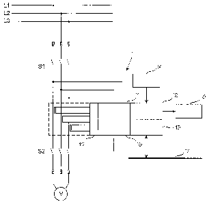
[0013] In Figure 1, a thermal overload protection is coupled be-
tween an electric motor M or other electrical device to be protected and a
three-phase mains current supply L1, L2 and L3. S1 is a main mains switch,
e.g. manually controlled, and S2 is a release switch controlled by the
overload
CA 02554117 2006-07-20
WO 2005/074089 PCT/FI2005/000066
4
protection and controlled with a trip signal TRIP. The overload protection 1
measures the current load of each phase L1, L2 and L3 of the mains current
supply of the motor M with a current measurement unit 10, which is based on
current transformers, for example. In addition, the overload protection 1 may
comprise a measuring unit 11 for measuring phase voltages. Further, the over-
load protection 1 preferably comprises a user interface, i.e. a human-machine-
interface (HMI) 12, with a display 13 and a keyboard 14. Furthermore, the
overload protection 1 may comprise a data communication unit 15 connected
to a local area network (e.g. Ethernet), a bus, a field bus (e.g. Profibus DP)
or
another data communication medium 17.
[0014] As regards the invention, the most essential function is re-
lated to the protection and control unit 16. The overload protection 'I is
imple-
mented with a microprocessor system, the majority of the above a nits being
implemented with suitable microprocessor software and peripheral circuits,
such as memory circuits. The measuring values provided by the current and
voltage-measuring units are converted into numerical, i.e. digital values with
digital/analog converters (A/D). In accordance with the basic principle of the
invention, the microprocessor system employs fixed-point arithmetic, prefera-
bly 32-bit arithmetic. A suitable processor type is for instance a general-
purpose processor having a 32-bit RISC instruction set, such as ARM7/9 or the
M68k series.
[0015] It is to be appreciated that the above-described structure is
only one example of a thermal overload protection for implementing the inven-
tion.
[0016] The overload protection 1 protects the motor M from over-
heating and from any damage caused thereby. The protection is based on cal-
culating the thermal load on the motor on the basis of measured phase cur-
rents. In the following, the general operation of the protection will be
explained
by means of the example of Figures 2 and 3. Phase conductors L1, L2 and L3
are connected to the motor M by closing switches S1 and S2. The current-
measuring unit 10, measures the currents of the phases (step 31, Figure 3),
and the control unit 16 calculates the thermal load on the motor M on the
basis
of the phase currents by using fixed-point arithmetic (step 32). The mathemati-
cal equation used in the calculation of the thermal load for one phase may be
as follows:
CA 02554117 2006-07-20
WO 2005/074089 PCT/FI2005/000066
2 1
O/~ =OT~I +C1- ~T ~~DIz-1
C RFC
wherein
O = thermal load, preferably 0 to 200% preferably corresponding to
a value range of 0 to 2.4
~T = interval for thermal load calculation, preferably in milliseconds
R = cooling factor of electrical device, preferably 1 to 10
C = trip-class factor
i = measured load current
[0017] Factor C is preferably a trip-class factor t6, which ind icates
the longest starting time set on the motor relative to the actual starting
time of
the motor. Factor C may be for instance 1.7 (x actual starting time). In a pri-
mary embodiment of the invention, the trip-class factor t6 is multiplied by a
constant, preferably 29.5, or calculated by the formula (1/k) * Te * (la/In)2,
wherein la = starting current, In = nominal current, Te = allowed starting
time,
and k = constant. Constant k = 1.22 when an operating time graph correspond-
ing to that of a combination of trip class and t6-time is desired (operating
times
according to the requirements of IEC 60947-4-1 ). The measured current is
preferably scaled into a unit value to a range of 0 to Y, wherein Y represents
Y/100% of the nominal current, and preferably Y=65000, whereby the calcula-
tion is independent of the actual current range.
[0018] Let us examine 32-bit fixed-point arithmetic by way of exam-
ple. In accordance with the invention, the above-described mathematical equa-
tion or algorithm and its operands that calculate the thermal load are pro-
grammed suitable for a processor system employing 32-bit fixed-point arithme-
tic in such a manner that the result or the provisional result never exceed
the
32-bit value when the program is run in the processor system.
[0019] The following is an example of a calculation equation struc-
tured and scaled in this manner
thRes = ( (OT* ( i2/C ) +ROUNDING) /MSEC )
+ ( ( ( ( (MSEC*SCAZING) - ( (~T*SCALING) / (R*C) ) ) /SPART7..) *th) /S~'A~T~
)
+thFract
wherein the operand values are for example as follows
thRes = thermal load 0 to 200% corresponding to value range 0 to 24.000
ROUNDING = e.g. 500
CA 02554117 2006-07-20
WO 2005/074089 PCT/FI2005/000066
6
MSEC = e.g. 1000
SCALING = e.g. 10000
SPART1 = e.g. SCALING l 10
SPART2 = e.g. SCALING l 100
thFract = thRes of previous calculation divided by constant,
e.g. constant = SCALING = 10000.
[0020] ROUNDING corresponds to decimal rounding. MSEC scales
milliseconds into seconds. SCALING is accuracy scaling. The product of terms
SPART1 and SPART2 represents the scaling of a time unit (preferably milli-
seconds), split into two parts to maintain calculation accuracy.
[0021] The result of the thermal load, thRes, is too high because of
the scaling (in the example, within the range 0 to 24000), and it is scaled
down
to represent the thermal load per unit value employed, in the example to the
range0to2.4
O = thRES/10000
[0022] This quotient O is saved as parameter thFract and employed
in the calculation the next time. Calculation accuracy on 0 to 100% thermal
load is better than 0.1 % of the thermal load.
[0023] The graph of Figure 2 represents the calculated thermal load
O as a function of time t. When the motor M is started from cold state, it
begins
to warm up. In the same way, the calculated thermal load O increases as a
function of time. When the thermal load O increases to a given set alarm level
Alarm level, the control unit 16 may give an alarm to the operator for
instance
via the user interface 12-14 or the communication unit 15 (steps 35 and 36 in
Figure 3). The control unit 16 may also continuously or after a given level
cal-
culate the remaining time to trip (time-to-trip) and communicate it to the
opera-
tor (steps 33 and 34 in Figure 3). When the thermal load O increases to a
given set trip level Trip (preferably 100% of the thermal load on the motor),
the
control unit 16 activates a trip signal TRIP, which controls the switch S2 to
open, whereby the motor M is disconnected from the three-phase supply L1,
L2 and L3 (steps 37 and 38 in Figure 3). If the thermal capacity of the motor
remaining after the tripping is too low (e.g. less than 60%), the protection 1
may prevent a restart until the motor is cooled to a given level (resfiart
inhibit)
or for a given time (steps 39 and 40 in Figure 3). For start-up, signal TRIP
is
again connected inactive and switch S2 is closed. In an embodiment, the op-
erator may control the control unit 16 into an override state, wherein the
Trip
CA 02554117 2006-07-20
WO 2005/074089 PCT/FI2005/000066
7
level is double (override Trip level).
(0024 It is obvious to a person skilled in the art that as technology
advances, the basic idea of the invention can be implemented in a variety of
ways. Consequently, the invention and its embodiments are not restricted to
the above examples, but can vary within the scope of the claims.