Language selection

Search

Patent 2554220 Summary

Third-party information liability

Some of the information on this Web page has been provided by external sources. The Government of Canada is not responsible for the accuracy, reliability or currency of the information supplied by external sources. Users wishing to rely upon this information should consult directly with the source of the information. Content provided by external sources is not subject to official languages, privacy and accessibility requirements.

Claims and Abstract availability

Any discrepancies in the text and image of the Claims and Abstract are due to differing posting times. Text of the Claims and Abstract are posted:

  • At the time the application is open to public inspection;
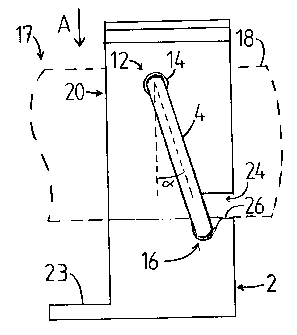
  • At the time of issue of the patent (grant).
(12) Patent: (11) CA 2554220
(54) English Title: FUSE HOLDER
(54) French Title: PORTE-FUSIBLE
Status: Granted and Issued
Bibliographic Data
(51) International Patent Classification (IPC):
  • H01H 85/20 (2006.01)
  • H01H 9/10 (2006.01)
(72) Inventors :
  • SALO, JUHO (Finland)
  • MATTLAR, HARRI (Finland)
(73) Owners :
  • ABB SCHWEIZ AG
(71) Applicants :
  • ABB SCHWEIZ AG (Switzerland)
(74) Agent: GOWLING WLG (CANADA) LLP
(74) Associate agent:
(45) Issued: 2012-07-10
(86) PCT Filing Date: 2005-02-02
(87) Open to Public Inspection: 2005-08-18
Examination requested: 2009-12-14
Availability of licence: N/A
Dedicated to the Public: N/A
(25) Language of filing: English

Patent Cooperation Treaty (PCT): Yes
(86) PCT Filing Number: PCT/FI2005/000069
(87) International Publication Number: WO 2005076306
(85) National Entry: 2006-07-21

(30) Application Priority Data:
Application No. Country/Territory Date
20045025 (Finland) 2004-02-03

Abstracts

English Abstract


A fuse holder comprising a frame (2), spring means and limiter means (6), the
frame (2) comprising a first contact member (8) and a second contact member
(10) adapted to receive an end (18) of the fuse between them, the spring means
being adapted to press the contact members (8, 10) against the fuse end (18)
to achieve an electrically conductive connection between the contact members
(8, 10) and the fuse end (18), and the limiter means (6) being adapted to
define the largest possible depth of the fuse end (18) in the installation
direction between the first (8) and second (10) contact members. The spring
means comprise a substantially circular arch-formed ring spring (4) adapted to
also serve as the limiter means (6).


French Abstract

Porte-fusible composé d'un cadre (2), de moyens élastiques et de moyens de limitation (6), le cadre (2) comprenant un premier élément de contact (8) et un deuxième élément de contact (10) conçus pour recevoir une extrémité (18) du fusible entre lesdits éléments de contact, les moyens élastiques étant conçus pour exercer une pression sur les éléments de contact (8, 10) contre l'extrémité du fusible (18) afin de créer un raccordement électrique entre lesdits éléments de contact (8, 10) et l'extrémité du fusible (18), les moyens de limitation (6) étant conçus pour définir la profondeur la plus grande possible de l'extrémité du fusible (18) dans le sens de l'installation entre le premier (8) et le deuxième (10) élément de contact. Les moyens élastiques comprennent un ressort annulaire incurvé pratiquement circulaire (4) conçu également pour servir de moyens de limitation (6).

Claims

Note: Claims are shown in the official language in which they were submitted.

6
What is claimed is:
1. A fuse holder comprising a frame, spring means and limiter means, the frame
comprising
a first contact member and a second contact member adapted to receive an end
of a fuse between
them, the spring means being adapted to press the contact members against the
fuse end to
achieve an electrically conductive connection between the contact members and
the fuse end,
and the limiter means being adapted to define a largest possible depth of the
fuse end in an
installation direction between the first and second contact members, wherein
the spring means
comprise a ring spring having substantially a form of a circular arch and
serving as the limiter
means; wherein the frame is provided with slots for supporting a middle
portion located between
ends of the ring spring; wherein the slots are provided with projections
configured to prevent the
ring spring from rotating around an axis passing via the ends; and wherein the
ring spring is
placed in such a manner that when the fuse end is at said largest possible
depth in the installation
direction between the contact members, the fuse end is in contact with the
middle portion located
between the ends of the ring spring.
2. A fuse holder as claimed in claim 1, wherein the ring spring is located
substantially on a
plane that is at a predetermined angle (.alpha.) relative to the installation
direction of the fuse end.
3. A fuse holder as claimed in claim 2, wherein said predetermined angle
(.alpha.) is between 0 °
and 45°.
4. A fuse holder as claimed in claim 1, wherein the frame is provided with
means for
holding the ends of the ring spring in place.
5. A fuse holder as claimed in claim 4, wherein said means for holding the
ends of the ring
spring in place comprise two recesses provided in the frame, each recess being
adapted to receive
a corresponding end of the ring spring.
6. A fuse holder as claimed in claim 1, wherein the means for supporting the
middle portion
located between the ends of the ring spring are adapted to support the middle
portion of the ring
spring in a direction opposite relative to the installation direction of the
fuse end.
7. A fuse holder as claimed in claim 1, wherein the cross-section of the frame
is

7
substantially U-shaped in such a manner that a first branch of the frame
comprises the first
contact member, and a second branch of the frame comprises the second contact
member.

Description

Note: Descriptions are shown in the official language in which they were submitted.


CA 02554220 2006-07-21
WO 2005/076306 PCT/FI2005/000069
1
FUSE HOLDER
BACKGROUND OF THE INVENTION
[0001] The invention relates to fuse holders according to the pre-
amble of the independent claim.
[0002] A known fuser holder comprises a frame provided with a first
and a second contact member, between which one end of the fuse is placed,
spring means for pressing the contact members against the end of the fuse for
achieving an electrically conductive connection, and limiter means for
defining
the largest allowed depth of the fuse end in the installation direction
between
the contact members. In known fuse holders, the limiter means are achieved
by frame design or with a separate component.
[0003] The problem in the above-described fuse holder is its com-
plex structure.
BRIEF DESCRIPTION OF THE INVENTION
[0004] The object of the invention is thus to provide a fuse holder al-
lowing the above problem to be solved. The object of the invention is achieved
with a fuse holder, which is characterized in what is stated in the
independent
claim. Preferred embodiments of the invention are described in the dependent
claims.
[0005] The invention is based on using the spring means also as
the limiter means.
[0006] An advantage of the fuse holder of the invention is a simple
structure that is easy to assemble.
BRIEF DESCRIPTION OF THE FIGURES
[0007] In the following, the invention will be described in more detail
in connection with preferred embodiments with reference to the accompanying
drawings, in which
Figure 1 is a side view of a fuse holder according to an embodiment
of the invention; and
Figure 2 shows the fuse holder of Figure 1 seen in the axial direc-
tion.
DETAILED DESCRIPTION OF THE INVENTION
[0008] Figures 1 and 2 show a fuse holder adapted to receive one

CA 02554220 2006-07-21
WO 2005/076306 PCT/FI2005/000069
2
end of a fuse. Accordingly, the installation of one fuse requires two fuse
hold-
ers, the first of which receives a first axial end of the fuse, the second
receiving
a second axial end of the fuse. Figures 1 and 2 show, with a dashed line, an
end 18 of a fuse 17, the end being adapted for an electric connection of the
fuse 17.
[0009] The fuse holder of Figures 1 and 2 comprises a frame 2,
spring means and limiter means 6. The frame 2 comprises a first contact
member 8 and a second contact member 10 adapted to receive the fuse end
18 between them. The spring means comprise a ring spring 4 having substan-
tially the form of a circular arch and adapted to also serve as the limiter
means
6. The spring means are adapted to press the contact means 8 and 10 against
the fuse end 18 to achieve an electrically conductive connection between the
contact members and the fuse end 18. The limiter means 6, i.e. the middle por-
tion of the ring spring 4, are adapted to define the largest possible depth of
the
fuse end 18 in the installation direction between the first 8 and second 10
con-
tact members. Herein, the installation direction refers to the direction in
which
the fuse end 18 is moved between the contact members 8 and 10 during the
installation of the fuse. In Figures 1 and 2, the installation direction is
substan-
tially vertical, and denoted by arrow A in Figure 1.
[0010] In Figures 1 and 2, the fuse end 18 is at the largest possible
depth in the installation direction between the contact members 8 and 10, the
fuse end 18 being in contact with the middle portion located between the ends
of the ring spring 4.
[0011] The cross-section of the frame 2 of the fuse holder is sub-
stantially U-shaped, and the frame is manufactured from one planar perform by
bending. A first branch 20 of the frame 2 comprises the first contact member
8,
and a second branch 22 of the frame comprises the second contact member
10. The contact members 8 and 10 are substantially vertical and substantially
parallel.
[0012] Figure 2 shows that the lower portion of the frame 2 broad-
ens, whereby the branches 20 and 22 first diverge from one another such that
they are at an about 30-degree angle relative to vertical, after which the
branches 20 and 22 approach each other converging at the mid line of the fuse
holder. The bottom of the frame 2 is substantially horizontal.
[0013] Because of the width of the lower portion of the frame 2, it is
easy to fasten the fuse holder to an electrical appliance, such as a switch-
fuse.

CA 02554220 2006-07-21
WO 2005/076306 PCT/FI2005/000069
3
The solidity of the fastening is also enhanced by a projection 23 at the
bottom
of the frame 2.
[0014] The fuse holder frame 2 according to the figures is made
from an electrically conductive material. The frame 2 is preferably made from
an elastic electrically conductive material, such as copper, whereby the frame
2 is able to assist the ring spring 4 by forcing the contact members 8 and 10
against the fuse end 18.
[0015] The frame 2 is provided with means 12 for holding the ends
of the ring spring 4 in place. The means 12 for holding the ends of the ring
spring in place comprise two recesses 14, each of which is provided on the
outer surface of the corresponding branch of the frame 2. The recesses 14 are
provided at the upper portion of the frame 2, i.e. the portion from whose
direc-
tion the fuse end 18 is pushed in between the branches 20 and 22. The cross-
section of each recess 14 is round, the recessed being adapted to receive the
corresponding end of the ring spring. The mid lines of the recesses 14 are
substantially parallel. The recesses 14 are provided in the branches 20 and 22
by punching.
[0016] Figure 2 shows that the upper ends of the branches 20 and
22 of the frame 2 are bent outwards. Such a design facilitates the
installation of
the fuse end 18.
[0017] The ends of the ring spring 4 are installed in corresponding
recesses 14. The ring spring 4 is located on a plane at a predetermined angle
a relative to the installation direction of the fuse end 18. In the fuse
holder of
Figure 1, angle a is about 15°, the ring spring 4 being directed
outwards rela-
tive to the axial direction of the fuse 17. Alternatively, the ring spring 4
can be
directed inwards relative to the axial direction of the fuse, the middle
portion of
the ring spring being axially closer to the middle portion of the fuse than
the
ends of the ring spring.
[0018] Angle a may vary between 0° and 90°. In the case of a
fuse
holder of the type of Figure 1, angle a is preferably between 0° and
45°.
[0019] The frame 2 is provided with means 16 for supporting the
middle portion located between the ends of the ring spring. The means 16 are
intended to prevent the ends of the ring spring 4 from being detached from the
recesses 14 during installation of the fuse end 18 into the fuse holder. The
means 16 support the middle portion of the ring spring in a direction opposite
relative to the installation direction of the fuse end.

CA 02554220 2006-07-21
WO 2005/076306 PCT/FI2005/000069
4
[0020] The means 16 for supporting the middle portion of the ring
spring comprise two slots 24, each being provided in the corresponding branch
of the frame 2. The slots 24 in branch 20 and branch 22 are located and
shaped as each other's mirror images relative to the mid line of the fuse
holder.
[0021] Each slot 24 is located in the corresponding branch at the
boundary of the vertical portion and the portion at an about 30-degree angle
relative to vertical in such a manner that the slot extends in both said
portions.
In the axial direction of the fuse 17, each slot 24 extends to the
corresponding
branch of the frame along a stretch that is approximately triple relative to
the
thickness of the ring spring 4. The height of each slot 24, i.e. the dimension
parallel to the installation direction of the fuse, is also about triple
relative to the
thickness of the ring spring 4.
[0022] The orifice of each slot 24 is provided with a projection 26
limiting the height of the orifice of the slot to about half of the total
height of the
slot. The projections 26 are shaped such that, with the ring spring 4
installed in
the fuse holder, the ring spring is substantially unable to rotate around the
axis
passing via its ends, whereby the ring spring remains in its desired position.
[0023] Installing the ring spring in the frame 2 presented in Figures
1 and 2 is easy. In one alternative, the middle portion of the ring spring 4
is
arranged to pass via the slots 24, after which the ends of the ring spring 4
are
bend farther from one another, allowing them to be placed in the correspond-
ing recesses. The branches 20 and 22 of the frame 2 can be bent towards one
another to facilitate the installation.
[0024] In an alternative embodiment of the invention, the means 12
for holding the ends of the ring spring in position are so solid that no
separate
means 16 for supporting the middle portion located between the ends of the
ring spring are required. For example, providing sufficiently deep recesses 14
ensures that the ends of the ring spring 4 are not detached from the recesses,
even though the fuse end 18 directs forces in the installation direction to
the
middle portion of the ring spring.
[0025] The fuse holder shown in the figures is adapted for fuses
with ends whose cross-sections are in the form of a rectangular parallelogram.
The contact members of the fuse holder according to the invention may also
be adapted suitable for other types of fuses.
[0026] It is obvious to a person skilled in the art that the basic idea

CA 02554220 2006-07-21
WO 2005/076306 PCT/FI2005/000069
of the invention can be implemented in a variety of ways. Consequently, the
invention and its embodiments are not restricted to the above examples, but
can vary within the scope of the claims.

Representative Drawing
A single figure which represents the drawing illustrating the invention.
Administrative Status

2024-08-01:As part of the Next Generation Patents (NGP) transition, the Canadian Patents Database (CPD) now contains a more detailed Event History, which replicates the Event Log of our new back-office solution.

Please note that "Inactive:" events refers to events no longer in use in our new back-office solution.

For a clearer understanding of the status of the application/patent presented on this page, the site Disclaimer , as well as the definitions for Patent , Event History , Maintenance Fee  and Payment History  should be consulted.

Event History

Description Date
Common Representative Appointed 2019-10-30
Letter Sent 2019-05-03
Inactive: Multiple transfers 2019-04-17
Change of Address or Method of Correspondence Request Received 2018-01-10
Grant by Issuance 2012-07-10
Inactive: Cover page published 2012-07-09
Pre-grant 2012-04-25
Inactive: Final fee received 2012-04-25
Notice of Allowance is Issued 2012-04-12
Letter Sent 2012-04-12
Notice of Allowance is Issued 2012-04-12
Inactive: Approved for allowance (AFA) 2012-04-02
Amendment Received - Voluntary Amendment 2011-08-22
Inactive: S.30(2) Rules - Examiner requisition 2011-02-24
Letter Sent 2010-01-21
Request for Examination Requirements Determined Compliant 2009-12-14
All Requirements for Examination Determined Compliant 2009-12-14
Amendment Received - Voluntary Amendment 2009-12-14
Request for Examination Received 2009-12-14
Letter Sent 2006-10-13
Inactive: Correspondence - Transfer 2006-09-28
Inactive: Courtesy letter - Evidence 2006-09-19
Inactive: Cover page published 2006-09-19
Inactive: Notice - National entry - No RFE 2006-09-15
Inactive: Single transfer 2006-09-08
Application Received - PCT 2006-08-30
National Entry Requirements Determined Compliant 2006-07-21
Application Published (Open to Public Inspection) 2005-08-18

Abandonment History

There is no abandonment history.

Maintenance Fee

The last payment was received on 2012-01-30

Note : If the full payment has not been received on or before the date indicated, a further fee may be required which may be one of the following

  • the reinstatement fee;
  • the late payment fee; or
  • additional fee to reverse deemed expiry.

Please refer to the CIPO Patent Fees web page to see all current fee amounts.

Owners on Record

Note: Records showing the ownership history in alphabetical order.

Current Owners on Record
ABB SCHWEIZ AG
Past Owners on Record
HARRI MATTLAR
JUHO SALO
Past Owners that do not appear in the "Owners on Record" listing will appear in other documentation within the application.
Documents

To view selected files, please enter reCAPTCHA code :


To view images, click a link in the Document Description column. To download the documents, select one or more checkboxes in the first column and then click the "Download Selected in PDF format (Zip Archive)" or the "Download Selected as Single PDF" button.

List of published and non-published patent-specific documents on the CPD .

If you have any difficulty accessing content, you can call the Client Service Centre at 1-866-997-1936 or send them an e-mail at CIPO Client Service Centre.


Document
Description 
Date
(yyyy-mm-dd) 
Number of pages   Size of Image (KB) 
Abstract 2006-07-21 2 83
Description 2006-07-21 5 218
Claims 2006-07-21 2 70
Drawings 2006-07-21 1 19
Representative drawing 2006-09-19 1 6
Cover Page 2006-09-19 1 37
Claims 2009-12-14 2 57
Cover Page 2012-06-14 2 41
Maintenance fee payment 2024-01-22 45 1,844
Reminder of maintenance fee due 2006-10-03 1 110
Notice of National Entry 2006-09-15 1 192
Courtesy - Certificate of registration (related document(s)) 2006-10-13 1 105
Reminder - Request for Examination 2009-10-05 1 116
Acknowledgement of Request for Examination 2010-01-21 1 176
Commissioner's Notice - Application Found Allowable 2012-04-12 1 163
PCT 2006-07-21 5 137
Correspondence 2006-08-16 3 74
Correspondence 2006-09-15 1 26
Correspondence 2012-04-25 2 51