Language selection

Search

Patent 2554521 Summary

Third-party information liability

Some of the information on this Web page has been provided by external sources. The Government of Canada is not responsible for the accuracy, reliability or currency of the information supplied by external sources. Users wishing to rely upon this information should consult directly with the source of the information. Content provided by external sources is not subject to official languages, privacy and accessibility requirements.

Claims and Abstract availability

Any discrepancies in the text and image of the Claims and Abstract are due to differing posting times. Text of the Claims and Abstract are posted:

  • At the time the application is open to public inspection;
  • At the time of issue of the patent (grant).
(12) Patent: (11) CA 2554521
(54) English Title: SPRING ELEMENT FOR RAIL VEHICLES
(54) French Title: ELEMENT RESSORT DESTINE A VEHICULES SUR RAILS
Status: Expired and beyond the Period of Reversal
Bibliographic Data
(51) International Patent Classification (IPC):
  • F16F 01/376 (2006.01)
  • F16F 01/44 (2006.01)
(72) Inventors :
  • GEDENK, VOLKER (Germany)
  • KROPF, ANDREAS (Germany)
  • HOPPMANN, FRIEDRICH (Germany)
(73) Owners :
  • CONTITECH LUFTFEDERSYSTEME GMBH
(71) Applicants :
  • CONTITECH LUFTFEDERSYSTEME GMBH (Germany)
(74) Agent: SMART & BIGGAR LP
(74) Associate agent:
(45) Issued: 2013-02-05
(86) PCT Filing Date: 2004-12-08
(87) Open to Public Inspection: 2005-08-11
Examination requested: 2009-10-09
Availability of licence: N/A
Dedicated to the Public: N/A
(25) Language of filing: English

Patent Cooperation Treaty (PCT): Yes
(86) PCT Filing Number: PCT/EP2004/053326
(87) International Publication Number: EP2004053326
(85) National Entry: 2006-07-25

(30) Application Priority Data:
Application No. Country/Territory Date
04001874.9 (European Patent Office (EPO)) 2004-01-29

Abstracts

English Abstract


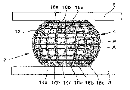
The invention relates to a spring element (2) consisting essentially of an
elastic spring body (4) that is fixed between two rigid end parts (6, 8)
arranged at a variable distance from each other. Said spring body (4)
consisting of rubber or a rubber-type plastic has a rotationally symmetrical
cross-section, the longitudinal section having a biconvex surface line. A U-
shaped cross-section is formed as a result of a recess (10). The aim of the
invention is to reduce the abrasion caused by the introduction of vertical and
horizontal forces and to enable a light, horizontal slide. The surface (12) of
the spring body (4) is provided with ribs (14; 14a, ...) that are arranged at
a distance (A) from each other and are intersected by ribs (16; 16a, ...) or
groups of ribs (16, ...) also arranged at a distance (A) from each other.
Polygonal fields (18a, ...) are formed on the surface (12) of the spring body
(4), in the gaps between the ribs (14, ...; 16, ...), according to the angle
of intersection. Instead of the ribbing, or in addition thereto, the spring
body (4) and/or the surface of at least one of the end bodies (6 and/or 8) can
be provided with a smooth surface. The ribs (14a, ...; 16a, ...) are
preferably approximately 2 mm thick and approximately 10 mm apart. The
inventive spring element is especially used as an additional spring combined
with a pneumatic spring in rail vehicles.


French Abstract

L'invention concerne un élément ressort (2) essentiellement composé d'un corps ressort élastique (4) fixé entre deux corps terminaux rigides (6, 8) dont l'écart varie. Le corps ressort (4) réalisé en caoutchouc ou dans un matériau de type caoutchouc présente une section transversale à symétrie de rotation, la section longitudinale présentant une ligne de surface biconvexe. En raison d'un évidement (10), la section transversale totale est en forme de U. L'invention vise à réduire l'usure provoquée par des forces verticales et horizontales et à permettre un coulissage horizontal aisé. La surface (12) du corps ressort (4) comporte des nervures (14; 14a, ) disposées à un écart (A), coupées par des nervures (16; 16a, ) ou des groupes de nervures (16, ) également disposées à un écart (A). Sur la surface (12) du corps ressort (4), des champs polygonaux (18a, ) sont formés selon l'angle de coupe dans les interstices entre les nervures (14, ...; 16, ...). A la place ou en plus des nervures, le corps ressort (4) et/ou la surface d'au moins un des corps ressort (6 et/ou 8) peuvent comporter une surface lisse. Les nervures (14a, ...; 16a, ...) présentent de préférence une épaisseur d'environ 2 mm et un écart d'environ 10 mm. L'élément ressort selon l'invention est notamment destiné à être employé en tant que ressort supplémentaire en combinaison avec un ressort pneumatique dans des véhicules sur rails.

Claims

Note: Claims are shown in the official language in which they were submitted.


6
CLAIMS:
1. A spring comprising:
first and second rigid end members moveable relative to each other
causing the distance therebetween to vary during operation of said spring;
an elastic spring body mounted between said end members;
said elastic spring body having a rotationally symmetrical cross section
and a longitudinal section having biconvex shape;
said elastic spring body being a monolithic body of rubber or a rubber-
like plastic and having a surface which is pressed with more or less area of
said
surface against said rigid end members as said distance becomes shorter or
longer
during said operation;
a first plurality of ribs arranged on said surface spaced one from the
other at respective first distances;
a second plurality of ribs arranged on said surface spaced one from the
other at respective second distances;
said second plurality of ribs intersecting said first plurality of ribs so as
to form a multiplicity of intermediate spaces defining a corresponding
plurality of
polygonal areas or cavities on said surface wherein air collects to become
trapped
between said spring body and said rigid end members to form a plurality of air
pillows
as said rigid end members move toward each other so as to permit said elastic
spring
body to slide on said air pillows;
said elastic spring body having a substantially U-shaped cavity formed
therein so as to impart said biconvex shape to said elastic spring body when
viewed
in longitudinal section; and,

7
one of said rigid end members having an opening formed therein lying
opposite said U-shaped cavity to permit said U-shaped cavity to communicate
with
the ambient.
2. The spring of claim 1, wherein a surface coating to facilitate sliding is
provided on at least one of said elastic spring body, said first end member
and said
second end member.
3. The spring of claim 2, wherein said first plurality of ribs are mutually
parallel and said second plurality of ribs are mutually parallel and intersect
said first
plurality of ribs orthogonally.
4. The spring of claim 3, wherein said first plurality of ribs are spaced
approximately 10 mm one from the other; and, said second plurality of ribs are
spaced approximately 10 mm one from the other.
5. The spring of claim 4, wherein said ribs each have a height of
approximately 2 mm.
6. The spring of claim 5, wherein said ribs are configured as wear or
abrasion ribs.
7. The spring of claim 6, wherein said ribs are made of a material which
differs from the material of said spring body.
8. The spring of claim 7, wherein said ribs have a surface to facilitate
sliding.
9. The spring of claim 1, wherein the ribs of said first and second plurality
of ribs all have the same height.
10. The spring of claim 1, wherein said one rigid end member is a flat
annular member defining said opening; and, the other one of said rigid end
members
is a flat disc-shaped member.

8
11. A spring comprising:
first and second rigid end members moveable relative to each other
causing the distance therebetween to vary;
an elastic spring body mounted between said end members so as to act
solely by itself as a spring between said rigid end members;
said elastic spring body having a rotationally symmetrical cross section
and a longitudinal section having biconvex shape;
said elastic spring body having a surface and being a monolithic body of
rubber or a rubber-like plastic;
a first plurality of ribs arranged on said surface spaced one from the
other at respective first distances and said first plurality of ribs having a
predetermined height;
a second plurality of ribs arranged on said surface spaced one from the
other at respective second distances and said second plurality of ribs having
a height
equal to said predetermined height;
said second plurality of ribs intersecting said first plurality of ribs so as
to form a multiplicity of intermediate spaces defining a corresponding
plurality of
polygonal cavities on said surface wherein air collects to become trapped
between
said spring body and said rigid end members to form a plurality of air pillows
as said
rigid end members move toward each other so as to permit said elastic spring
body
to slide on said air pillows;
said elastic spring body having a cavity formed therein so as to impart
said biconvex shape to said elastic spring body when viewed in longitudinal
section;
and,

9
one of said rigid end members having an opening formed therein lying
opposite said cavity to permit said cavity to communicate with the ambient.
12. The spring of claim 11, wherein a surface coating to facilitate sliding is
provided on at least one of said elastic spring body, said first end member
and said
second end member.
13. The spring of claim 12, wherein said first plurality of ribs are mutually
parallel and said second plurality of ribs are mutually parallel and intersect
said first
plurality of ribs orthogonally.
14. The spring of claim 13, wherein said first plurality of ribs are spaced
approximately 10 mm one from the other; and, said second plurality of ribs are
spaced approximately 10 mm one from the other.
15. The spring of claim 14, wherein said ribs each have a height of
approximately 2 mm.
16. The spring of claim 15, wherein said ribs are configured as wear or
abrasion ribs.
17. The spring of claim 16, wherein said ribs are made of a material which
differs from the material of said spring body.
18. The spring of claim 17, wherein said ribs have a surface to facilitate
sliding.
19. The spring of claim 11, wherein said one rigid end member is a flat
annular member defining said opening; and, the other one of said rigid end
members
is a flat disc-shaped member.

Description

Note: Descriptions are shown in the official language in which they were submitted.


CA 02554521 2011-08-16
27829-20
DESCRIPTION 1
SPRING ELEMENT FOR RAIL VEHICLES
The invention relates to a spring element and especially to
a so-called layer spring which can be used by itself or as an
ancillary spring in combination with an air spring in a railroad
vehicle
STATE OF THE ART
A spring element for vehicle suspensions is disclosed in the
patent DE 35 09 923 C2. The essential features of this spring
element are described in the first paragraphs of the disclosure.
The outer contour of the rubber body of the known spring
element is smooth. Because of continuously alternating vertical
forces, the support surface of the rubber body increases and
decreases. The rubber body rolls off on the lower support
because of the additionally introduced horizontal forces. Both
result in relative movements between the rubber and the support
and therefore in friction and wear of the rubber.
TASK OF THE INVENTION
The spring element known from the above-mentioned state of
the art is to be improved in such a manner that, during the
introduction of vertical and horizontal forces, the wear of the
rubber is reduced and a easy horizontal sliding is made possible.
SOLUTION AND ADVANTAGES
The spring element of the invention having the
characterizing features of the main claim affords the advantage
with respect to the known springs that the ribs on the spring
surface form small polygons, especially quadrilaterals (rhombi,
rectangles, squares). When the spring element is pressed onto
the support, air collects in these polygons. For this reason,

CA 02554521 2011-08-16
27829-20
2
the spring body slides on.a plurality of air pillows. Therefore,
there is only friction between the rubber ribs and the support
surface.
In lieu of the ribbed spring surface or additionally, the
entire surface of the spring body including possibly the rib
surface and/or the surface of the rigid end bodies arranged
relative to each other at a variable spacing can be provided with
a sliding surface whereby an abrading action is substantially
avoided during the deformation of the loaded spring body.
in a constructive configuration of the ribs arranged on the
spring body, it has been shown to be especially advantageous when
the ribs are approximately 2 mm high and are mutually spaced
approximately 10 mm from each other.
The surface of the ribs can be made from a slide capable
material in order to further reduce the coefficient of friction
of the spring body. The ribs are preferably configured as
so-called wear ribs with the material of these wear ribs being
different from the material of the spring body.
The ribs are so configured and dimensioned that they outlive
the time of use of the spring element.
With the different measures, a longer use time of the spring
element is ensured. The characteristic line of the spring is not
influenced by the different friction on the support surface.

CA 02554521 2011-08-16
27829-20
2a
According to one aspect of the present invention, there is provided a
spring comprising: first and second rigid end members moveable relative to
each
other causing the distance therebetween to vary during operation of said
spring; an
elastic spring body mounted between said end members; said elastic spring body
having a rotationally symmetrical cross section and a longitudinal section
having
biconvex shape; said elastic spring body being a monolithic body of rubber or
a
rubber-like plastic and having a surface which is pressed with more or less
area of
said surface against said rigid end members as said distance becomes shorter
or
longer during said operation; a first plurality of ribs arranged on said
surface spaced
one from the other at respective first distances; a second plurality of ribs
arranged on
said surface spaced one from the other at respective second distances; said
second
plurality of ribs intersecting said first plurality of ribs so as to form a
multiplicity of
intermediate spaces defining a corresponding plurality of polygonal areas or
cavities
on said surface wherein air collects to become trapped between said spring
body and
said rigid end members to form a plurality of air pillows as said rigid end
members
move toward each other so as to permit said elastic spring body to slide on
said air
pillows; said elastic spring body having a substantially U-shaped cavity
formed
therein so as to impart said biconvex shape to said elastic spring body when
viewed
in longitudinal section; and, one of said rigid end members having an opening
formed
therein lying opposite said U-shaped cavity to permit said U-shaped cavity to
communicate with the ambient.
According to another aspect of the present invention, there is provided
a spring comprising: first and second rigid end members moveable relative to
each
other causing the distance therebetween to vary; an elastic spring body
mounted
between said end members so as to act solely by itself as a spring between
said rigid
end members; said elastic spring body having a rotationally symmetrical cross
section and a longitudinal section having biconvex shape; said elastic spring
body
having a surface and being a monolithic body of rubber or a rubber-like
plastic; a first
plurality of ribs arranged on said surface spaced one from the other at
respective first

CA 02554521 2011-08-16
27829-20
2b
distances and said first plurality of ribs having a predetermined height; a
second
plurality of ribs arranged on said surface spaced one from the other at
respective
second distances and said second plurality of ribs having a height equal to
said
predetermined height; said second plurality of ribs intersecting said first
plurality of
ribs so as to form a multiplicity of intermediate spaces defining a
corresponding
plurality of polygonal cavities on said surface wherein air collects to become
trapped
between said spring body and said rigid end members to form a plurality of air
pillows
as said rigid end members move toward each other so as to permit said elastic
spring
body to slide on said air pillows; said elastic spring body having a cavity
formed
therein so as to impart said biconvex shape to said elastic spring body when
viewed
in longitudinal section; and, one of said rigid end members having an opening
formed
therein lying opposite said cavity to permit said cavity to communicate with
the
ambient.
DRAWINGS
In the following, an embodiment of the invention is described with
reference to the drawings wherein:
FIG. 1 is a front elevation view of a spring element of the invention
shown in the unloaded state;
FIG. 2 is a vertical longitudinal section view of the same spring element
likewise in the unloaded state;

CA 02554521 2006-07-25
FIG. 3 is a front elevation view of the same spring element
shown in the loaded state; and,
FIG. 4 is a vertical longitudinal section of the same spring
element likewise in the loaded state.
DESCRIPTION
The spring element 2 shown in FIGS. 1 to 4 is a so-called
layer spring which can be used by itself as a support spring but
also as an additional spring in combination with an air spring
for supporting the chassis of a rail vehicle.
The spring element 2 essentially comprises an elastic spring
body 4 which is attached between two rigid members (6, 8) which
are arranged at a variable spacing from each other.
The spring body 4 has a rotationally symmetrical cross
section. The longitudinal section (FIGS. 2 and 4) shows an
approximately biconvex surface line. A U-shaped cross section
results overall because of a cavity 10.
The spring body 4 is of rubber or an elastomeric material of
comparable elastic characteristics.
The rigid upper end member 6 has a disc shape and the rigid
lower end member 8 is of annular configuration. More
specifically, the lower end member 8 has an opening 8a at its
center whereby the cavity 10, which is provided in the spring
body 4, is connected to the ambient.
The above described assembly is known from the state of the
art and is not the object of the present invention. The present
invention is directed to the surface configuration of such spring
bodies 4.
As can especially be seen in the lateral views of FIGS. 1
and 3, perpendicularly running ribs 14a and horizontally running
ribs 16a are arranged on the surface 12 of the spring body 4 in
3

CA 02554521 2006-07-25
the manner of degrees of longitude and latitude on a globe.
These ribs (14a, ...) and (16a, ...) are approximately 2 mm thick
and are positioned at spacings A of approximately 10 mm from each
other on the surface 12 whereby a plurality of small enclosed
quadrilaterals (18a, ...) is formed.
When the spring body 4 is pressed against the end
members (6, 8) functioning as supports, the air builds up which
is trapped within the quadrilaterals (18a, ...) between the
spring body 4 and the support 6 and/or support 8. When the
relative dimensions between the spring body 4 and the respective
supports 6 and 8 change with respect to each other because of
forces acting on the spring 2, then the spring body 4 does not
rub on the supports 6 and 8, but instead, the spring body 4
consisting of rubber slides on the many small air pillows. The
above force action can be vertical as well as horizontal whereby
a movement in the corresponding direction results. In this way,
there is friction only between the rubber ribs (14a, ...)
and (16a, ...) and the respective surfaces of the supports 6
and 8.
4

CA 02554521 2006-07-25
REFERENCE NUMERALS
2 spring element
4 spring body
6, 8 end members, support(s)
6 upper disc-shaped support member
8 lower annularly-shaped support member
8a opening in the lower support member
cavity
12 surface of the spring body
10 14; 14a, .., perpendicular ribs on the spring body
16; 16a, ... horizontal ribs on the spring body
A spacing between two ribs
18a, ... quadrilaterals, fields enclosed by ribs (14, 16)
5

Representative Drawing
A single figure which represents the drawing illustrating the invention.
Administrative Status

2024-08-01:As part of the Next Generation Patents (NGP) transition, the Canadian Patents Database (CPD) now contains a more detailed Event History, which replicates the Event Log of our new back-office solution.

Please note that "Inactive:" events refers to events no longer in use in our new back-office solution.

For a clearer understanding of the status of the application/patent presented on this page, the site Disclaimer , as well as the definitions for Patent , Event History , Maintenance Fee  and Payment History  should be consulted.

Event History

Description Date
Time Limit for Reversal Expired 2024-07-22
Letter Sent 2023-12-08
Letter Sent 2023-06-08
Letter Sent 2022-12-08
Common Representative Appointed 2019-10-30
Change of Address or Method of Correspondence Request Received 2018-03-28
Grant by Issuance 2013-02-05
Inactive: Cover page published 2013-02-04
Pre-grant 2012-11-07
Inactive: Final fee received 2012-11-07
Notice of Allowance is Issued 2012-05-07
Letter Sent 2012-05-07
Notice of Allowance is Issued 2012-05-07
Inactive: Approved for allowance (AFA) 2012-05-03
Amendment Received - Voluntary Amendment 2011-08-16
Inactive: S.30(2) Rules - Examiner requisition 2011-06-08
Letter Sent 2010-04-08
Inactive: Delete abandonment 2010-04-01
Inactive: Adhoc Request Documented 2010-04-01
Inactive: Abandon-RFE+Late fee unpaid-Correspondence sent 2009-12-08
Amendment Received - Voluntary Amendment 2009-10-09
Request for Examination Requirements Determined Compliant 2009-10-09
All Requirements for Examination Determined Compliant 2009-10-09
Request for Examination Received 2009-10-09
Letter Sent 2007-04-02
Correct Applicant Request Received 2007-02-16
Inactive: Single transfer 2007-02-16
Inactive: Courtesy letter - Evidence 2006-09-26
Inactive: Cover page published 2006-09-26
Inactive: Notice - National entry - No RFE 2006-09-22
Inactive: Applicant deleted 2006-09-01
Application Received - PCT 2006-09-01
National Entry Requirements Determined Compliant 2006-07-25
Application Published (Open to Public Inspection) 2005-08-11

Abandonment History

There is no abandonment history.

Maintenance Fee

The last payment was received on 2012-11-22

Note : If the full payment has not been received on or before the date indicated, a further fee may be required which may be one of the following

  • the reinstatement fee;
  • the late payment fee; or
  • additional fee to reverse deemed expiry.

Patent fees are adjusted on the 1st of January every year. The amounts above are the current amounts if received by December 31 of the current year.
Please refer to the CIPO Patent Fees web page to see all current fee amounts.

Owners on Record

Note: Records showing the ownership history in alphabetical order.

Current Owners on Record
CONTITECH LUFTFEDERSYSTEME GMBH
Past Owners on Record
ANDREAS KROPF
FRIEDRICH HOPPMANN
VOLKER GEDENK
Past Owners that do not appear in the "Owners on Record" listing will appear in other documentation within the application.
Documents

To view selected files, please enter reCAPTCHA code :


To view images, click a link in the Document Description column (Temporarily unavailable). To download the documents, select one or more checkboxes in the first column and then click the "Download Selected in PDF format (Zip Archive)" or the "Download Selected as Single PDF" button.

List of published and non-published patent-specific documents on the CPD .

If you have any difficulty accessing content, you can call the Client Service Centre at 1-866-997-1936 or send them an e-mail at CIPO Client Service Centre.

({010=All Documents, 020=As Filed, 030=As Open to Public Inspection, 040=At Issuance, 050=Examination, 060=Incoming Correspondence, 070=Miscellaneous, 080=Outgoing Correspondence, 090=Payment})


Document
Description 
Date
(yyyy-mm-dd) 
Number of pages   Size of Image (KB) 
Abstract 2006-07-24 1 32
Drawings 2006-07-24 2 158
Description 2006-07-24 5 151
Claims 2006-07-24 2 50
Representative drawing 2006-09-24 1 28
Description 2011-08-15 7 225
Claims 2011-08-15 4 134
Reminder of maintenance fee due 2006-09-24 1 110
Notice of National Entry 2006-09-21 1 192
Courtesy - Certificate of registration (related document(s)) 2007-04-01 1 105
Reminder - Request for Examination 2009-08-10 1 125
Acknowledgement of Request for Examination 2010-04-07 1 179
Commissioner's Notice - Application Found Allowable 2012-05-06 1 163
Commissioner's Notice - Maintenance Fee for a Patent Not Paid 2023-01-18 1 541
Courtesy - Patent Term Deemed Expired 2023-07-19 1 536
Commissioner's Notice - Maintenance Fee for a Patent Not Paid 2024-01-18 1 541
PCT 2006-07-24 4 211
Correspondence 2006-09-21 1 26
Correspondence 2007-02-15 1 49
Correspondence 2012-11-06 2 62