Note: Descriptions are shown in the official language in which they were submitted.
CA 02554567 2006-07-21
WO 2005/069972 PCT/US2005/002090
DISC BRAKE ROTOR ASSEMBLY AND METHOD FOR PRODUCING SAME
FIELD OF THE INVENTION
The invention generally relates to vehicle brakes, and more particularly to
novel light-
weight disc brake rotor assemblies.
CROSS-REFERENCE TO RELATED APPLICATIONS
This application claims the benefit of priority to U.S. Provisional Patent
Application
Serial Numbers 60/558,761, filed O1 April 2004, and 60/538,274, filed 21
January 2004, both of
which are incorporated by reference herein in their entirety.
BACKGROUND
Conventional brake drums and brake disc rotors are manufactured from ductile
iron, cast
iron or steel. Such drums and rotors have mechanical and thermal properties
sufficient to meet
most practical requirements of drum and disc brake systems, but they are
relatively heavy and
adversely affect performance and fuel economy.
Attempts have been made to reduce the weight of brake drums and brake discs by
manufacturing them from lighter materials such as aluminum and aluminum
alloys. However,
while aluminum and aluminum alloys, such as '319' or '356,' are relatively
light, they do not
possess adequate mechanical properties (e.g., high temperature strength,
hardness and wear
resistance) typically required for brake applications, including for disc
brake applications.
Brake drums and brake discs have been homogeneously fabricated from aluminum-
based
2o metal matrix composite (MMC), comprising silicon carbide particulate
reinforcement. Such
aluminum MMC provides for reduced weight, improved mechanical and thermal
properties
relative to aluminum and aluminum alloys, and is commercially available, for
example, under
the name DURALCAN~ (Alcan Aluminum Limited). However, there are significant
disadvantages with such homogeneous MMC castings. MMC casting are expensive
relative to
iron and conventional aluminum alloys. Additionally, compared to iron and
conventional
aluminum castings, aluminum MMC castings are relatively difficult to machine
because of the
silicon particulate reinforcement.
CA 02554567 2006-07-21
WO 2005/069972 PCT/US2005/002090
Disc brake rotors comprising 'friction plates' have been described, in which
only the
friction plate portions of the rotor assembly are formed of a reinforced
aluminum alloy, while
the remainder of the brake disc rotor is a conventional aluminum alloy (e.g.,
'319' or '356').
Such prior art friction plate-bearing brake disc rotors are constructed by
securing a reinforced
aluminum alloy preform mixture into a conforming annular recessed portion of
the disc brake
rotor body (U.S. Patent No. 5,183,632). Additionally, generally hat-shaped
rotor bodies
comprised of a conventional alloy have been cast in situ with a precast MMC
rotor inserts (i.e.,
spaced friction plates) (U.S. Patent No. 5,620,042); that is, using an insert-
type secondary
casting procedure. However, such hybrid disc rotor assemblies have substantial
shortcomings
to relating to poor acoustical behavior (i.e., brake noise), and, importantly,
poor thermal
conductivity from the friction plate to the conventional alloy of the center
rotor section.
There is, therefore a pronounced need in the art for fundamentally improved
composite
vehicular disc brake assemblies and rotors that are not only light weight and
possess adequate
mechanical properties, but that have improved thermal and acoustical behavior.
There is also a
need in the art to incorporate sensor devices, sensor materials or heat
transfer-enhancing
materials into brake disc rotors. There is a further need in the art to
provide an efficient, low-
cost manufacturing process for composite disc rotor assemblies that departs
from conventional
insert-type second casting procedures.
SUMMARY OF THE INVENTION
Particular embodiments of the present invention provide novel and
fundamentally
improved composite disc brake rotors. The inventive rotors comprise an annular
center rotor
section formed of a first material, and a pair of annular or generally annular
wear plates formed
of a second material and attached to outer surfaces of the rotor by means of a
bonding layer. In
the context of an operative disc brake assembly, the external surfaces of such
bonded wear plates
would be generally disposed to be engaged by a pair of brake pads of the
assembly.
Preferably the first material (e.g., rotor) is conventional aluminum or
aluminum alloy,
and the second material (e.g., wear plates) consists of, or comprises at least
one material selected
from the group consisting o~ aluminum-based metal matrix composite (MMC),
comprising a
-2-
CA 02554567 2006-07-21
WO 2005/069972 PCT/US2005/002090
particulate reinforcement (e.g., DURALCAN~, containing silicon carbide, and
manufactured by
Alcan Aluminum Limited); ceramic matrix composite (CMC); 'carbon graphite
foam'; or
manganese-bronze having a particulate reinforcement such as, but not limited
to silicon carbide
(e.g., from about 10% to about 35%).
In particular embodiments, the bonding layer comprises a metal alloy (e.g.,
1100
aluminum) having a melting temperature lower than that of either the first or
the second
materials, and is fused between the internal surfaces of the wear plates and
the outer surfaces of
the center rotor section. Preferably, for bonding layers comprising 1100
aluminum and the like,
the bonding layer also comprises an amount of zinc or tin suitable to confer
enhanced bonding
(most likely by lowering the melting temperature of the bonding layer).
According to the
present invention, such zinc and tin additives can thus be use to 'fine-tune'
bonding layers to
particular wear plate and rotor compositions, and also to 'fine-tune' the
manufacturing process.
Preferably, the bonding layers, whether fused aluminum based or high-
temperature adhesive
comprise one or more additional materials to enhance thermal conduction.
Preferably, the
material comprises 'carbon graphite foam.'
In alternative embodiments, the boding layer is an adhesive (e.g., high-
temperature
adhesive). Preferably, such adhesives are used in combination with either
ceramic matrix
composite (CMC) wear plates.
Additional embodiments provide novel methods for manufacturing of the
inventive
2o composite disc brake rotors, comprising obtaining a pair of cast, annular
or generally annular
wear plates formed of a first material and attaching them to a center rotor
section formed of a
second material by means of fused bonding layers, or adhesives (e.g., high-
temperature
adhesives). Each wear plate has an internal and an external surface. The
internal surface of
each of the wear plates is attached to a different outer surface of the rotor
by means of fusing of
bonding layers or adhesive between the internal surfaces of the wear plates
and the
corresponding outer surfaces of the rotor. Preferably, the bonding layer
comprises a metal alloy
(e.g., 1100 aluminum) having a melting temperature lower than that of either
the first or the
second materials, each bonding layer being fused between the internal surfaces
of the wear
plates and the corresponding outer surfaces of the center rotor section.
Preferably, for bonding
-3-
CA 02554567 2006-07-21
WO 2005/069972 PCT/US2005/002090
layers comprising 1100 aluminum and the like, the bonding layer also comprises
an amount of
zinc or tin suitable to confer enhanced bonding (most likely by lowering the
melting temperature
of the bonding layer). In alternative embodiments, the boding layer is an
adhesive (e.g., high-
temperature adhesive). Preferably, such adhesives are used in combination
with, for example,
ceramic matrix composite (CMC) wear plates. Preferably, the bonding layers,
whether fused
aluminum based or high-temperature adhesive comprise one or more additional
materials to
enhance thermal conduction. Preferably, the material comprises 'carbon
graphite foam.'
Preferably, the first material (e.g., wear plates) consists of, or comprises
at least one
material selected from the group consisting o~ aluminum-based metal matrix
composite
to (MMC), comprising a particulate reinforcement (e.g., DURALCAN~, containing
silicon
carbide, and manufactured by Alcan Aluminum Limited); ceramic matrix composite
(CMC);
'carbon graphite foam'; or manganese-bronze having a particulate reinforcement
such as, but
not limited to silicon carbide (e.g., from about 10% to about 35%).
Preferably, the second
material (rotor) is conventional aluminum or aluminum alloy (e.g., 356 or 359
aluminum). In
particular embodiments, fusing is achieved by casting the rotor in situ in a
mold already
containing the precast wear plates with the bonding layers applied to, or
positioned adjacent to
the interior surfaces thereof. In alternate preferred embodiments, the metal
alloy (e.g. 1100)
bonding layer is suitably aligned between the outer surfaces of a cast center
rotor section and
corresponding interior surfaces of the cast wear plates prior to, and during
fusing of the bonding
layers by, for example, inductive welding during manufacturing of the
inventive composite disc
rotors (e.g., using a hydraulic press and induction welding of components
aligned under
pressure). In particular embodiments, alignment of wear plates onto center
section before
applying pressure or fusing can be enhanced with alignment pins embedded and
protruding from
center section face, to corresponding alignment holes on wear plate face with
bonding layer.
Alternatively, such pins can protrude from the inner face of the wear plate to
alignment holes of
the center section face. Preferably, for high-temperature adhesive
applications, adhesive is
suitably aligned between the outer surfaces of a cast center rotor section and
corresponding
interior surfaces of the cast wear plates prior to, and during manufacturing
of composite disc
rotors using, for example, a hydraulic press.
-4-
CA 02554567 2006-07-21
WO 2005/069972 PCT/US2005/002090
In preferred embodiments, each wear plate further comprises at least one
integral
projection (e.g., raised surfaces or pillars) projecting from the internal
surface thereof, and each
outer surface of the rotor comprises at least one corresponding receiver
recess sized to receive
the projection of the internal surface of the wear plate positioned adjacent
thereto. Preferably,
each bonding layer comprises or forms an aperture, with the projection of the
adjacent wear
plate extending therethrough. Alternatively such projections arise from the
center rotor section
and are received into the wear plate.
Alternate embodiments have a center rotor section further comprising at least
one
recessed cavity for holding a sensor device, sensor material or a heat
transfer-enhancing material
l0 (e.g., sodium metal or carbon fiber foam). The cavity is sized to hold the
sensor device, sensor
material or heat transfer-enhancing material in a position adjacent to, or
substantially adjacent to
one of the bonding layers.
According to the present invention, the bonding layers enhance thermal
conductivity
between the wear plates and the center rotor section, and additionally and
surprisingly optimize
acoustic frequency transfer to the center rotor section, particularly in the
context of the above-
described integral projections' communicating between the wear plate and the
rotor. According
to the present invention, at least one of the size, shape, composition and
disposition of the
integral projections (e.g., raised surfaces or pillars) serves to 'tune' or
optimize the thermal and
acoustic behavior of the disc brake rotor within an operative disc brake
assembly, and to resist
slippage of the wear plate on the rotor surface.
BRIEF DESCRIPTION OF THE DRAWINGS
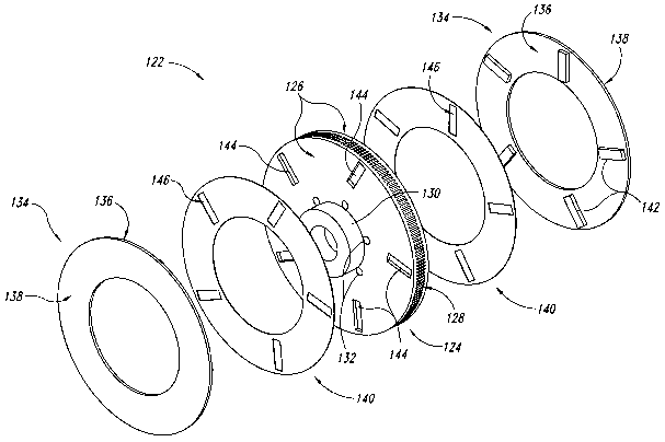
FIG. 1 is an exploded perspective view of one embodiment of the inventive disc
brake
rotor.
FIG. 2 is an enlarged perspective cross-sectional view of a finished inventive
disc brake
rotor assembly of FIG. l, and showing the bonded composite wear plates.
FIG. 3 is a perspective view of a fully assembled disc brake rotor assembly of
FIG. 1.
FIG. 4 is an exploded perspective view of another embodiment of the inventive
disc
-5-
CA 02554567 2006-07-21
WO 2005/069972 PCT/US2005/002090
brake rotor assembly having one or more recessed pockets or cavities in the
rotor for
incorporation of a sensor device, sensor material, heat transfer-enhancing
material, or
combinations thereof.
FIG. 5 is an enlarged perspective cross-sectional view of a finished inventive
disc brake
rotor assembly of FIG. 4, and showing the bonded composite wear plates and
pocket with
incorporated heat transfer-enhancing material (e.g., metallic sodium).
DETAILED DESCRIPTION OF THE INVENTION
Particular embodiments of the present invention provide novel composite disc
brake
rotors comprising flat annular wear plates consisting of or comprising at
least one material
1o selected from the group consisting of: aluminum-based metal matrix
composite (MMC),
comprising a particulate reinforcement; ceramic matrix composite (CMC);
'carbon graphite
foam'; or manganese-bronze having a particulate reinforcement such as, but not
limited to
silicon carbide (e.g., from about 10% to about 35%). The wear plates are
attached to the outer
annual surfaces of a rotor made of a second material (e.g., 356 or 359
aluminum) by fusing of
bonding layers having a melting temperature lower than that of either the
first or the second
materials (e.g., 1100 aluminum), or by use of high-temperature adhesives
(e.g., particularly in
the case of CMC wear plates).
Additional embodiments provide for novel methods of manufacturing of composite
disc
brake rotors.
FIG. 1 shows an exploded perspective view of a composite disc brake rotor
assembly
122 according to one embodiment of the present invention. The disc brake rotor
assembly 122
comprises a center rotor section 124 formed of a first material, and having
generally parallel flat
annular outer surfaces 126. The center rotor 124 is optionally vented or
cooled (e.g., by means
of conventional air channels 128), and is optionally of a one-piece design
with an integral inner
hub (hat) section 130, or of a two-piece design comprising assembled rotor and
a hub elements.
Lug bolt channels 132 are typically present in the 'bolt circle' around the
hat area. Preferably,
the center rotor 122 is formed of, or is substantially comprised of a
conventional aluminum or
-6-
CA 02554567 2006-07-21
WO 2005/069972 PCT/US2005/002090
aluminum alloy, such as 356 (356A) or 359 aluminum, or art-recognized
equivalents thereof.
The disc rotor assembly 122 additionally comprises a pair of generally flat
annular wear
plates 134 cast and formed of a second material, and each having internal 136
and external 138
surfaces. The wear plates 134 are formed of, or are substantially comprised of
a second
material, which is typically a aluminum-based metal matrix composite (MMC),
comprising a
particulate reinforcement, such as silicon carbide. Preferably, the wear
plates 134 are formed of
a particulate reinforced MMC having from about 10% to about 35% by volume
inorganic
materials of a thermal expansion factor less than the alloy. Preferably, the
wear plate material is:
DURALCAN~ (manufactured by Alcan Aluminum Limited), having silicon carbide
particles;
or is a ceramic matrix composite (CMC). Preferably, the wear plates consisting
of or
comprising at least one material selected from the group consisting of:
aluminum-based metal
matrix composite (MMC), comprising a particulate reinforcement; ceramic matrix
composite
(CMC); 'carbon graphite foam'; or manganese-bronze having a particulate
reinforcement such
as, but not limited to silicon carbide (e.g., from about 10% to about 35%).
Preferably, the wear
plates comprise carbon graphite foam.
The center rotor section 124, as well as the annular wear plates 134 are cast
in a mold.
The casting process is performed by any suitable casting process, including
but not limited to die
casting, sand casting, permanent mold casting, squeeze casting, or lost foam
casting. Preferably,
casting is by die-casting. Alternatively, casting of the center rotor section
124, as well as the
2o annular wear plates 134 is by spin-casting, such as that generally
described in U.S. PATENT
5,980,792 to Chamlee (incorporated herein by reference in its entirety). For
example,
aluminum-based metal matrix composite (MMC) comprising a particulate
reinforcement (e.g.,
Duralcan~) containing silicon carbide) is centrifugally spin-casted to cause
and create
functionally beneficial particulate (sic) distributions (gradients). In the
present instance such
casting methods increase particle density at friction surfaces.
Alternatively, aluminum-based alloys, including eutectic and hypereutectic
alloys such
as 380, 388, 398, 413, or others such as 359-356-6061, optionally containing
particulate
reinforcement such as silicon carbide, or aluma oxides, ceramic powders or
blends, can be cast
_7_
CA 02554567 2006-07-21
WO 2005/069972 PCT/US2005/002090
into (e.g., by infiltration casting) a ceramic fiber-based porous 'preform' of
desired specification
using discontinuous alumina-silicate (e.g., Kaowool Saffil Fibers), silicon
carbide, ceramic
powders, or blends of the preceding. Reinforced or non-reinforced aluminum-
based alloys
infiltrate the 'preform' during the casting procedure, making a MMC with
selective
reinforcement. Preferably, casting process is performed by a suitable method,
including, but not
limited to die casting. Alternatively, permanent mold high-vacuum, squeeze
casting, lost foam,
or centrifugal casting (e.g., U.S. 5,980,792) can be employed.
In a particularly embodiments, the aluminum-based alloys (e.g., eutecic,
hypereutectic,
or otherwise), with or without particulate reinforcement are cast into (e.g.,
infiltration casting) a
'preform' of porous 'carbon graphite foam' (with or without particulate
reinforcement, such as
silicon carbide). Carbon graphite foam (developed at Oak Ridge National
Laboratory, USA) has
high thermal conductivity and also acts as super-conductor (see, e.g., U.S.
Patent Nos.:
6,673,328, 6,663,842, 6,656,443, 6,398,994, 6,387,343 and 6,261,485, all of
which are
incorporated by reference herein in their entirety). Preferably the silicon
carbide volume should
be from about 10% to 35% to provide desired friction at wear plate rubbing
surface. Infiltration
of un-reinforced or reinforced alloy into carbon graphite foam 'preform' is
during a suitable
casting procedure including, but not limited to die casting, high-vacuum
permanent mold
casting, squeeze casting, or centrifugal casting. According to the present
invention, carbon
graphite foam can be included in the compositions of at least one of the
central rotor, the wear
2o plates, and the bonding layer (further described below). Preferably, carbon
graphite foam can is
included at least in the composition of the wear plates.
The disc rotor assembly 122 further comprises bonding layers 140, comprising a
metal
alloy having a melting temperature lower than that of either the first or the
second materials (or
alternatively comprising a high-temperature adhesive): During assembly of the
disc brake rotor
assembly 122, the metal alloy bonding layers 140 are fused (melted), between
the internal
surfaces 136 of the friction plates and the outer surfaces 126 of the center
rotor 124. Preferably,
the bonding layer is formed of, or is substantially comprised of 1100
aluminum, or art-
recognized equivalents thereof. The bonding layer can be a layer generated by
spraying
_g_
CA 02554567 2006-07-21
WO 2005/069972 PCT/US2005/002090
methods. For example, flame-spraying can be used to generate a bonding layer
material of 1100
aluminum. Alternatively the bonding layer can be a layer cut (e.g., die-cut)
from a flat sheet.
For example, die-cutting of 1100 aluminum sheet can be used to generate
bonding layer
material. Preferably, the thickness of the bonding layer is from about 0.005
to about 0.020
inches, or from about 0.001 to about 0.20 inches, or from about 0.01 to about
0.10 inches. More
preferably, the thickness of the bonding layer is from about 0.005 to about
0.020 inches.
Preferably, the bonding layer comprises a metal alloy (e.g., 1100 aluminum)
having a melting
temperature lower than that of either the first or the second materials, each
bonding layer being
fused between the internal surfaces of the wear plates and the corresponding
outer surfaces of
to the center rotor section. Preferably, for bonding layers comprising 1100
aluminum and the like,
the bonding layer also comprises an amount of zinc or tin suitable to confer
enhanced bonding
(most likely by lowering the melting temperature of the bonding layer). In
alternative
embodiments, the boding layer is an adhesive (e.g., high-temperature
adhesive). Preferably,
such adhesives are used in combination with, for example, ceramic matrix
composite (CMC)
~ 5 wear plates. Preferably, the bonding layers, whether fused aluminum based
or high-temperature
adhesive comprise one or more additional materials to enhance thermal
conduction. Preferably,
the material comprises 'carbon graphite foam.'
FIG. 2 shows an enlarged perspective cross-sectional view of a finished
inventive disc
brake rotor assembly embodiment 122 of FIG. 1, with the composite ware plates
134 attached to
2o the center rotor section 124 via fused bonding layers 140. Lug bolt
channels 132 are shown in
the 'bolt circle' around the hub (hat) section 130 of the rotor. Venting or
cooling air channels
128 are shown in the center rotor section 124.
FIG. 3 is a perspective view of a fully assembled disc brake rotor assembly
embodiment
122 of FIG. l, with the composite ware plates 134 attached to the center rotor
section 124 via
25 fused bonding layers 140. Lug bolt channels 132 are shown in the 'bolt
circle' around the hub
(hat) section 130 of the rotor.
In preferred embodiments (and with reference to FIG. 1 ) the wear plates 134
further
comprises at least one integral projection 142 projecting from the internal
surface 136 thereof,
-9-
CA 02554567 2006-07-21
WO 2005/069972 PCT/US2005/002090
and the center rotor section 124 further comprises at least one receiver
recess 144 in each of the
outer surfaces 126 of the rotor, wherein the recesses are sized to receive the
projections of the
internal surface 136 of the wear plate 134 positioned adjacent thereto.
Preferably, each bonding
layer 140 further comprises or forms corresponding apertures 146, with the
projections 142 of
the adjacent wear plate extending therethrough. Preferably, each wear plate
comprises from
about 5 to about 10 integral projections 142, and the rotor comprises a
corresponding number of
respective receiver recesses 144. Alternatively, the projections extend from
the outer surfaces of
the center rotor section, through the bonding layer apertures, and into
receiving recesses in the
inner surfaces of the wear plates. Preferably, the projections extend from the
wear plates, and
1 o into receiving recesses on the rotor.
According to particular embodiments of the present invention (and referring to
FIG. 1),
the fused bonding layers 140 adhere to, and enhance bonding of the first and
second materials,
thus providing for enhanced acoustical and thermal transference between the
wear plates 134
and the center rotor 124. According to the present invention, the disc brake
rotor assembly 122
thus has surprisingly improved thermal and acoustic behavior, as well as
improved structural
properties, particularly in the context of the above-described integral
projections. Heat is more
efficiently transferred from the wear plates to the center rotor (preferably
vented rotor center),
and squeals and creep groan are reduced, relative to prior art disc assemblies
lacking the instant
inventive bonding layers. Preferably, carbon graphite foam is included in at
least one of the
wear plates (including the integral projections), and the bonding layers to
further enhance
thermal conductivity, providing substantially more efficient transfer of heat
from the friction
surface, through the wear plate and boding layer to the center rotor, and
providing a
fundamentally improved disc brake system.
According to particular embodiments of the present invention (and referring to
FIG. 1
and FIG. 4), the integral projections 142 are positioned within the receiver
recesses 144 of the
assembled composite disc rotor 122 (or 222) and provide for enhanced
acoustical transference
(as well as thermal transference) between the wear plates 134 and the center
rotor 124.
According to the present invention, at least one of the size, shape,
composition and disposition
-10-
CA 02554567 2006-07-21
WO 2005/069972 PCT/US2005/002090
of the projections serves to 'tune' or optimize the acoustic behavior of the
disc brake rotor
within an operative disc brake assembly. The effect is to sequester both high
and low noise
frequencies to the center rotor. Furthermore, positioning of the integral
projections 142 within
the corresponding receiver recesses 144 serves to enhance mechanical
attachment and resistance
to operative slippage of the wear plates 134 with respect to the rotor surface
126.
In alternate embodiments (and refernng to FIG. 4 and FIG. S), the present
invention
provides for composite rotors further comprising at least one recessed cavity
in an outer surface
thereof, wherein the cavity is sized to hold a sensor device or sensor
material in a position
adjacent, or substantially adjacent to one of the bonding layers. Preferably,
the sensing device or
1o sensing material is one of a heat sensing device or material, respectively;
a speed or motion
sensing device or material, respectively; a vibration sensing device or
material, respectively; a
wear sensing device or material, respectively; a pressure sensing device or
material,
respectively; and a respective combination of two or more thereof. Preferably,
the heat sensing
device or material is a thermal voltaic cell, or a thermal voltaic material,
respectively.
According to the present invention, such recessed cavities may also contain
materials to
enhance heat transfer (e.g., sodium metal or carbon graphite foam-based
materials), galvanic
materials (e.g., zinc), or other electromagnetically-related materials that
may comprise an
integral secondary 'drag brake' system (e.g., electromagnetically based). For
example, such a
drag brake system can be premised on use of graphite foam-based materials (or
other suitable
2o materials) in one or more of the above described elements of the inventive
disc brake system.
The recessed cavities may be positioned in any suitable location within the
surfaces of
the center rotor section. Preferably, the recessed cavities are in a position
of the rotor surface
that is adjacent to a bonding layer. Preferably, for embodiments comprising
integral wear plate
projections 142 (e.g., see FIG. 1), the placement is between the receiver
recesses 144 (see FIG.
1) in the outer surfaces 126 of the rotor, and in positions adjacent to the
bonding layers.
In additional embodiments, the rotor further comprises at least one recessed
cavity in an
outer surface thereof, wherein the cavity is sized to hold a heat transfer-
enhancing material in a
-11-
CA 02554567 2006-07-21
WO 2005/069972 PCT/US2005/002090
position adjacent, or substantially adjacent to one of the bonding layers.
Preferably, the heat
transfer-enhancing material is metallic sodium, or carbon graphite foam.
Preferably, the heat
transfer-enhancing material is consists of, or comprises carbon graphite foam.
FIG. 4 is an exploded perspective view of one alternate embodiment 222 of the
inventive
disc brake rotor assembly having one or more recessed cavities 148 in the
rotor 124 for
incorporation of a sensor device, sensor material, heat transfer-enhancing
material, or
combinations thereof. The cavities 148 are sized to hold a sensor device or
sensor material in a
position just below the outer surface plane 126 of the rotor 124, but
substantially adjacent to one
of the bonding layers 140. The recessed cavities are in a position of the
rotor surface 126 that is
adjacent to a bonding layer 140. Preferably, for embodiments comprising
integral wear plate
projections 142 the placement is between the receiver recesses 144 in the
outer surfaces 126 of
the rotor, and in positions adj acent to the bonding layers 140.
FIG. 5 shows an enlarged perspective cross-sectional view of a finished
inventive disc
brake rotor assembly embodiment 222 of FIG. 4, with the bonded composite wear
plates 134
and recessed cavities 148 filled, or substantially filled with a heat transfer-
enhancing material
(e.g., metallic sodium, or a material consisting of or comprising carbon
graphite foam).
Preferably, the recessed cavities are filled a material consisting of or
comprising carbon graphite
foam, and the material is adjacent to the fused bonding layers 140 in the
finished disc rotor
assembly 222.
Particular embodiments of the present invention thus provide for a composite
disc brake
rotor assembly 122, comprising: a rotor 124 formed of a first material and
having a pair of
annular outer surfaces 126; a pair of annular wear plates 134 formed of a
second material, and
each having internal 136 and external 138 surfaces, the internal surface 138
of each wear plate
being positioned adjacent to a different one of the outer surfaces 126 of the
rotor 124; and
bonding layers 140, comprising a metal alloy having a melting temperature
lower than that of
either the first or the second materials, each bonding layer 140 being fused
between the internal
surface 136 of one of the wear plates and the corresponding outer surface 126
of the rotor.
Alternatively, the bonding layer is a high-temperature adhesive.
-12-
CA 02554567 2006-07-21
WO 2005/069972 PCT/US2005/002090
In preferred embodiments, the wear plates 134 consist of, comprise, or
substantially
comprise a friction material selected from the group consisting of carbon
graphite foam, ceramic
matrix composite ("CMC") having a two- or three-dimensionally interconnected
crystalline
ceramic phase and a non-contiguous metal phase dispersed within the
interconnected ceramic
phase (see, e.g., U.S. Patent Nos. 5,620,791, 5,878,849 and 6,458,466, all of
which incorporated
herein by reference in their entirety), and combinations thereof.
The ceramic phase of the CMC may be a boride, oxide, carbide, nitride,
silicide or
combination thereof. Combinations include, for example, borocarbides,
oxynitrides,
oxycarbides and carbonitrides. The ceramic may include various dopant elements
to provide a
to specifically desired microstructure, or specifically desired mechanical,
physical, or chemical
properties in the resulting composite. The metal phase of the CMC may be a
metal selected
from the Periodic Table Groups 2, 4-11, 13 and 14 and alloys thereof.
In particular embodiments, the CMC is produced by infiltrating a porous
ceramic body
with a metal, thus forming a composite. Such infiltration involves, for
example, forming a
porous ceramic preform prepared from ceramic powder, such as in slip casting
(e.g., a dispersion
of the ceramic powder in a liquid, or as in pressing (e.g., applying pressure
to powder in the
absence of heat), and then infiltrating a liquid metal into the pores of said
preform.
In particular embodiments, the friction material comprises a ceramic-metal
composite
comprised of a metal phase and a ceramic phase dispersed within each other,
wherein the
ceramic phase is present in an amount of at least 20 percent by volume of the
ceramic-metal
composite. In particular embodiments, the braking component is a metal
substrate, such as
aluminum, having laminated thereto a ceramic metal composite of a dense boron
carbide-
aluminum composite having high specific heat and low density.
It will be appreciated that the disc brake rotor 122 may be used in
conjunction with a
variety of art-recognized brake assembly structures.
Methods of Manufacture
A novel and substantially less expensive disc brake manufacturing process is
achieved
-13-
CA 02554567 2006-07-21
WO 2005/069972 PCT/US2005/002090
by employing a fusable bonding layer (or in some instances adhesive boding
layers) to avoid
insert-type second casting procedures of the prior art that involve e.g.,
placement of wear plates
into a rotor mold, followed by traditional casting, in situ, of the center
rotor section.
With reference to FIG. 1, particular embodiments of the present invention
provide novel
methods for manufacturing of composite disc brake rotors, comprising obtaining
a pair of cast
generally annular wear plates 134 formed of a first material and attaching
them to a center rotor
section 124 formed of a second material by means of fused bonding layers 140,
or alternatively
adhesive bonding layers Each cast wear plate has an internal 136 and an
external 138 surface.
The internal surface 136 of each of the wear plates is attached to a different
outer surface 126 of
to the center rotor section 124 by fusing of bonding layers 140 between the
internal surfaces 136 of
the wear plates and the corresponding outer surfaces 126 of the rotor.
In preferred embodiments, the bonding layers 140 comprise a metal alloy (e.g.,
1100
aluminum) having a melting temperature lower than that of either the first or
the second
materials, each bonding layer 140 being fused between the internal surface 136
of one of the
wear plates and the corresponding outer surface 126 of the rotor.
Preferably the first material (wear plates) comprises at least one material
selected from
the group consisting of: aluminum-based metal matrix composite (MMC),
comprising a
particulate reinforcement (e.g., DURALCAN~, containing silicon carbide;
manufactured by
Alcan Aluminum Limited); ceramic matrix composite (CMC); and 'carbon graphite
foam,' and
2o the second material (rotor) is conventional aluminum or aluminum alloy
(e.g., 356 or 359
aluminum).
In particular embodiments, fusing is achieved by casting the rotor in situ in
a mold
already containing the cast wear plates 134 with the bonding layers 140
applied to, or positioned
adjacent to the interior surfaces 136 thereof.
In alternate, preferred embodiments, the bonding layers 140 (e.g. 1100) are
suitably
aligned under pressure between the outer surfaces 126 of a cast center rotor
section and the
corresponding interior surfaces 136 of the cast wear plates prior to, and
during fusing (melting)
-14-
CA 02554567 2006-07-21
WO 2005/069972 PCT/US2005/002090
of the bonding layers. Preferably, fusing is by induction welding (e.g.,
involving attachment of
suitably placed positive and negative electrodes) during manufacturing of the
inventive
composite disc rotors (e.g., using a hydraulic press and induction welding of
components
aligned under pressure). In particular embodiments, alignment of wear plates
onto the center
rotor section (before applying pressure or fusing) is enhanced by means of
alignment pins
embedded and protruding from center section face, which communicate with
alignment holes on
wear plate face. Alternatively, such pins can protrude from the inner face of
the wear plate to
alignment holes of the center section face. Preferably, for high-temperature
adhesive
applications, adhesive is suitably aligned between the outer surfaces of a
cast center rotor section
and corresponding interior surfaces of the cast wear plates prior to, and
during manufacturing of
composite disc rotors using, for example, a hydraulic press.
According to particular aspects of the present invention (and with reference
to FIG. 1),
disc brake rotor problems arising from poor acoustic behavior and poor thermal
conductivity can
be addressed by incorporation of tuning fork-like fingers or projections 142
from the interior
surfaces 136 of the wear plates 134 (or, alternatively, projections from the
center rotor faces to
the receiving recesses in the wear plate inner surfaces). For example, during
assembly of the
finished disc rotor, positioning of the projections 142 within corresponding
receiving recesses
144 of the outer surfaces 126 of the center rotor section 124 provides for
alignment, and
increased thermal and acoustic transference to the center section.
2o Additionally, the use of fused bonding layers 140 enhances bonding between
the wear
plates 134 and the center rotor section 124, and provides for increased
thermal and acoustic
transference to the center section. Preferably, the bonding layers 140 are
formed of a relatively
low melting temperature alloy such as 1100 aluminum, or an equivalent alloy
having a melting
temperature lower than the material of the center rotor 124 or the material of
the wear plates
134. The bonding layers 140 are fused during the manufacturing process, and
act as an adhesive
that improves bonding between the surfaces of the wear plates 134 and center
rotor section 124.
The 1100 aluminum or other low temp alloys can be optionally sprayed on (flame
spray), or die-
cut from .005 to .020 flat sheet. For example, die-cutting of 1100 aluminum
sheet can be used
-15-
CA 02554567 2006-07-21
WO 2005/069972 PCT/US2005/002090
to generate bonding layer material. Preferably, the thickness of the bonding
layer is from about
0.005 to about 0.020 inches, or from about 0.001 to about 0.20 inches, or from
about 0.01 to
about 0.10 inches. More preferably, the thickness of the bonding layer is from
about 0.005 to
about 0.020 inches. Preferably, for bonding layers comprising 1100 aluminum
and the like, the
bonding layer also comprises an amount of zinc or tin suitable to confer
enhanced bonding (most
likely by lowering the melting temperature of the bonding layer). In
alternative embodiments,
the boding layer is an adhesive (e.g., high-temperature adhesive). Preferably,
such adhesives are
used in combination with, for example, ceramic matrix composite (CMC) wear
plates.
Preferably, the bonding layers, whether fused aluminum based or high-
temperature adhesive
1o comprise one or more additional materials to enhance thermal conduction.
Preferably, the
material comprises 'carbon graphite foam.'
In a alternate preferred embodiment (with reference to FIG. 1), a novel method
for
manufacturing a composite disc brake rotors comprises: obtaining a pair of
cast annular wear
plates 134 formed of a first material, and each having internal 136 and
external 138 surfaces;
and attaching the internal surface 136 of each wear plate to a different outer
surface 126 of a
rotor 124 formed of a second material, the attaching involving, at least in
part, fusing of bonding
layers 140 comprising a metal alloy having a melting temperature lower than
that of either the
first or the second materials, each bonding layer 140 being fused between the
internal surface
136 of one of the wear plates and the corresponding outer surface 126 of the
rotor.
2o In some alternate embodiments, fusing is achieved by casting the rotor 124
in situ in a
mold already containing the cast wear plates 134 with the bonding layers 140
applied to, or
positioned adjacent to the interior surfaces 136 thereof.
Preferably, the bonding layers 140 are suitably aligned between the outer
surfaces 126 of
a cast center rotor section and the corresponding interior surfaces 136 of the
cast wear plates
prior to, and during fusing of the bonding layers by inductive welding.
Preferably, the rotor,
bonding layers 140 and wear plates 134 are suitably aligned under pressure
prior to and during
fusing of the bonding layers. Preferably, the pressure is from about 0.5 to
about 15 tons.
Preferably, the pressure is exerted by means of a hydraulic press driving at
least one of two
-16-
CA 02554567 2006-07-21
WO 2005/069972 PCT/US2005/002090
opposed members, each member having a surface conforming to the shape of a
wear plate 134.
In preferred embodiments, the bonding layer 140 is provided in the form of at
least one
of flame-sprayed 1100 aluminum, or die-cut 1100 aluminum sheeting. Preferably,
provision of
the bonding layer is by flame-sprayed 1100 aluminum.
In particular embodiments, the thickness of the bonding layer 140 is from
about 0.005 to
about 0.020 inches, from about 0.001 to about 0.20 inches, or from about 0.01
to about 0.10
inches. Preferably, the thickness of the bonding layer 140 is from about 0.005
to about 0.020
inches.
Bonding layers of high-temperature adhesives are alternately used in place of
fused
to aluminum-based layers. Preferably, such adhesive layers are used in the
context of CMC wear
plate attachment.
Preferably, the second material (for center rotor 124) is at least one of
aluminum and an
aluminum alloy, and the first material (for wear plates 134) consists of, or
comprises a material
selected from the group consisting of: a aluminum-based metal matrix composite
(MMC) with a
particulate reinforcement (e.g., DURALCAN~, containing silicon carbide;
manufactured by
Alcan Aluminum Limited); ceramic matrix composite (CMC); and 'carbon graphite
foam.'
Preferably, the aluminum alloy comprises 356 or 359 aluminum, and the
particulate
reinforcement is silicon carbide. Preferably the wear plates comprise 'carbon
graphite foam.'
According to aspects of the present invention, the fused bonding layer 140
enhances
bonding of the first and second materials, and thus promotes thermal and
acoustical conductivity
between first and second materials. Preferably, the metal alloy of the bonding
layer is one of
1100 aluminum and a variant thereof comprised substantially of 1100 aluminum.
In particular
embodiments, the bonding layer comprises 'carbon graphite foam.'
In preferred embodiments, each wear plate 134 further comprises at least one
integral
projection 142 projecting from the internal surface 136 thereof, and the rotor
124 further
comprises at least one receiver recess 144 in each of the outer surfaces 126
of the rotor sized to
-17-
CA 02554567 2006-07-21
WO 2005/069972 PCT/US2005/002090
receive the projection 142 of the internal surface 136 of the wear plate
positioned adjacent
thereto. Preferably, each bonding layer 140 further comprises at least one
aperture 146, with the
projection 142 of the adjacent wear plate extending therethrough. According to
aspects of the
present invention, at least one of the size, shape and disposition of the
projection is selected to
optimize or tune the acoustic behavior of the rotor within an operative disc
brake assembly.
Alternatively, the projections can be from the center rotor, being received in
the inner surface of
the wear plate.
In alternate preferred embodiments (and with reference to FIG. 4 and FIG. 5),
the rotor
124 further comprises at least one recessed cavity 148 in an outer surface 126
thereof, the cavity
sized to hold a sensor device or sensor material in a position adjacent to one
of the bonding
layers 140. Preferably, the sensing device or sensing material is one of a
heat sensing device or
material, respectively, a speed or motion sensing device or material,
respectively, a vibration
sensing device or material, respectively, a wear sensing device or material,
respectively, a
pressure sensing device or material, respectively, and a respective
combination of two or more
thereof. Preferably, the heat sensing device or material is a thermal voltaic
cell, or a thermal
voltaic material, respectively.
In alternate embodiments, the rotor 124 further comprises a recessed cavity
148 in an
outer surface 126 thereof, wherein the cavity is sized to hold a heat transfer-
enhancing material
in a position adjacent to one of the bonding layers 140. Preferably, the heat
transfer-enhancing
material consists of, or comprises metallic sodium, or a material consisting
of or comprising
carbon graphite foam). Preferably, the recessed cavities are filled a material
consisting of or
comprising carbon graphite foam, and the material is adjacent to the fused
bonding layers 140 in
the finished disc rotor assembly 222.
EXAMPLE 1
(Manufacturing of composite disc rotors using a hydraulic press and induction
welding
of components aligned under pressure)
With reference to FIG. 1 and FIG. 4, a hydraulic press (pressure clamp) with a
minimum
of 15-ton capacity is used in the final assembly of components aligned or
stacked in the
-18-
CA 02554567 2006-07-21
WO 2005/069972 PCT/US2005/002090
following order: wear plate 134 (with interior surface 136 and projections 142
facing the
bonding layer), bonding layer 140, outside surfaces of center rotor section
126, bonding layer
140, and wear plate 134 (with interior surface 136 and projections 142 facing
bonding layer).
Alternatively the bonding layer 140 is flame-sprayed onto the interior surface
136 of the
wear plates prior to alignment of the sprayed wear plates and the center rotor
section.
Optional elements such as sensor devices, sensor materials or heat transfer-
enhancing
materials (e.g., sodium metal or carbon graphite foam) are placed into
conforming recessed
cavities 144 of the center rotor section as the components are aligned and
juxtaposed. The
aligned assembly is then placed onto the lower mandrel of a hydraulic press
having top and
1o bottom mandrels with surfaces conforming to the shape of wear plates 134.
Alternatively, alignment of the components is achieved by sequential stacking
of the
components, in the above-described order, onto the lower conforming mandrel
surface, and then
securing the aligned, stacked assembly between the lower and upper conforming
mandrel
surfaces. Additionally, as described herein above, alignment pins can be used.
Hydraulic pressure is applied to the pressure clamp, whereby the pressurized
conforming
mandrel surfaces further serve to accurately align the upper and lower wear
plates 134. Positive-
and-negative electrodes are attached to the assembly by the use of induction,
and electrical
current flow through the assembly causes the bonding layers 140 (e.g., 1100
aluminum) to fuse
(soften and melt), bonding the aligned components together. Once melting of
the bonding layers
2o is complete, the electrical current is stopped, and the hydraulic pressure
is subsequently released.
The fused disc rotor assembly is subjected to heat treatment, and finished by
final
machining if required.
While various embodiments and preferred embodiments of the present invention
have
been illustrated and described herein, it will be appreciated that various
changes can be made
therein without departing from the spirit and scope of the invention.
-19-