Note: Descriptions are shown in the official language in which they were submitted.
CA 02554785 2006-07-27
WO 2005/086398 PCT/KR2005/000627
-1_
APPARATUS AND METHOD FOR ASSIGNING A RANGING CHANNEL
AND TRANSMITTING AND RECEIVING A RANGING SIGNAL IN AN
OFDM SYSTEM
BACKGROUND OF THE INVENTION
1. Field of the Invention
The present invention relates to an apparatus and a method for allocating
a ranging channel and transmitting and receiving a ranging signal in a
communication system employing an orthogonal frequency division multiplexing
scheme.
2. Descri,~tion of the Related Art
Currently, the 3rd generation (3G) communication system supports a
transmission speed of about 384 Kbps in outdoor environment relatively having
poor channel conditions, and supports a transmission speed of about 2 Mbps in
favorable indoor channel environment. In addition, many researches have been
focused onto the 4~h generation (4G) communication system to provide users
with
various qualities of service (QoS) and transmission speed of about 100 Mbps.
A wireless local area network (WLAN) communication system and a
wireless metropolitan area network (WMAN) communication system generally
support transmission speeds of 20 to 50 Mbps. The WLAN system and the
WMAN system may provide a comparatively high transmission speed, but do not
satisfactorily ensure mobility and various QoSs. Accordingly, research is
being
vigorously pursued to evolve the current communication system into a 4G
communication system in order to simultaneously ensuring both the very high
data rate and mobility.
FIG. 1 is a schematic view of illustrating a broadband wireless access
communication system employing an orthogonal frequency division
multiplexing/orthogonal frequency division multiple access (OFDM/OFDMA)
scheme, wherein it transmits a physical channel signal using a plurality of
sub-
carriers.
Referring to FIG l, the broadband wireless access communication system
has a single cell structure, and includes a base station (BS) 100 and a
plurality of
subscriber stations (SSs) 110, 120, and 130. The transmission and reception of
signals between the BS 100 and the SSs 110, 120, and 130 is according to an
CA 02554785 2006-07-27
WO 2005/086398 PCT/KR2005/000627
-2-
OFDM/OFDMA scheme.
In general, the multiple access method in OFDMA can be achieved by
either one or combination of a time division technique and a frequency
division
technique. The transmitted symbols are carried by a set of subcarrier,
subchannel,
in which each subcarrier can be localized differently in time and frequency. .
FIG 2 schematically illustrates one example of OFDMA frame structure.
Referring to FIG 2, OFDMA symbol numbers are plotted along the abscissa axis
and sub-channel numbers are plotted along the ordinate axis. Further, one
OFDMA frame includes a plurality of OFDMA symbols, e.g., eight OFDMA
symbols.
The physical channel for transmitting ranging signal is addressed herein,
although the purpose of ranging signal will be addressed later. Each OFDMA
frame as constructed above has a plurality of ranging slots, e.g., four
ranging slots,
for transmitting a ranging signal. The plurality of ranging slots form a
ranging
region. Reference numeral 201 designates a ranging region existing in an M-th
frame, and reference numeral 202 designates a ranging region existing in an
(M+1)-th frame. The ranging region is a ranging channel. The ranging channel
includes at least one sub-channel, provided that it exists only during an
uplink
period. The existing OFDMA communication system such as IEEE802.16a has
been designed to acquire a frequency diversity gain by distributing all sub-
carriers
over an entire frequency band.
When a time division duplexing (TDD) technique is applied to the
OFDMA communication system, a subscriber station (SS) is required to perform
a ranging operation in order to synchronize in time between multiple
subscriber
stations (SS's) on the transmitting side and a BS on the receiving side, and
to
adjust reception power of the BS. This requirement in TDD system can be met by
transmitting ranging signal to BS from SS.
The ranging operation is divided into initial ranging and maintenance
ranging. The maintenance ranging is in turn further classified into periodic
ranging and bandwidth request ranging.
Hereinafter, a description will be given for a ranging operation that is
commonly used in a conventional broadband wireless communication system.
CA 02554785 2006-07-27
WO 2005/086398 PCT/KR2005/000627
-3-
First, the initial ranging is performed by SS who wants to acquire timing
sync and transmit power setting with a BS. For example, the operational
procedure is as follow in IEEE802.16a/e TDD mode. The SS is powered on and
start to synchronize in down link by signal processing of preamble and pilot.
After downlink synchronization is completed, the SS starts to receive control
message such as a DL MAP message, an LTL-MAP message and an UCD
message. Thereafter, the SS performs the initial ranging with the BS, in order
to
adjust the time offset and the transmit power.
The periodic ranging is operation by the SS already having adjusted the
time offset and the transmit power through the initial ranging with the BS.
The SS
periodically performs periodic ranging, in order to track time offset with the
BS
and a channel state, etc. The SS performs the periodic ranging using ranging
codes assigned by the BS.
The bandwidth request ranging is operation by the SS, already having
adjusted the time offset and the transmit power through the initial ranging in
order
to request bandwidth that can actually be used for communication with the BS.
Ranging sub-channels and ranging codes are needed to generate ranging
signal..This has been already described with reference to FIG 2. The BS
predefines ranging codes of respective ranging operation. More specifically,
the
ranging codes are assigned as described below.
The ranging codes are usually generated by segmenting a sequence
having a predetermined length by a predetermined unit. As an example of a
sequence for generating ranging codes, a pseudorandom noise (PN) sequence
having a length of 32767 bits may be used. The PN sequence is segmented into
PN codes through the ranging channel having a certain length (the length of
106
bits, for example) to construct ranging codes by the PN codes.
Supposing that N ranging codes are assigned for initial ranging, M
ranging codes are assigned for periodic ranging and L ranging codes are
assigned
for bandwidth request ranging. The assigned ranging codes are then transmitted
to
SSs through a DL-MAP message. The SSs use the ranging codes included in the
DL MAP message suitably to their purposes to perform ranging procedures.
However, the SS randomly selects ranging slots and ranging codes for the
initial ranging, the periodic ranging, and the bandwidth request ranging in
the
CA 02554785 2006-07-27
WO 2005/086398 PCT/KR2005/000627
-4-
OFDMA communication system. Consequently, a collision between either
different ranging codes in the same time slot or same ranging codes in the
same
time slot frequently occurs. If the collision between ranging codes occurs, it
is
quite probable that a BS fails in recognizing the ranging code of the SS. This
is
one cause for delaying access between the BS and the SS. Consequently, the
access delay deteriorates performance of the OFDMA communication system.
In performing the periodic ranging and the bandwidth request ranging,
the OFDMA scheme utilizes a random access method in which a random ranging
code is transmitted through a random ranging slot. Therefore, it is likely
that the
ranging codes collide with each other. If the collision between ranging codes
occurs, a re-access process is tried after exponential random back-off in
time. In
this case, access delay time becomes longer and system access delay time
cannot
be guaranteed. More specifically, the higher the probability of ranging code
collision is, the longer an access delay time becomes. Accordingly, when SSs
attempt wireless random access to a BS, the following points must be taken
into
consideration: First, ranging performed by the SS can be regarded as
contention
ranging because each SS randomly selects ranging codes and ranging time slots.
Here, for contention ranging the same transmission time slot, the same
frequency,
and the same code may be used in common by a plurality of SSs. As a result,
access time delay is caused by an intercollision between ranging codes during
initial access or handover. Even if only one ranging signal is transmitted on
a
ranging frequency band, the BS may fail to detect the signal if the signal
strength
is not enough. Second, because each cell in cellular network uses different
frequency band for ranging (frequency positions of ranging sub-carriers),
inter-
cell interference between a ranging signal and a data signal is incurred. For
example, because an SS A located in a cell under the control of a BS A does
not
use the same ranging transmission frequency as that of an SS B located in a
cell
under the control of a BS A, a ranging signal of the SS A interferes with the
BS B.
Also, a ranging signal of the SS B interferes with the BS A. If the intensity
of the
ranging signal transmitted by the SS A excessively interferes with the BS B
(so-
called near-fax problem), the transmission power adjustment of the SS A must
be
limitative. Therefore, it takes considerable time for the SS to adjust the
ranging
signal to an intensity level at which the BS A can receive the ranging signal,
with
the result that initial access time of the system becomes longer. Third, the
PN
code used as a ranging code does not ensure that an intercode cross-
correlation
characteristic has orthogonality. That is, when the PN codes share the
transmission time slot and the transmission frequency with each other, code
interference is incurred for lack of orthogonality between the ranging codes,
CA 02554785 2006-07-27
WO 2005/086398 PCT/KR2005/000627
-5-
which results in deterioration of ranging performance. Fourth, because
frequencies for ranging (frequency positions of ranging sub-carriers) are
randomly distributed over the entire available band, a code correlation
characteristic between the ranging codes is not maintained due to fluctuation
of
the channel frequency response. This may cause increased code interference.
That
is, when a wireless access channel is a multipath channel, the code
correlation
characteristic is deteriorated because the channel shows frequency
selectivity, that
is, its channel response varies with frequency. The increased code
interference
arisen by the reasons mentioned above results in ranging failure of the SSs.
SUMMARY OF THE INVENTION
Accordingly, the present invention has been designed to solve the above
and other problems occurring in the prior art. An object of the present
invention is
to provide an apparatus and a method for assigning a cell shared frequency
band
to a ranging channel in order to minimize signal interference with data.
It is another object of the present invention to provide a ranging channel
structure that permits a collision between ranging signals, but prevents
interference between a ranging signal and a data signal.
It is still another object of the present invention to provide an apparatus
and a method for receiving a ranging signal such that a collision between
ranging
signals is allowed, but interference between a ranging signal and a data
signal is
prevented.
It is still yet another object of the present invention to provide an
apparatus and a method for transmitting a ranging signal such that a collision
between ranging signals is allowed, but interference between a ranging signal
and
a data signal is prevented.
It is still yet another object of the present invention to provide an
apparatus and a method for receiving a ranging channel for the acquisition of
uplink synchronization, such that signal interference can be minimized.
It is still yet another object of the present invention to provide an
apparatus and a method for transmitting and receiving a ranging signal such
that
an initial access time of a system can be minimized.
CA 02554785 2006-07-27
WO 2005/086398 PCT/KR2005/000627
-6-
In order to accomplish the above and other objects, there is provided a
method for assigning a ranging channel in an OFDM/OFDMA communication
system in which an SS attempts ranging with a BS. The method includes the
steps
of: determining at least two ranging bands each of which uses a frequency band
fixed regardless of BSs within the entire frequency band; and assigning no
ranging channel or assigning one or more ranging channels to each of uplink
frames by means of at least the two ranging bands, wherein the fixed frequency
band is a set of one sub-carrier or two or more sub-carriers which
consecutively
exist on a frequency axis.
In accordance with another aspect of the present invention, there is
provided a method for transmitting a ranging signal in an OFDM/OFDMA
communication system. The method includes the steps of: determining an uplink
frame where ranging is to be attempted; and transmitting ranging codes
corresponding to a desired ranging class through one or more ranging bands
which constructs a ranging channel assigned for the determined uplink frame,
wherein a frequency band fixed regardless of BSs within the entire frequency
band is used as the ranging band, and the fixed frequency band is a set of one
sub-
carrier or two or more sub-carriers which consecutively exist on a frequency
axis.
In accordance with still another aspect of the present invention, there is
provided an apparatus for transmitting a ranging signal in an OFDM/OFDMA
communication system. The apparatus includes: a ranging band assigning unit
for
inputting ranging codes corresponding to a desired ranging class and
outputting
the ranging codes at one or more ranging bands which construct a ranging
channel assigned for an uplink frame where ranging is to be attempted; and an
inverse fast Fourier transform unit for transforming the ranging codes output
at
the one or more ranging bands into time domain ranging bands, wherein a
frequency band fixed regardless of BSs within the entire frequency band is
used
as the ranging band, and the fixed frequency band is a set of one sub-carrier
or
two or more sub-carriers which consecutively exist on a frequency axis.
In accordance with still yet another aspect of the present invention, there
is provided a method for receiving a ranging signal in an OFDM/OFDMS
communication system. The method includes the steps of: receiving ranging
codes through one or more ranging bands which construct a ranging channel
assigned uplink frame by uplink frame; and performing ranging corresponding to
the ranging codes, wherein a frequency band fixed regardless of BSs within the
entire frequency band is used as the ranging band, and the fixed frequency
band is
CA 02554785 2006-07-27
WO 2005/086398 PCT/KR2005/000627
-7_
a set of one sub-carrier or two or more sub-carriers which consecutively exist
on a
frequency axis.
In accordance with still yet another aspect of the present invention, there
is provided an apparatus for receiving a ranging signal in an OFDM/OFDMS
communication system. The apparatus includes: a ranging band separating unit
for separating one or more ranging bands, which construct a ranging channel
assigned uplink frame by uplink frame, from a received ranging signal and
extracting sample values from the separated ranging band; and a ranging code
detecting unit for detecting ranging codes by the extracted sample values,
wherein
a frequency band fixed regardless of BSs within the entire frequency band is
used
as the ranging band, and the fixed frequency band is a set of one sub-carrier
or
two or more sub-carriers which consecutively exist on a frequency axis.
BRIEF DESCRIPTION OF THE DRAWINGS
The above and other objects, features, and advantages of the present
invention will be more apparent from the following detailed description taken
in
conjunction with the accompanying drawings, in which:
FIG 1 is a schematic view illustrating a broadband wireless access
communication system utilizing an OFDM/OFDMA scheme;
FIG. 2 is a diagram illustrating a frame structure of a broadband wireless
access communication system utilizing an OFDM/OFDMA scheme in a time-
frequency domain;
FIGS. 3A to 3C are diagrams illustrating a ranging channel structure of a
TDD broadband wireless access communication system utilizing an
OFDMIOFDMA scheme in accordance with a preferred embodiment of the
present invention;
FIG. 4 is a block diagram illustrating a ranging receiver of a broadband
wireless access communication system utilizing an OFDM/OFDMA scheme in
accordance with a preferred embodiment of the present invention;
FIG. 5 is a block diagram illustrating a detailed construction of the
ranging code multiplier illustrated in FIG. 4;
FIG. 6 is a block diagram illustrating a detailed construction of the sync
detector illustrated in FIG. 4;
FIG. 7 is a flowchart illustrating a control flow according to the operation
of the sync comparator illustrated in FIG. 4;
FIG 8 is a block diagram illustrating a bandwidth request ranging
receiver of a broadband wireless access communication system utilizing an
CA 02554785 2006-07-27
WO 2005/086398 PCT/KR2005/000627
_$_
OFDM/OFDMA scheme in accordance with a preferred embodiment of the
present invention;
FIG 9 is a flowchart illustrating a control flow according to the operation
of the ranging code comparator illustrated in FIG. 8;
FIG 10 is a block diagram illustrating a ranging transmitter of a
broadband wireless access communication system utilizing an OFDM/OFDMA
scheme in accordance with a preferred embodiment of the present invention; and
FIG 11 is a flowchart illustrating a control flow carried out by a ranging
receiver in a broadband wireless access communication system utilizing an
OFDM/OFDMA scheme in accordance with a preferred embodiment of the
present invention.
DETAILED DESCRIPTION OF THE PREFERRED EMBODIMENT
Preferred embodiments of the present invention will be described in
detail herein below with reference to the accompanying drawings. In the
following description, a detailed description of known functions and
configurations incorporated herein will be omitted when it may make the
subject
matter of the present invention rather unclear.
The present invention provides a ranging channel structure, which
improves reception performance of a ranging signal in order to minimize
wireless
access delay time in a communication system utilizing an OFDMA scheme, i.e.,
an OFDMA communication system.
Items proposed in accordance with preferred embodiments of the present
invention to be described later will be summarized herein below.
First, in a conventional OFDMA communication system, signal
interference between a ranging signal and a data signal occurs among cells
because frequency positions of ranging sub-carriers are different cell by
cell. The
present invention proposes a cell shared ranging frequency band in order to
minimize the signal interference with data. This causes an SS A of a BS A and
an
SS B of a BS B to use a shared ranging frequency band, such that a collision
between signals of neighbor cells may be allowed, but signal interference
between a ranging signal and a data signal does not occur.
Secondly, because frequencies for ranging, i.e., frequency positions of
ranging sub~carriers, are distributed similarly to random distribution over
the
CA 02554785 2006-07-27
WO 2005/086398 PCT/KR2005/000627
-9-
entire available band, a code correlation characteristic between ranging codes
is
not maintained and code interference is increased. Accordingly, the present
invention proposes a scheme of assigning a ranging frequency band such that
effective ranging performance is presented even in a channel that shows
frequency selectivity, that is, a channel response of which seriously varies
with
frequency, a channel diversity effect can be obtained, and the probability of
false
code alarm can be reduced.
Hereinafter, a description will be given for a ranging channel structure
newly proposed by the present invention and its operating scheme with
reference
to the accompanying drawings. Although the ranging channel structure and its
operating scheme will be described below with respect to a TDD system; it is
obvious to the skilled in the art that they can be similarly applied to an FDD
system.
A frame used in the TDD system has a structure in which a downlink
frame and an uplink frame are alternately used on a time axis. Also, the
number of
ranging channels that are assigned only to an uplink frame may be variably
adjusted every frame according to BSs.
The assignment of the ranging channel, frame by frame, is accomplished
by an UL-MAP message broadcasted from the BS. Accordingly, allocation
information of primary ranging channel and secondary ranging channel is
included in the LTL-MAP message. In particular, the secondary channel is a
ranging channel that can be additionally used, aside from the primary ranging
channel, according to a specific situation of the cell.
In assigning the ranging channel, the BS may additionally assign the
secondary ranging channel after the assignment of the primary ranging channel.
An SS desiring to attempt ranging during an uplink frame period to which the
BS
does not give permission for the use of the secondary ranging channel must
transmit ranging codes using only the primary ranging channel. Otherwise, an
SS
desiring to attempt ranging during an uplink frame period to which the BS
gives
permission for the use of the secondary ranging channel selects one of the
primary and secondary ranging channels and then transmits ranging codes
through the selected ranging channel. However, the BS may not assign the
ranging channel to a specific uplink frame. Of course, when the BS does not
give
permission for the use of both the primary and secondary ranging channels to a
specific uplink frame, no SS can transmit ranging codes through the uplink
frame.
CA 02554785 2006-07-27
WO 2005/086398 PCT/KR2005/000627
- 10-
FIGs. 3A to 3C are diagrams illustrating a ranging channel structure
newly proposed according to an embodiment of the present invention, on the
basis of a TDD system.
In FIG 3A, ranging channel configuration in a uplink/downlink frame
structure used in the TDD system is plotted in a frequency-time domain. More
specifically, only a primary ranging channel is assigned to a K-th uplink
frame
and a (K+3)-th uplink frame, but primary and secondary ranging channels are
assigned to a (K+1)-th uplink frame. Therefore, an SS accessing the (K+3)-th
uplink frame can transmit ranging codes only through the primary ranging
channel.
In contrast with this, an SS accessing the (K+1)-th uplink frame can
select one of the primary and secondary ranging frame, and then transmit
ranging
codes through the selected ranging channel.
Each of the primary and secondary ranging channels includes a set of one
sub-carrier or two or more consecutive sub-carriers in a frequency domain
(ranging band) 301, 303, 305, and 307. Although FIG 3A illustrates only an
example in which one ranging channel includes two ranging bands (primary and
secondary ranging bands), it is obvious to the skilled in the art that the
ranging
channel mayinclude more ranging bands.
Herein, ranging bands 301 and 303 of the primary ranging channel
(primary ranging bands) within one uplink frame are arranged at a certain
distance on a frequency axis. Ranging bands 305 and 307 of the secondary
ranging channel (secondary ranging bands) within one uplink frame are also
arranged at a constant distance on the frequency axis. The primary ranging
bands
301 and 303 and the secondary ranging bands 305 and 307 are alternately
arranged within an uplink frame to which both the primary and secondary
ranging
channels are assigned. This can be easily seen from the structure of the (K+1)-
th
uplink frame. However, it is also possible to arrange the ranging bands such
that
the primary ranging bands consecutively exist and the secondary ranging bands
consecutively exist.
Each of the primary ranging bands assigned to the (K+1)-th and (K+3)-th
frames exists in the same frequency region. This is the same to the secondary
ranging bands. That is, the ranging bands use the same frequency region even
if
they are assigned to different uplink frames.
CA 02554785 2006-07-27
WO 2005/086398 PCT/KR2005/000627
-11-
However, no ranging channel is assigned to a (K+2)-th uplink frame.
Consequently, an SS desiring to attempt ranging during the (K+2)-th uplink
frame
period cannot transmit ranging codes.
FIG. 3B illustrates an enlarged ranging channel structure in the (K+1)-th
uplink frame of FIG 3A, to which both the primary and secondary ranging
channels are assigned. Referring to FIG. 3B, each of the primary and secondary
ranging bands 301, 303, 305, and 307 include three OFDM symbols. However,
each ranging band may consist of two OFDM symbols. When each ranging band
includes two OFDM symbols, the two OFDM symbols correspond to a first
symbol and a second symbol of the relevant uplink frame.
FIG 3C illustrates an example in which initial ranging /handover ranging
and bandwidth request ranging/periodic ranging are arranged in the ranging
bands
301, 303, 305, and 307 of the assigned ranging channels. Referring to FIG. 3C,
some of sub-carriers included in the ranging band are used for initial ranging
(initial RNG) and handover ranging (HO RNG), and the other sub-carriers are
used for bandwidth request ranging (BR RNG) and periodic ranging (PR RNG).
Two symbols are used for the initial ranging (initial RNG) and the handover
ranging (HO RNG). The two symbols use the same frequency region, but they are
distinguished by ranging codes. However, only one symbol is used for the
bandwidth request ranging (BR RNG) and the periodic ranging (PR RNG). Two
symbols existing in the same ranging band use the same frequency region, but
they are distinguished by different ranging codes.
Therefore, for the initial ranging and the handover ranging, an SS has
only one opportunity to attempt ranging over a period of the two symbols.
However, an SS can choose one of two opportunities and attempt ranging in case
of the bandwidth request ranging and the periodic ranging. Each of the ranging
bands include K sub-carriers. However, because each SS uses two ranging bands,
it can use 2K sub-carriers. Accordingly, the length of the ranging code is 2K.
In order that a BS assigns ranging bands of the primary and secondary
ranging channels as described above, several things must be taken into
consideration. One thing is that the primary and secondary ranging bands must
use a fixed frequency band assigned regardless of BSs. However, an isolated
BS,
which is located far from other BSs and is insensitive to signal interference,
can
divide a frequency band and use the divided frequency bands. Such a method of
assigning a frequency band is intended to prevent a ranging signal between
cells
CA 02554785 2006-07-27
WO 2005/086398 PCT/KR2005/000627
- 12-
adjacent to each other from acting as interference with data signal of a
neighbor
BS.
Hereinafter, a detailed description will be additionally given for a ranging
channel used in the present invention and a relation between ranging bands
included in the ranging channel.
The ranging channel may include N ranging bands. Here, N is an
involution of 2. That is, N = 1, 2, 4, 8, 16, ..., K. If the number of sub-
carriers is
K, K sub-carriers are assigned to one ranging band when N = 1, K/2 sub-
carriers
are assigned to one ranging band when K = 2, K/4 sub-carriers are assigned to
one ranging band when K = 4, and one sub-carrier is assigned to one ranging
band when K = K.
The ranging channel used in the embodiment of the present invention is
an available frequency band which an SS uses for attempted ranging, and the
ranging band as a component constituting the ranging channel is an available
frequency band of consecutive ranging sub-carriers.
Hereinafter, a structure of a receiver provided at a BS in the embodiment
of the present invention and its operation based on this structure will be
described
in detail with reference to the accompanying drawings. The receiver is divided
into a receiver for receiving ranging codes to acquire uplink sync and a
receiver
for detecting bandwidth request ranging. Accordingly, the following
description
will be given separately for the two receivers.
In the receiver for receiving ranging codes to acquire uplink sync, the
ranging codes are transmitted by an SS, and a BS receives the transmitted
ranging
codes to acquire uplink sync. The receiver to be described below may be
provided
at the BS.
FIG. 4 illustrates a receiver for acquiring uplink sync by a ranging signal
in accordance with an embodiment of the present invention. More specifically,
the
receiver illustrated in FIG 4 includes a serial/parallel (S/P) converting unit
401,
an FFT unit 403, an initial ranging band separating unit 405, a plurality of
ranging
code multiplying units 407a and 407b, a plurality of sync detecting units 409a
and
409b, and a sync comparing unit 411.
Referring to FIG. 4, a ranging signal received from an SS is supplied to
CA 02554785 2006-07-27
WO 2005/086398 PCT/KR2005/000627
-13-
the S/P converting unit 401. The S/P converting unit 401 converts the ranging
signal into parallel signals and outputs the converted parallel signals. The
parallel
ranging signals are supplied to the FFT unit 403. The FFT unit 403 performs
fast
Fourier transform to the parallel ranging signals to transform time-domain
ranging signals into frequency-domain ranging signals and outputs the
frequency-
domain ranging signals. The parallel ranging signals transformed into the
frequency-domain ranging signals are supplied to the initial ranging band
separating unit 405. The initial ranging band separating unit 405 separates
ranging
bands assigned for initial ranging from the respective frequency-domain
parallel
ranging signals. The initial ranging band separating unit 405 also extracts
only
sample values from the separated ranging bands and outputs the extracted
sample
values. The sample values are supplied to correspondent ranging code
multiplying
units 407a and 407b.
The ranging code multiplying units 407a and 407b multiply the supplied
sample values by predetermined ranging codes and output the sample values
multiplied by the predetermined ranging codes. The signals output from the
ranging code multiplying units 407a and 407b and supplied to correspondent
sync
detecting units 409a and 409b exhibit a frequency characteristic of a channel.
The
sync detecting units 409a and 409b take a correlation between input signals
and
predetermined phase adjustment values, and output a phase adjustment value
having a maximum correlation value as a measured sync value Otl and Ot2. The
measured sync values Otl and Ot2 output from the respective sync detecting
units
409a and 409b are supplied to the sync comparing unit 411. The sync comparing
unit 411 compares the measured sync values Ot~ and OtZ with each other to
output
a maximum value as a final measured sync value.
FIG. 5 illustrates an example using the ranging code multiplying units
407a and 407b as illustrated in FIG. 4. Referring to FIG. 5, a plurality of
output
signals supplied from the initial ranging band separating unit 405 are input
to
corresponding multipliers, respectively. An initial ranging code generator 501
generates initial ranging codes, which are managed by a BS, and provides the
initial ranging codes as another input to the corresponding multipliers. The
multipliers multiply the signals supplied from the initial ranging band
separating
unit 405 by the initial ranging codes provided from the initial ranging code
generator 501 and output the resultant signals. That is, the multipliers
perform
complex multiplication for the frequency-domain signals output from the
initial
ranging band separating unit 405. For an output signal having a specific
initial
ranging code component from among the output signals, the specific initial
CA 02554785 2006-07-27
WO 2005/086398 PCT/KR2005/000627
- I4-
ranging code component is eliminated.
FIG. 6 illustrates an example using the sync detecting units 409a and
409b, which are illustrated in FIG. 4. Referring to FIG 6, output signals from
the
ranging code multiplying units 407a and 407b are input to corresponding
multipliers. For convenience of explanation, it is assumed that, of the
signals
output from the initial ranging multiplying units 407a and 407b, the output
signal
from the initial ranging multiplying unit 407a is input to the sync detecting
unit
409a. However, it is obvious to the skilled in the art that an operation to be
described below can be similarly applied to a case where the output signal
from
the initial ranging multiplying unit 407b is input to the sync detecting unit
409b.
Each of the multipliers implements complex multiplication of an output
signal input to itself and specific phase information. This may correspond to
an
operation for taking a correlation between the output signal and the specific
phase
information provided according to sub-carrier indexes. The specific phase
information can be defined using Equation (1):
exp( ~2'~k~t ) ......................................... ( 1 )
N
where, N: output sample size of IFFT unit or FFT unit;
k: sub-carrier index of sample output from initial ranging band
separating unit;
Ot: arbitrary integer value subjected to brutal force in order to estimate
actual timing offset of ranging signal (-N < ~t < N).
The specific phase information input to the multipliers is generated
according to sub-carrier indexes of the output sample from the ranging code
multiplying unit 407a. The sub-carrier index is determined in a range of k to
k+K-
1. Here, K is the number of sub-carriers assigned to the initial ranging band.
The specific phase information generated according to sub-carrier indexes
has been defined as above in Equation (1). However, in order to generate the
specific phase information, a phase adjustment value generating unit 601
successively generates all predetermined phase adjustment values. That is, the
phase adjustment values are applied to Equation ( 1 ) and output as specific
phase
information according to sub-carrier indexes. The specific phase information
is
then input to a multiplier of the above described multipliers.
CA 02554785 2006-07-27
WO 2005/086398 PCT/KR2005/000627
-15-
The phase-adjusted signals from the respective multipliers are input to an
adder 603. The adder 603 adds the phase-adjusted signals to each other to
output
one phase-adjusted signal. The phase-adjusted signal output from the adder 603
has a peak value when the phase adjustment value ~t is equal to timing offset
of
the ranging signal.
The phase-adjusted signal form the adder 603 is input to a comparator
605. The comparator 605 compares the phase-adjusted signal with a
predetermined threshold value thr. As a result of comparison, if the phase-
adjusted signal is equal to or larger than the predetermined threshold value
thr, the
comparator 605 transfers the phase-adjusted signal to a buffer 607. The phase
adjustment value fit, which has been generated by the phase adjustment value
generating unit 601 in order to obtain the phase-adjusted signal, is supplied
together to the buffer 607. However, if the phase-adjusted signal is less than
the
predetermined threshold value thr, the comparator 605 eliminates the phase-
adjusted signal.
The above-described operation is implemented for all phase adjustment
values, which can be generated from the phase adjustment value generating unit
601. Therfore, the phase-adjusted signals output from the comparator 605 are
stored together with the corresponding adjustment value in the buffer 607.
When the above-described operation is completed for all the phase
adjustment values, the buffer 607 outputs the phase-adjusted signals and the
corresponding phase adjustment values stored therein to an index detector 609.
The index detector 609 detects a phase-adjusted signal having a maximum value
of the phase-adjusted signals, and checks a phase adjustment value
corresponding
to the detected phase-adjusted signal to output the phase adjustment value as
a
measured sync value.
FIG. 7 illustrates a control flow according to the operation of the sync
comparing unit 411 illustrated in FIG. 4. The sync comparing unit 411
determines
a final measured sync value using measured sync values provided from the sync
detecting units to acquire uplink sync.
Referring to FIG. 7, the sync comparing unit 411 inputs measured sync
values Ot~ and Ot2 from the plurality of sync detecting units 409a and 409b in
step
710. In step 712, the sync comparing unit 411 determines if the absolute value
IOtI, Ot21 of a difference between the measured sync values is less than a
CA 02554785 2006-07-27
WO 2005/086398 PCT/KR2005/000627
-16-
predetermined threshold value (allowed time offset). If this condition is
satisfied,
the sync comparing unit 411 proceeds to step 14. However, if the condition is
not satisfied, the sync comparing unit 411 concludes sync estimation to be
failed
and terminates the initial ranging operation.
In step 714, the sync comparing unit 411 calculates a final measured sync
value using Equation (2) and outputs the final measured sync value.
4t1 + Ot2
~t = 2 ...........................................(2)
The final measured sync value output by Equation (2) is a timing offset.
The obtained timing offset is included in an RNG-RSP message and is
broadcasted. Thereafter, the initial ranging operation comes to an end.
The above-described operation for adjusting timing offset of initial
ranging is identical to those for adjusting timing offset of handover ranging
and
periodic ranging. However, for handover ranging, the initial ranging band
separating unit 405 and the initial ranging code multiplying units 407a and
407b
in FIG. 4 must be replaced by a handover ranging band separating unit and
handover ranging code multiplying units, respectively. Also, the initial
ranging
code generator 501 in FIG. 5 must be replaced by a handover ranging code
generator.
Similarly, for periodic ranging, the initial ranging band separating unit
405 and the initial ranging code multiplying units 407a and 407b in FIG 4 must
be replaced by a periodic ranging band separating unit and periodic ranging
code
multiplying units, respectively. Also, the initial ranging code generator SO1
in FIG.
must be replaced by a periodic ranging code generator.
FIG. 8 illustrates a receiver for detecting bandwidth request ranging in
accordance with an embodiment of the present invention. The receiver in FIG 8
includes an S/P converting unit 801, an FFT unit 803, a bandwidth request
ranging band separating unit 805, a plurality of ranging code correlating
units
807a and 807b, a plurality of peak detecting units 809a and 809b, and a
ranging
code comparing unit 811.
Referring to FIG. 8, a bandwidth request ranging signal received from an
SS is supplied to the S/P converting unit 801. The S/P converting unit 801
CA 02554785 2006-07-27
WO 2005/086398 PCT/KR2005/000627
- 17-
converts the bandwidth request ranging signal into parallel signals and
outputs the
converted parallel signals. The parallel bandwidth request ranging signals are
supplied to the FFT unit 803. The FFT unit 803 performs fast Fourier transform
to
the parallel bandwidth request ranging signals to transform time-domain
bandwidth request ranging signals into frequency-domain bandwidth request
ranging signals and outputs the frequency-domain bandwidth request ranging
signals. The parallel bandwidth request ranging signals transformed into the
frequency-domain bandwidth request ranging signals are supplied to the
bandwidth request ranging band separating unit 805.
The bandwidth request ranging band separating unit 805 separates
ranging bands assigned for bandwidth request ranging from the respective
parallel
bandwidth request ranging signals. The bandwidth request ranging band
separating unit 805 also extracts only sample values from the separated
ranging
bands and outputs the extracted sample values. The sample values are supplied
to
correspondent ranging code correlating units 807a and 807b.
Each of the ranging code correlating units 807a and 807b multiplies the
supplied sample values by predetermined bandwidth request ranging codes, adds
the resultant values to each other, and then outputs correlation values
according to
the sample values. That is, because the ranging code correlating units 807a
and
807b evaluates correlations between all of the allowed bandwidth request
ranging
codes and the received signal, the output values from the ranging code
correlating
units 807a and 807b are correlation values between the respective bandwidth
request ranging codes and the received signal. Therefore, the correlation
values
output from the ranging code correlating units 807a and 807b are determined by
if
the received bandwidth request ranging code corresponds to an already-known
ranging code. For example, if the received bandwidth request ranging code
corresponds to the already-known ranging code, autocorrelation between the two
codes is high and a correlation value also has a peak value. However, if the
received bandwidth request ranging code does not correspond to the already-
known ranging code, autocorrelation between the two codes is low and a
correlation value does not have a peak value.
The correlation values from the ranging code correlating unit 870a and
807b are supplied to corresponding peak detecting units 809a and 809b. The
peak
detecting units 809a and 809b detect indexes of the ranging codes
corresponding
to the correlation values, which exceed predetermined threshold values, from
among the input correlation values. The peak detecting units 809a and 809b
also
CA 02554785 2006-07-27
WO 2005/086398 PCT/KR2005/000627
-18-
supply the detected indexes of the ranging codes to the ranging code comparing
unit 811.
The ranging code comparing unit 811 checks if identical ranging codes
are detected from plural bandwidth request ranging bands. If identical ranging
codes are detected, the ranging code comparing unit 811 replies to the SS that
bandwidth request ranging is confirmed. However, if identical ranging codes
are
not detected, the ranging code comparing unit 811 does not reply to the SS
that
bandwidth request ranging is confirmed.
FIG 9 illustrates a control flow for the ranging code comparing unit 811
illustrated in FIG. 8. That is, the ranging code comparing unit 811 determines
success or failure in confirming bandwidth request ranging by the ranging
codes
provided from the peak detecting units.
Referring to FIG 9, in step 910, the ranging code comparing unit 811 is
provided with primary ranging code index determined as a peak value in primary
bandwidth request band and secondary ranging code index determined as a peak
value in secondary bandwidth request ranging band from the peak detecting
units
809a and 809b. The ranging code comparing unit 811 then proceeds to step 912
to
check if the primary and secondary ranging code indexes correspond to each
other.
If the primary ranging code index is equal to the secondary ranging code
index,
the ranging code comparing unit 811 proceeds to step 914, concluding that is
has
successfully confirmed bandwidth request ranging. However, if the primary
ranging code index is not equal to the secondary ranging code index, the
ranging
code comparing unit 811 proceeds to step 916, concluding that it has failed to
confirm bandwidth request ranging.
Once success or failure in confirming bandwidth request ranging is
determined, the ranging code comparing unit 811 proceeds to step 918 to
determine if a bandwidth request band to be searched exists. If the bandwidth
request band to be searched exists, the ranging code comparing unit 811
returns to
step 912 to repeat the above-mentioned operations. Otherwise, if the bandwidth
request band to be searched does not exist, the ranging code comparing unit
811
terminates the operations for confirming bandwidth request ranging.
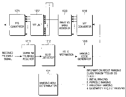
FIG 10 illustrates a transmitter in accordance with an embodiment of the
present invention. The transmitter illustrated in FIG. 10 includes a downlink
preamble receiving unit 1010, a BS identifier (BS ID) detecting unit 1012, a
CA 02554785 2006-07-27
WO 2005/086398 PCT/KR2005/000627
- 19-
ranging mode determining unit 1014, a ranging code generating unit 1016, an
S/P
converting unit 1018, a ranging band assigning unit 1020, an IFFT unit 1022,
and
a P/S converting unit 1024.
Referring to FIG. 10, the downlink preamble receiving unit 1010 extracts
a preamble signal from a received signal from a BS and supplies the extracted
preamble signal to the BS ID detecting unit 1012. The BS ID detecting unit
1012
acquires ID information corresponding to the BS from the preamble signal and
outputs the ID information. The BS ID information is supplied to the ranging
code generating unit 1016.
The ranging mode determining unit 1014 determines information on a
ranging class and provides the determined information to the ranging code
generating unit 1016. The ranging classes that are usually transmitted from an
SS
include initial ranging, periodic ranging, handover ranging, and bandwidth
request ranging. Therefore, the ranging mode determining unit 1014 chooses one
ranging class to be transmitted from among the above-mentioned four ranging
classes. that is, the ranging mode determining unit 1014 may provide index
corresponding to the chosen ranging class to the ranging code generating unit
1016. For example, '1' can be used as the index of initial ranging, '2' can be
used
as the index of periodic ranging, '3' can be used as the index of handover
ranging,
and '4' can be used as the index of bandwidth request ranging.
The ranging code generating unit 1016 generates ranging codes to be
used in the BS ID information and the ranging class. The ranging codes
generated
by the ranging code generating unit 1016 are supplied to the S/P converting
unit
1018. The S/P converting unit 1018 converts the ranging codes into parallel
signals and then outputs the converted parallel signals.
The parallel ranging codes are supplied to the ranging band assigning unit
1020. The ranging band assigning unit 1020 assign at least two ranging bands
which the ranging band assigning unit 1020 itself uses as a ranging channel in
uplink frames. Consequently, the parallel ranging codes are output at the
assigned
ranging bands from the ranging band assigning unit 1020. The parallel ranging
codes output from the ranging band assigning unit 1020 are input to the IFFT
unit
1022.
Besides the parallel ranging codes, null data is further input to the IFFT
unit 1022. The null data is inserted into regions of the uplink frame where
the
CA 02554785 2006-07-27
WO 2005/086398 PCT/KR2005/000627
-20-
parallel ranging codes are not transmitted. Also, the null data can be used as
data
for compensating a shortage of the ranging codes when the ranging codes is not
enough large to be transmittable through the ranging bands.
The IFFT unit 1022 performs inverse fast Fourier transform to the input
ranging codes and null data to transform the frequency-domain signals into
time-
domain signals and output the time-domain signals. The transformed time-domain
signals are supplied to the P/S converting unit 1024. The P/S converting unit
1024
converts the parallel signals to serial signals and transmits the serial
signals to the
BS.
FIG 11 illustrates a control flow for transmitting ranging codes according
to an embodiment of the present invention. Referring to FIG. 11, an SS
receives a
signal from a BS and extracts a preamble signal form the received signal in
step
1110. In step 1112, the SS estimates ID information corresponding to the BS
using the extracted preamble signal.
In step 1114, the SS chooses ranging class to be transmitted from among
ranging classes, which can be transmitted by the SS. As stated above, the
ranging
classes transmittable from the SS include initial ranging, periodic ranging,
handover ranging, and bandwidth request ranging. Therefore, in step 1114, one
ranging class for the transmission would be chosen from among the above-
mentioned four ranging classes.
In step 1116, the SS generates ranging codes to be used in the estimated
BS ID information and the chosen ranging class. The SS then proceeds to step
1118 to assign ranging sub-carriers (ranging channel or at least two ranging
bands) to the ranging coded based on the ranging class, provided that the null
data
'0' is assigned to sub-carriers unused in the ranging code assignment.
In step 1120, the SS performs IFFT to the ranging signal constructed as
described above and outputs a time-domain signal. Thereafter, the SS performs
IF/RF processing to the time-domain signal in step 1122, and transmit the
IF/RF
processed ranging signal to the BS in step 1124.
As described above, the present invention proposes a ranging channel
structure and a ranging receiver, which are suitable to cellular channel
characteristic when ranging is attempted in a cellular communication
environment,
thereby reducing initial wireless access delay and handover latency. That is,
when
CA 02554785 2006-07-27
WO 2005/086398 PCT/KR2005/000627
-21 -
ranging codes are transmitted through a ranging channel using a principle that
a
frequency response of the channel is similar in a ranging band (a set of sub-
carriers), signal interference between the ranging codes is reduced, such that
a BS
can identify all of the transmitted ranging codes.
Accordingly, the present invention is advantageous in that an access delay
time is very short. Further, the present invention can also reduce the wasting
of
downlink resources (time/frequency resource), which is caused when the BS
broadcast false information due to the erroneous detecting of ranging codes.
Accordingly, the present invention provides a design in which it is possible
to
confirm ranging codes by transmitting a ranging signal through two ranging
bands. Consequently, the ranging channel structure and the ranging receiver of
the
present invention can improve ranging performance.
While the present invention has been shown and described with reference
to certain preferred embodiments thereof, it will be understood by those
skilled in
the art that various changes in form and details may be made therein without
departing from the spirit and scope of the present invention as defined by the
appended claims.