Language selection

Search

Patent 2555155 Summary

Third-party information liability

Some of the information on this Web page has been provided by external sources. The Government of Canada is not responsible for the accuracy, reliability or currency of the information supplied by external sources. Users wishing to rely upon this information should consult directly with the source of the information. Content provided by external sources is not subject to official languages, privacy and accessibility requirements.

Claims and Abstract availability

Any discrepancies in the text and image of the Claims and Abstract are due to differing posting times. Text of the Claims and Abstract are posted:

  • At the time the application is open to public inspection;
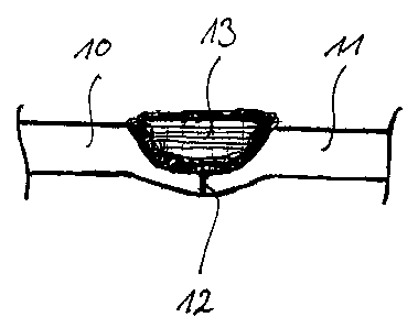
  • At the time of issue of the patent (grant).
(12) Patent Application: (11) CA 2555155
(54) English Title: METHOD FOR CONNECTING COMPONENTS
(54) French Title: PROCEDE DE LIAISON DE PIECES
Status: Deemed Abandoned and Beyond the Period of Reinstatement - Pending Response to Notice of Disregarded Communication
Bibliographic Data
(51) International Patent Classification (IPC):
  • B23K 26/21 (2014.01)
  • F01D 05/30 (2006.01)
(72) Inventors :
  • MEIER, REINHOLD (Germany)
(73) Owners :
  • MTU AERO ENGINES GMBH
(71) Applicants :
  • MTU AERO ENGINES GMBH (Germany)
(74) Agent: MARKS & CLERK
(74) Associate agent:
(45) Issued:
(86) PCT Filing Date: 2005-01-28
(87) Open to Public Inspection: 2005-08-18
Examination requested: 2009-12-09
Availability of licence: N/A
Dedicated to the Public: N/A
(25) Language of filing: English

Patent Cooperation Treaty (PCT): Yes
(86) PCT Filing Number: PCT/DE2005/000132
(87) International Publication Number: DE2005000132
(85) National Entry: 2006-07-31

(30) Application Priority Data:
Application No. Country/Territory Date
10 2004 006 154.8 (Germany) 2004-02-07

Abstracts

English Abstract


The invention relates to a method for connecting dynamically loaded
components, especially gas turbine components. According to the invention, at
least two components (10, 11; 14, 15) to be interconnected are connected by
means of laser powder build-up welding.


French Abstract

Procédé de liaison de pièces sollicitées de manière dynamique, en particulier de pièces de turbines à gaz. Selon la présente invention, au moins deux parties (10, 11; 14, 15) à relier ensemble sont reliées par soudage laser avec apport en poudre.

Claims

Note: Claims are shown in the official language in which they were submitted.

Claims
1. A method for joining components under dynamic load, in particular gas
turbine
components, at least two components to be joined together (10, 11; 14, 15)
being joined together
by laser powder build-up welding,
characterized in that the components to be joined together (10, 11; 14, 15)
are aligned relative to
one another and are joined together in this aligned position by an auxiliary
weld (12; 16).
2. The method as recited in Claim 1,
characterized in that the auxiliary weld (12; 16) is produced by laser welding
or electron-beam
welding.
3. The method as recited in Claim 1 or 2,
characterized in that subsequently to producing the auxiliary weld, the actual
joint of the
components (10, 11; 14, 15) is produced by laser powder build-up welding (13,
17).
4. The method as recited in one or more of Claims 1 through 3,
characterized in that at least two rotor discs of a compressor rotor or a
turbine rotor are joined
together at flanges extending in the axial direction.

Description

Note: Descriptions are shown in the official language in which they were submitted.


CA 02555155 2006-07-31
METHOD FOR CONNECTING COMPONENTS
[0001] The present invention relates to a method for joining components under
dynamic load,
in particular gas turbine components, according to the definition of the
species in Patent Claim I .
[0002) Components of gas turbines under high dynamic loads in particular are
as a rule
manufactured as forgings since forgings have greater strength compared to
castings. According
to the related art, friction welding, in particular rotational friction
welding or linear friction
welding, is used for joining such components under dynamic load. Strength
values, which
correspond to the strength values of the forged material, may be achieved for
the joint area
between two components by using friction welding. Rotational friction welding
is among the
group of what is known as pressure welding techniques which all have the
disadvantage that they
must be carried out on complex machines and involve expensive manufacturing
resources.
Joining components under dynamic load via friction welding or pressure welding
is thus
complex and expensive. Moreover, a welding bulge (known as flash) forms during
friction
welding or pressure welding which requires complex further machining. Fusion
welding
techniques known from the related art, however, cannot be used for joining
components under
dynamic load since the strength of fusion welded joints is not adequate for
components under
high dynamic loads.
[0003) Therefore, the object of the present invention is based on providing a
novel method for
joining components under dynamic load, in particular gas turbine components.
[0004) This object is achieved by a method for joining components under
dynamic load, in
particular gas turbine components, according to Patent Claim 1. According to
the present
invention, at least two components to be joined are joined together using
laser build-up welding.

CA 02555155 2006-07-31
[0005) Within the scope of the present invention it is proposed that
components under dynamic
load be joined using laser powder build-up welding. According to the related
art, laser powder
build-up welding is merely used for manufacturing components or new parts by
way of what is
known as rapid manufacturing processes. The present invention proposes for the
first time the
use of laser powder build-up welding for joining components under dynamic
load. The present
invention is based on the recognition that, using laser powder build-up
welding, joints may be
achieved whose strength values are higher than the strength values of forged
components. This is
due to the fact that in laser powder build-up welding the welded material
cools down rapidly and
freezes in position. The structure of the weld being formed in the process is
fine-grained. The
joint produced in this way thus has outstanding strength characteristics and
is particularly well
suited for joining components under dynamic load. Additional advantages of the
present
invention are the high flexibility of laser powder build-up welding as well as
little pretreatment
and after-treatment complexity of the weld.
(0006) According to an advantageous refinement of the present invention, the
components to
be joined are aligned relative to one another and are joined together in this
aligned position by an
auxiliary weld. Subsequently to producing the auxiliary weld, the actual joint
of the components
is established via laser powder build-up welding.
(0007] Preferred refinements of the present invention arise from the subclaims
and the
following description. Without being restricted thereto, an exemplary
embodiment of the present
invention is explained in greater detail based on the drawing.
[0008) Figure I shows a highly schematized view of two components under
dynamic load
joined by the method according to the present invention, and
(0009) Figure 2 shows a highly schematized view of two additional components
under dynamic
load joined by the method according to the present invention.
2

CA 02555155 2006-07-31
[0010] The present invention is described in greater detail in the following
with reference to
Figures 1 and 2.
(0011] Figure I shows sections of two components to be joined, both components
being
designed as rotor discs of a gas turbine rotor which are to be joined together
on axially extending
flanges 10, I I.
[0012] Within the scope of the method according to the present invention, the
two components
are joined together at flanges 10, 1 I by initially aligning components 10, I
1 relative to one
another and temporarily joining them in this aligned position by an auxiliary
weld 12.
Subsequently to producing auxiliary weld 12, both components are joined
together permanently
by laser powder build-up welding, a weld produced by laser powder build-up
welding being
identified by reference numeral 13 in Figure 1.
[0013] As is apparent in Figure I, flanges 10, 1 I form a pool crater in the
area of the flange
ends to be joined together into which, for establishing weld 13, material for
weld 13 may be
introduced by laser powder build-up welding. The powder used in laser powder
build-up welding
is adapted to the material composition of the components to be joined
together.
[0014] During laser powder build-up welding, the powder is melted and is
subject to a rapid
cool-down so that the melted material freezes in position during coot-down. A
fine-grained
structure forms in the area of weld 13. Weld 13 thus has strength values which
are higher than
the strength values of the base material of the components to be joined
together. Cooling-down
of the material during laser powder build-up welding and thus the strength
value of the resulting
weld 13 may be influenced by appropriate cooling.
(0015] As is apparent in Figure 1, weld 13 produced by laser powder build-up
welding
protrudes slightly over the dimensions of flange 1 O.This section of weld I 3
protruding over
flange 10 may be removed during an after-treatment of weld I 3. However, the
after-treatment
effort is little since it is possible to apply material for forming weld 13 in
a targeted and highly
3

CA 02555155 2006-07-31
accurate manner by laser powder build-up welding.
[0016] Figure 2 shows two additional components to be joined together, namely
two rotor
discs which are to be joined together in the area of axially extending flanges
14 and I5. For
producing the joint of the components at flanges 14, I 5 according to Figure
2, one proceeds in a
way similar to the exemplary embodiment of Figure I in such a way that both
components are
initially aligned relative to one another and joined in this aligned position
with the aid of an
auxiliary weld 16. Subsequently to producing auxiliary weld 16, the actual
joint of the
components is established via a weld 17 which is produced by laser powder
build-up welding.
(0017] The exemplary embodiment of Figure 2 differs from the exemplary
embodiment of
Figure 1 merely by the fact that alignment of the components is facilitated in
that a shoulder-
shaped or step-shaped centering lip 18 exists in the area of the ends of
flanges 14 and 15 to be
joined together. Centering Iip 18 is used for easier alignment of the
components relative to one
another.
[0018] It should be pointed out that a weld 13 having a gradient may also be
produced in that
the material used for laser powder build-up welding is adapted, for example,
or that the welding
conditions, such as the temperature, are modified.
(00I9] Using the present invention, joints on components under high dynamic
loads may be
produced cost-effectively without applying the great force required in
friction welding. This
makes it possible to dispense with complex equipment, machines, and special
manufacturing
resources. Laser powder build-up welding is very flexible and requires only
tittle after-treatment
of the weld. Strength values of the weld may be achieved which are higher than
the strength
values of the base material of the components to be joined together.
4

Representative Drawing
A single figure which represents the drawing illustrating the invention.
Administrative Status

2024-08-01:As part of the Next Generation Patents (NGP) transition, the Canadian Patents Database (CPD) now contains a more detailed Event History, which replicates the Event Log of our new back-office solution.

Please note that "Inactive:" events refers to events no longer in use in our new back-office solution.

For a clearer understanding of the status of the application/patent presented on this page, the site Disclaimer , as well as the definitions for Patent , Event History , Maintenance Fee  and Payment History  should be consulted.

Event History

Description Date
Inactive: IPC deactivated 2016-01-16
Inactive: First IPC assigned 2015-08-28
Inactive: IPC assigned 2015-08-28
Inactive: IPC expired 2014-01-01
Application Not Reinstated by Deadline 2013-06-25
Inactive: Dead - No reply to s.30(2) Rules requisition 2013-06-25
Deemed Abandoned - Failure to Respond to Maintenance Fee Notice 2013-01-28
Inactive: Abandoned - No reply to s.30(2) Rules requisition 2012-06-22
Inactive: S.30(2) Rules - Examiner requisition 2011-12-22
Amendment Received - Voluntary Amendment 2011-03-25
Amendment Received - Voluntary Amendment 2010-07-06
Letter Sent 2010-01-22
Request for Examination Requirements Determined Compliant 2009-12-09
Request for Examination Received 2009-12-09
All Requirements for Examination Determined Compliant 2009-12-09
Inactive: IPRP received 2008-02-06
Letter Sent 2006-11-23
Inactive: Single transfer 2006-10-16
Inactive: Courtesy letter - Evidence 2006-10-03
Inactive: Cover page published 2006-10-02
Inactive: Notice - National entry - No RFE 2006-09-27
Application Received - PCT 2006-09-07
Inactive: IPRP received 2006-08-01
National Entry Requirements Determined Compliant 2006-07-31
Application Published (Open to Public Inspection) 2005-08-18

Abandonment History

Abandonment Date Reason Reinstatement Date
2013-01-28

Maintenance Fee

The last payment was received on 2011-12-29

Note : If the full payment has not been received on or before the date indicated, a further fee may be required which may be one of the following

  • the reinstatement fee;
  • the late payment fee; or
  • additional fee to reverse deemed expiry.

Patent fees are adjusted on the 1st of January every year. The amounts above are the current amounts if received by December 31 of the current year.
Please refer to the CIPO Patent Fees web page to see all current fee amounts.

Fee History

Fee Type Anniversary Year Due Date Paid Date
Basic national fee - standard 2006-07-31
MF (application, 2nd anniv.) - standard 02 2007-01-29 2006-07-31
Registration of a document 2006-10-16
MF (application, 3rd anniv.) - standard 03 2008-01-28 2007-12-21
MF (application, 4th anniv.) - standard 04 2009-01-28 2009-01-07
Request for examination - standard 2009-12-09
MF (application, 5th anniv.) - standard 05 2010-01-28 2009-12-23
MF (application, 6th anniv.) - standard 06 2011-01-28 2010-12-29
MF (application, 7th anniv.) - standard 07 2012-01-30 2011-12-29
Owners on Record

Note: Records showing the ownership history in alphabetical order.

Current Owners on Record
MTU AERO ENGINES GMBH
Past Owners on Record
REINHOLD MEIER
Past Owners that do not appear in the "Owners on Record" listing will appear in other documentation within the application.
Documents

To view selected files, please enter reCAPTCHA code :


To view images, click a link in the Document Description column. To download the documents, select one or more checkboxes in the first column and then click the "Download Selected in PDF format (Zip Archive)" or the "Download Selected as Single PDF" button.

List of published and non-published patent-specific documents on the CPD .

If you have any difficulty accessing content, you can call the Client Service Centre at 1-866-997-1936 or send them an e-mail at CIPO Client Service Centre.


Document
Description 
Date
(yyyy-mm-dd) 
Number of pages   Size of Image (KB) 
Claims 2010-07-05 1 43
Description 2006-07-30 4 177
Abstract 2006-07-30 1 63
Drawings 2006-07-30 1 11
Claims 2006-07-30 1 23
Representative drawing 2006-09-28 1 5
Description 2010-07-05 5 211
Notice of National Entry 2006-09-26 1 192
Courtesy - Certificate of registration (related document(s)) 2006-11-22 1 105
Reminder - Request for Examination 2009-09-28 1 116
Acknowledgement of Request for Examination 2010-01-21 1 176
Courtesy - Abandonment Letter (R30(2)) 2012-09-16 1 164
Courtesy - Abandonment Letter (Maintenance Fee) 2013-03-24 1 173
PCT 2006-07-30 5 123
PCT 2006-07-31 5 205
Correspondence 2006-09-26 1 26
PCT 2006-08-01 5 188