Note: Descriptions are shown in the official language in which they were submitted.
CA 02555182 2006-08-01
WO 2005/093717 PCT/IB2004/000715
SYNTHESIZING A MONO AUDIO SIGNAL BASED ON AN ENCODED MULTICHANNEL AUDIO SIGNAL
FIELD OF THE INVENTION
The invention relates to a method of synthesizing a mono
audio signal based on an available encoded multichannel
audio signal, which encoded multichannel audio signal
comprises at least for a part of an audio frequency band
separate parameter values for each channel of the
multichannel audio signal. The invention relates equally
to a corresponding audio decoder, to a corresponding
coding system and to a corresponding software program
product.
BACKGROUND OF THE INVENTION
Audio coding systems are well known from the state of the
art. They are used in particular for transmitting or
storing audio signals.
An audio coding system which is employed for transmission
of audio signals comprises an encoder at a transmitting
end and a decoder at a receiving end. The transmitting
end and the receiving end can be for instance mobile
terminals. An audio signal that is to be transmitted is
provided to the encoder. The encoder is responsible for
adapting the incoming audio data rate to a bitrate level
at which the bandwidth conditions in the transmission
channel are not violated. Ideally, the encoder discards
only irrelevant information from the audio signal in this
encoding process. The encoded audio signal is then
transmitted by the transmitting end of the audio coding
CA 02555182 2006-08-01
WO 2005/093717 PCT/IB2004/000715
2 -
system and received at the receiving end of the audio
coding system. The decoder at the receiving end reverses
the encoding process to obtain a decoded audio signal
with little or no audible degradation.
If the audio coding system is employed for archiving
audio data, the encoded audio data provided by the
encoder is stored in some storage unit, and the decoder
decodes audio data retrieved from this storage unit, for
instance for presentation by some media player. In this
alternative, it is the target that the encoder achieves a
bitrate which is as low as possible, in order to save
storage space.
Depending on the allowed bitrate, different encoding
schemes can be applied to an audio signal.
In most cases, a lower frequency band and a higher
frequency band of an audio signal correlate with each
other. Audio codec bandwidth extension algorithms
therefore typically first split the bandwidth of the to
be encoded audio signal into two frequency bands. The
lower frequency band is then processed independently by a
so called core codec, while the higher frequency band is
processed using knowledge about the coding parameters and
signals from the lower frequency band. Using parameters
from the low frequency band coding in the high frequency
band coding reduces the bit rate resulting in the high
band encoding significantly.
Figure 1 presents a typical split band encoding and
decoding system. The system comprises an audio encoder 10
and an audio decoder 20. The audio encoder 10 includes a
two band analysis filterbank 11, a low band encoder 12
CA 02555182 2006-08-01
WO 2005/093717 PCT/IB2004/000715
3 -
and a high band encoder 13. The audio decoder 20 includes
a low band decoder 21, a high band decoder 22 and a two
band synthesis filterbank 23. The low band encoder 12 and
decoder 21 can be for example the Adaptive Multi-Rate
Wideband (AMR-WB) standard encoder and decoder, while the
high band encoder 13 and decoder 22 may comprise either
an independent coding algorithm, a bandwidth extension
algorithm or a combination of both. By way of example,
the presented system is assumed to use the extended AMR-
WB (AMR-WB+) codec as split band coding algorithm.
An input audio signal 1 is first processed by the two-
band analysis filterbank 11, in which the audio frequency
band is split into a lower frequency band and a higher
frequency band. For illustration, figure 2 presents an
example of a frequency response of a two-band filterbank
for the case of AMR-WB+. A 12 kHz audio band is divided
into a 0 kHz to 6.4 kHz band L and a 6.4 kHz to 12 kHz
band H. in the two-band analysis filterbank 11, the
resulting frequency bands are moreover critically down-
sampled. That is, the low frequency band is down-sampled
to 12.8 kHz and the high frequency band is re-sampled to
11.2 kHz_
The low frequency band and the high frequency band are
then encoded independently of each other by the low band
encoder 12 and the high band encoder 13, respectively.
The low band encoder 12 comprises to this end full source
signal encoding algorithms. The algorithms include an
algebraic code excitation linear prediction (ACELP) type
of algorithm and a transform based algorithm. The
actually employed algorithm is selected based on the
signal characteristics of the respectively input audio
CA 02555182 2006-08-01
WO 2005/093717 PCT/IB2004/000715
4 -
signal. The ACELP algorithm is typically selected for
encoding speech signals and transients, while the
transform based algorithm is typically selected for
encoding music and tone like signals to better handle the
frequency resolution.
In an AMR-WB+ codec, the high band encoder 13 utilizes a
linear prediction coding (LPC) to model the spectral
envelope of the high frequency band signal. The high
frequency band can then be described by means of LPC
synthesis filter coefficients which define the spectral
characteristics of the synthesized signal, and gain
factors for an excitation signal which control the
amplitude of the synthesized high frequency band audio
signal. The high band excitation signal is copied from
the low band encoder 12. Only the LPC coefficients and
the gain factors are provided for transmission.
The output of the low band encoder 12 and of the high
band encoder 13 are multiplexed to a single bit stream 2.
The multiplexed bit stream 2 is transmitted for example
through a communication channel to the audio decoder 20,
in which the low frequency band and the high frequency
band are decoded separately.
In the low band decoder 21, the processing in the low
band encoder 12 is reversed for synthesizing the low
frequency band audio signal.
In the high band decoder 22, an excitation signal is
generated by re-sampling a low frequency band excitation
provided by the low band decoder 21 to the sampling rate
used in the high frequency band. That is, the low
CA 02555182 2006-08-01
WO 2005/093717 PCT/IB2004/000715
-
frequency band excitation signal is reused for decoding
of the high frequency band by transposing the low
frequency band signal to the high frequency band.
Alternatively, a random excitation signal could be
5 generated for the reconstruction of the high frequency
band signal. The high frequency band signal is then
reconstructed by filtering the scaled excitation signal
through the high band LPC model defined by the LPC
coefficients.
In the two band synthesis filterbank 23, the decoded low
frequency band signals and the high frequency band
signals are up-sampled to the original sampling frequency
and combined to a synthesized output audio signal 3.
The input audio signal 1 which is to be encoded can be a
mono audio signal or a multichannel audio signal
containing at least a first and a second channel signal.
An example of a multichannel audio signal is a stereo
audio signal, which is composed of a left channel signal
and a right channel signal.
For a stereo operation of an AMR-WB+ codec, the input
audio signal is equally split into a low frequency band
signal and a high frequency band signal in the two band
analysis filterbank 11. The low band encoder 12 generates
a mono signal by combining the left channel signals and
the right channel signals in the low frequency band. The
mono signal is encoded as described above. In addition,
the low band encoder 12 uses a parametric coding for
encoding the differences of the left and right channel
signals to the mono signal. The high band encoder 13
encodes the left channel and the right channel separately
CA 02555182 2006-08-01
WO 2005/093717 PCT/IB2004/000715
6 -
by determining separate LPC coefficients and gain factors
for each channel.
In case the input audio signal 1 is a multichannel audio
signal, but the device which is to present the
synthesized audio signal 3 does not support a
multichannel audio output, the incoming multichannel bit
stream 2 has to be converted by the audio decoder 20 into
a mono audio signal. At the low frequency band, the
conversion of the multichannel signal to a mono signal is
straightforward, since the low band decoder 21 can simply
omit the stereo parameters in the received bit stream and
decode only the mono part. But for the high frequency
band, more processing is required, as no separate mono
signal part of the high frequency band is available in
the bit stream.
Conventionally, the stereo bit stream for the high
frequency band is decoded separately for left and right
channel signals, and the mono signal is then created by
combining the left and right channel signals a in down-
mixing process. This approach is illustrated in Figure 3.
Figure 3 schematically presents details of the high band
decoder 22 of Figure 1 for a mono audio signal output.
The high band decoder comprises to this end a left
channel processing portion 30 and a right channel
processing portion 33. The left channel processing
portion 30 includes a mixer 31, which is connected to an
LPC synthesis filter 32. The right channel processing
portion 33 includes equally a mixer 34, which is
connected to an LPC synthesis filter 35. The output of
both LPC synthesis filters 32, 35 is connected to a
further mixer 36.
CA 02555182 2006-08-01
WO 2005/093717 PCT/IB2004/000715
7 -
A low frequency band excitation signal which is provided
by the low band decoder 21 is fed to either of the mixers
31 and 34. The mixer 31 applies the gain factors for the
left channel to the low frequency band excitation signal.
The left channel high band signal is then reconstructed
by the LPC synthesis filter 32 by filtering the scaled
excitation signal through a high band LPC model defined
by the LPC coefficients. for the left channel. The mixer
34 applies the gain factors for the right channel to the
low frequency band excitation signal. The right channel
high band signal is then reconstructed by the LPC
synthesis filter 35 by filtering the scaled excitation
signal through a high band LPC model defined by the LPC
coefficients for the right channel.
The reconstructed left channel high frequency band signal
and the reconstructed right channel high frequency band
signal are then converted by the mixer 36 into a mono
high frequency band signal by computing their average in
the time domain.
This is, in principle, a simple and working approach.
However, it requires a separate synthesizing of multiple
channels, even though, in the end, only a single channel
signal is needed.
Furthermore, if the multichannel audio input signal 1 is
unbalanced in such a way that most of the energy of the
multichannel audio signal lies on one of the channels, a
direct mixing of multichannels by computing their average
will result in an attenuation in the combined signal. In
an extreme case, one of the channels is completely
silent, which leads to an energy level of the combined
CA 02555182 2009-10-14
8 -
signal which is half of the energy level of the original active
input channel.
SUMMARY OF THE INVENTION
It is an object of the invention to reduce the processing load
which is required for synthesizing a mono audio signal based on
an encoded multichannel audio signal.
Accordingly, in one aspect of the present invention there is
provided a method of synthesizing a mono audio signal based on
an available encoded multichannel audio signal, which encoded
multichannel audio signal comprises at least for a part of an
audio frequency band separate parameter values for each channel
of said multichannel audio signal, said method comprising at
least for a part of an audio frequency band:
combining parameter values of said multiple channels in the
parameter domain; and
using said combined parameter values for synthesizing a
mono audio signal,
wherein combining said parameter values is controlled for
at least one parameter based on information on the respective
activity in said multiple channels.
According to another aspect of the present invention there is
provided an audio decoder for synthesizing a mono audio signal
based on an available encoded multichannel audio signal, which
encoded multichannel audio signal comprises at least for a part
of the frequency band of an original multichannel audio signal
separate parameter values for each channel of said multichannel
audio signal, said audio decoder comprising:
at least one parameter selection portion adapted to combine
parameter values of said multiple channels in the parameter
domain at least for a part of the frequency band of said
multichannel audio signal; and
an audio signal synthesis portion adapted to synthesize a
mono audio signal at least for a part of the frequency band of
CA 02555182 2009-10-14
9 -
said multichannel audio signal based on combined parameter
values provided by said at least one parameter selection
portion,
wherein said parameter selection portion is adapted to
combine said parameter values for at least one parameter based
on information on the respective activity in said multiple
channels.
Moreover, a coding system is proposed, which comprises in
addition to the proposed decoder an audio encoder providing
the encoded multichannel audio signal.
Finally, a software program product is proposed, in which a
software code for synthesizing a mono audio signal based on an
available encoded multichannel audio signal is stored.
The encoded multichannel audio signal comprises at least for a
part of the frequency band of an original multichannel audio
signal separate parameter values for each channel of the
multichannel audio signal. The proposed software code
realizes the steps of the proposed method when running in an
audio decoder.
The encoded multichannel audio signal can be in particular,
though not exclusively, an encoded stereo audio signal.
The invention proceeds from the consideration that for
obtaining a mono audio signal, a separate decoding of
available multiple channels can be avoided, if parameter
values which are available for these multiple channels are
combined already in the parameter domain before the decoding.
The combined parameter values can then be used for a single
channel decoding.
It is an advantage of the invention that it allows saving
processing load at a decoder and that it reduces the
complexity of the decoder. If the multiple channels are
stereo channels which are processed in a split band
CA 02555182 2006-08-01
WO 2005/093717 PCT/IB2004/000715
- 10 -
system, for example, approximately half of the processing
load required for a high frequency band synthesis
filtering can be saved compared to performing the high
frequency band synthesis filtering separately for both
channels and mixing the resulting left and right channel
signals.
In one embodiment of the invention, the parameters
comprise gain factors for each of the multiple channels
and linear prediction coefficients for each of the
multiple channels.
Combining the parameter values may be realized in static
manner, for instance by generally computing the average
of the available parameter values over all channels.
Advantageously, however, combining the parameter values
is controlled for at least one parameter based on
information on the respective activity in the multiple
channels. This allows to achieve a mono audio signal with
spectral characteristics and with a signal l.evel as close
as possible to the spectral characteristics and to the
signal level in a respective active channel, and thus an
improved audio quality of the synthesized mono audio
signal.
If the activity in a first channel is significantly
higher than in a second channel, the first channel can be
assumed to be an active channel, while the second channel
can be assumed to be a silent channel which provides
basically no audible contribution to the original audio
signal. In case a silent channel is present, the
parameter values of at least one parameter are
advantageously disregarded completely when combining the
parameter values. As a result, the synthesized mono
CA 02555182 2006-08-01
WO 2005/093717 PCT/IB2004/000715
- 11 -
signal will be similar to the active channel. In all
other cases, the parameter values may be combined for
example by forming the average or a weighted average over
all channels. For a weighted average, the weight assigned
to a channel rises with its relative activity compared to
the other channel or channels. Other methods can be used
as well for realizing the combining. Equally, parameter
values for a silent channel which are not to be discarded
may be combined with the parameter values of an active
channel by averaging or some other method.
Various types of information may form the information on
the respective activity in the multiple channels. It may
be given for example by a gain factor for each of the
multiple channels, by a combination of gain factors over
a short period of time for each of the multiple channels,
or by linear prediction coefficients for each of the
multiple channels. The activity information may equally
be given by the energy level in at least part of the
frequency band of the multichannel audio signal for each
of the multiple channels, or by separate side information
on the activity received from an encoder providing the
encoded multichannel audio signal.
For obtaining the encoded multichannel audio signal, an
original multichannel audio signal may be split for
example into a low frequency band signal and a high
frequency band signal. The low frequency band signal may
then be encoded in a conventional manner. Also the high
frequency band signal may be encoded separately for the
multiple channels in a conventional manner, which results
in parameter values for each of the multiple channels. At
least the encoded high frequency band part of the entire
CA 02555182 2006-08-01
WO 2005/093717 PCT/IB2004/000715
- 12 -
encoded multichannel audio signal may then be treated in
accordance with the invention.
It has to be understood, though, that equally
multichannel parameter values of a low frequency band
part of the entire signal can be treated in accordance
with the invention, in order to prevent an imbalance
between the low frequency band and the high frequency
band, for example an imbalance in the signal level.
Alternatively, the parameter values for silent channels
in the high frequency band which influence the signal
level might not be discarded in principle, but only the
parameter values for silent channels which influence the
spectral characteristic of the signal.
The invention may be implemented for example, though not
exclusively, in an AMR-WB+ based coding system.
Other objects and features of the present invention will
become apparent from the following detailed description
considered in conjunction with the accompanying drawings.
BRIEF DESCRIPTION OF THE FIGURES
Fig. 1 is a schematic block diagram of a split band
coding system;
Fig. 2 is a diagram of the frequency response of a two-
band filterbank;
Fig. 3 is a schematic block diagram of a conventional
high band decoder for stereo to mono conversion;
Fig. 4 is a schematic block diagram of high band decoder
for stereo to mono conversion according to a
first embodiment of the invention;
CA 02555182 2006-08-01
WO 2005/093717 PCT/IB2004/000715
- 13 -
Fig. 5 is a diagram illustrating the frequency response
for stereo signals and for the mono signal
resulting with the high band decoder of Figure 4;
Fig. 6 is a schematic block diagram of high band decoder
for stereo to mono conversion according to a
second embodiment of the invention;
Fig. 7 is a flow chart illustrating the operation in a
system using the high band decoder of Figure 6;
Fig. 8 is a flow chart illustrating a first option for
the parameter combining in the flow chart of
Figure 7; and
Fig. 9 is a flow chart illustrating a second option for
the parameter combining in the flow chart of
Figure 7.
DETAILED DESCRIPTION OF THE INVENTION
The invention is assumed to be implemented in the system
of Figure 1, which will therefore be referred to as well
in the following. A stereo input audio signal 1 is
provided to the audio encoder 10 for encoding, while a
decoded mono audio signal 3 has to be provided by the
audio decoder 20 for presentation.
In order to be able to provide such a mono audio signal 3
with a low processing load, the high band decoder 22 of
the system may be realized in accordance with a first,
simple embodiment of the invention.
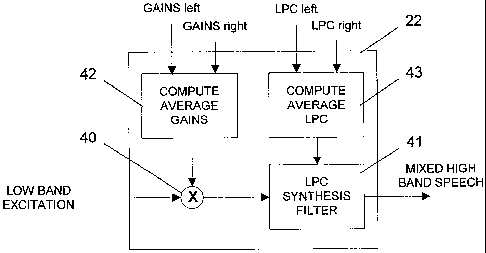
Figure 4 is a schematic block diagram of this high band
decoder 22. A low band excitation input of the high band
decoder 22 is connected via a mixer 40 and an LPC
synthesis filter 41 to the output of the high band
decoder 22. The high band decoder 22 comprises in
CA 02555182 2006-08-01
WO 2005/093717 PCT/IB2004/000715
- 14 -
addition a gain average computation block 42 which is
connected to the mixer and an LPC average computation
block 43 which is connected to the LPC synthesis filter
41.
The system operates as follows.
A stereo signal input to the audio encoder 10 is split by
the two band analysis filterbank 11 into a low frequency
band and a high frequency band. A low band encoder 11
encodes the low frequency band audio signal as described
above. An AMR-WB+ high band encoder 12 encodes the high
band stereo signal separately for left and right
channels. More specifically, it determines gain factors
and linear prediction coefficients for each channel as
described above.
The encoded mono low frequency band signal, the stereo
low frequency band parameter values and the stereo high
frequency band parameter values are transmitted in a bit
stream 2 to the audio decoder 20.
The low band decoder 21 receives the low frequency band
part of the bit stream for decoding. In this decoding, it
omits the stereo parameters and decodes only the mono
part. The result is a mono low frequency band audio
signal.
The high band decoder 22 receives on the one hand the
high frequency band parameter values from the transmitted
bit stream and on the other hand the low band excitation
signal output by the low band decoder 21.
CA 02555182 2006-08-01
WO 2005/093717 PCT/IB2004/000715
- 15 -
The high frequency band parameters comprise respectively
a left channel gain factor, a right channel gain factor,
left channel LPC coefficients and right channel LPC
coefficients. In the gain average computation block 42,
the respective gain factors for the left channel and the
right channel are averaged, and the average gain factor
is used by the mixer 40 for scaling the low band
excitation signal. The resulting signal is provided for
filtering to the LPC synthesis filter 41.
In the average LPC computation block 43, the respective
linear prediction coefficients for the left channel and
the right channel are combined. InAMR-WB+, the
combination of the LPC coefficients from both channels
can be made for instance by computing the average over
the received coefficients in the Immittance Spectral Pair
(ISP) domain. The average coefficients are then used for
configuring the LPC synthesis filter 41, to which the
scaled low band excitation signal is subjected.
The scaled and filtered low band excitation signal forms
the desired mono high.band audio signal.
The mono low band audio signal and the mono high band
audio signal are combined in the two band synthesis
filterbank 23, and the resulting synthesized signal 3 is
output for presentation.
Compared to a system using the high band encoder of
Figure 3, a system using the high band encoder of Figure
4 has the advantage that it requires only approximately
half of the processing power for generating the
synthesized signal since it is only generated once.
CA 02555182 2006-08-01
WO 2005/093717 PCT/IB2004/000715
- 16 -
It has to be noted that the above mentioned problem of a
possible attenuation in the combined signal in case of a
stereo audio input having an active signal in only one of
the channels remains, though.
Furthermore, for stereo audio input signals with only one
active channel the averaging of linear prediction
coefficients brings an undesired side effect of
'flattening' the spectrum in the resulting combined
signal. Instead of having the spectral characteristics of
the active channel, the combined signal has somewhat
distorted spectral characteristics due to the combination
of the 'real' spectrum of the active channel and a
practically flat or random-like spectrum of the silent
channel.
This effect is illustrated in Figure 5. Figure 5 is a
diagram which depicts the amplitude over the frequency
for three different LPC synthesis filter frequency
responses computed over a frame of 80 ms. A solid line
represents the LPC synthesis filter frequency response of
an active channel. A dotted line represents the LPC
synthesis filter frequency response of a silent channel.
A dashed line represents the LPC synthesis filter
frequency response resulting when averaging the LPC
modules from both channels in the ISP domain. It can be
seen that the averaged LPC filter creates a spectrum
which does not closely resemble either of the real
spectra. In practice this phenomenon can be heard as
reduced audio quality at the high frequency band.
In order to be able to provide a mono audio signal 3 not
only with a low processing load but further avoiding the
constraints which are not solved with the high band
CA 02555182 2006-08-01
WO 2005/093717 PCT/IB2004/000715
- 17 -
decoder of Figure 4, the high band decoder 22 of the
system of Figure 1 may be realized in accordance with a
second embodiment of the invention.
Figure 6 is a schematic block diagram of such a high band
decoder 22. A low band excitation input of the high band
decoder 22 is connected via a mixer 60 and an LPC
synthesis filter 61 to the output of the high band
decoder 22. The high band decoder 22 comprises in
addition a gain selection logic 62 which is connected to
the mixer 60, and an LPC selection logic 63 which is
connected to the LPC synthesis filter 61.
The processing in a system using the high band encoder 22
of Figure 6 will now be described with reference to
Figure 7. Figure 7 is a flow chart which depicts in its
upper part the processing in the audio encoder 10 and in
its lower part the processing in the audio decoder 20 of
the system. The upper part and the lower part are divided
by a horizontal dashed line.
A stereo audio signal input 1 to the encoder is split
into a low frequency band and a high frequency band by
the two band analysis filterbank 11. A low band encoder
12 encodes the low frequency band. An AMR-WB+ high band
encoder 13 encodes the high frequency band separately for
left and right channels. More specifically, it determines
dedicated gain factors and linear prediction coefficients
for both channels as high frequency band parameters.
The encoded mono low frequency band signal, the stereo
low frequency band parameter values and the stereo high
frequency band parameter values are transmitted in a bit
stream 2 to the audio decoder 20.
CA 02555182 2006-08-01
WO 2005/093717 PCT/IB2004/000715
- 18 -
The low band decoder 21 receives the low frequency band
related part of the bit stream 2, and decodes this part.
In the decoding, the low band decoder 21 omits the
received stereo parameters and decodes only the mono
part. The result is a mono low band audio signal.
The high band decoder 22 receives on the one hand a left
channel gain factor, a right channel gain factor, linear
prediction coefficients for the left channel and linear
prediction coefficients for the right channel, and on the
other hand the low band excitation signal output by the
low band decoder 21. The left channel gain and the right
channel gain are used at the same time as channel
activity information. It has to be noted that instead,
some other channel activity information indicating the
activity distribution in the high frequency band to the
left channel and the right channel could be provided as
additional parameter by the high band encoder 13.
The channel activity information is evaluated, and the
gain factors for the left channel and the right channel
are combined by the gain selection logic 62 according to
the evaluation to a single gain factor. The selected gain
is then applied to the low frequency band excitation
signal provided by the low band decoder 21 by means of
the mixer 60.
Moreover, the LPC coefficients for the left channel and
the right channel are combined by the LPC model selection
logic 63 according to the evaluation to a single
set of LPC coefficients. The combined LPC model is
supplied to the LPC synthesis filter 61. The LPC
synthesis filter 61 applies the selected LPC model to the
CA 02555182 2006-08-01
WO 2005/093717 PCT/IB2004/000715
- 19 -
scaled low frequency band excitation signal provided by
the mixer 60.
The resulting high frequency band audio signal is then
combined in the two band synthesis filterbank 23 with the
mono low frequency band audio signal to a mono full band
audio signal, which may be output for presentation by a
device or an application which is not capable of
processing stereo audio signals.
The proposed evaluation of the channel activity
information and the subsequent combination of the
parameter values, which are indicated in the flow chart
of Figure 7 as a block with double lines, can be
implemented in different ways. Two options will be
presented with reference to the flow charts of Figures 8
and 9.
In the first option illustrated in Figure 8, the gain
factors for the left channel are first averaged over the
duration of one frame, and equally, the gain factors for
the right channel are averaged over the duration of one
frame.
The averaged right channel gain is then subtracted from
the averaged left channel gain, resulting in a certain
gain difference for each frame.
In case the gain difference is smaller than a first
threshold value, the combined gain factors for this frame
are set equal to the gain factors provided for the right
channel. Moreover, the combined LPC models for this frame
are set to be equal to the LPC models provided for the
right channel.
CA 02555182 2006-08-01
WO 2005/093717 PCT/IB2004/000715
- 20 -
In case the gain difference is larger than a second
threshold value, the combined gain factors for this frame
are set equal to the gain factors provided for the left
channel. Moreover, the combined LPC models for this frame
are set to be equal to the LPC models provided for the
left channel.
In all other cases, the combined gain factors for this
frame are set equal to the average over the respective
gain factor for the left channel and the respective gain
factor for the right channel. The combined LPC models for
this frame are set to be equal to the average over the
respective LPC model for the left channel and the
respective LPC model for the right channel.
The first threshold value and the second threshold value
are selected depending on the required sensitivity and
the type of the application for which the stereo to mono
conversion is required. Suitable values are for example
-20 dB for the first threshold value and 20 dB for the
second threshold value.
Thus, if one of the channels can be considered as a
silent channel while the other channel can be considered
as an active channel during a respective frame, due to
the large differences in the average gain factors, the
gain factors and LPC models of the silent channel are
disregarded for the duration of the frame. This is
possible, as the silent channel has no audible
contribution to the mixed audio output. Such a
combination of parameter values ensures that the spectral
characteristics and the signal level are as close as
possible to the respective active channel.
CA 02555182 2006-08-01
WO 2005/093717 PCT/IB2004/000715
- 21 -
It has to be noted that instead of omitting the stereo
parameters, also the low band decoder could form combined
.parameter values and apply them to the mono part of the
signal, just as described for the high frequency band
processing.
In the second option of combining parameter values
illustrated in Figure 9, the gain factors for the left
channel and the gain factors for the right channel,
respectively, are averaged as well over the duration of
one frame.
The averaged right channel gain is then subtracted from
the averaged left channel gain, resulting in a certain
gain difference for each frame.
In case the gain difference is smaller than a first, low
threshold value, the combined LPC models for this frame
are set to be equal to the provided LPC models for the
right channel.
In case the gain difference is larger than a second, high
threshold value, the combined LPC models for this frame
are set to be equal to the provided LPC models for the
left channel.
In all other cases, the combined LPC models for this
frame are set to be equal to the average over the
respective LPC model for the left channel and the
respective LPC model for the right channel.
The combined gain factors for the frame are set in any
case equal to the average over the respective gain factor
CA 02555182 2006-08-01
WO 2005/093717 PCT/IB2004/000715
- 22 -
for the left channel and the respective gain factor for
the right channel.
The LPC coefficients have a direct effect only on the
spectral characteristics of the synthesized signal.
Combining only the LPC coefficients thus results in the
desired spectral characteristics, but does not solve the
problem of the signal attenuation. This has the
advantage, however, that the balance between the low
frequency band and the high frequency band is preserved,
in case the low frequency band is not mixed in accordance
with the invention. Preserving the signal level at the
high frequency band would change the balance between the
low frequency bands and the high frequency bands by
introducing relatively too loud signals in the high
frequency band, which leads to a possibly reduced
subjective audio quality.
It has to be noted that the described embodiments are
only some of a wide variety embodiments which can further
be amended in many ways.