Language selection

Search

Patent 2555241 Summary

Third-party information liability

Some of the information on this Web page has been provided by external sources. The Government of Canada is not responsible for the accuracy, reliability or currency of the information supplied by external sources. Users wishing to rely upon this information should consult directly with the source of the information. Content provided by external sources is not subject to official languages, privacy and accessibility requirements.

Claims and Abstract availability

Any discrepancies in the text and image of the Claims and Abstract are due to differing posting times. Text of the Claims and Abstract are posted:

  • At the time the application is open to public inspection;
  • At the time of issue of the patent (grant).
(12) Patent: (11) CA 2555241
(54) English Title: METHOD FOR TRIGGERING AND CONTROLLING THE LATERAL BUCKLING IN UNDERWATER PIPELINES
(54) French Title: PROCEDE PERMETTANT DE DECLENCHER ET DE REGLER LE DEVERSEMENT DANS DES PIPELINES SOUS-MARINS
Status: Expired and beyond the Period of Reversal
Bibliographic Data
(51) International Patent Classification (IPC):
  • F16L 1/024 (2006.01)
  • F16L 1/12 (2006.01)
  • F16L 3/00 (2006.01)
(72) Inventors :
  • MONTI, PAOLO (Italy)
  • CASOLA, FLORIANO (Italy)
  • BRANDUARDI, LUCA (Italy)
(73) Owners :
  • SAIPEM ENERGY INTERNATIONAL S.P.A.
(71) Applicants :
  • SAIPEM ENERGY INTERNATIONAL S.P.A. (Italy)
(74) Agent: ROBIC AGENCE PI S.E.C./ROBIC IP AGENCY LP
(74) Associate agent:
(45) Issued: 2012-07-24
(86) PCT Filing Date: 2005-02-04
(87) Open to Public Inspection: 2005-09-01
Examination requested: 2009-12-23
Availability of licence: N/A
Dedicated to the Public: N/A
(25) Language of filing: English

Patent Cooperation Treaty (PCT): Yes
(86) PCT Filing Number: PCT/EP2005/001222
(87) International Publication Number: WO 2005080845
(85) National Entry: 2006-08-03

(30) Application Priority Data:
Application No. Country/Territory Date
MI2004A000300 (Italy) 2004-02-23

Abstracts

English Abstract


Method for triggering and controlling the lateral buckling in underwater
pipelines by the installation of supporting systems, positioned in certain
points of the seabed, char~acterized in that the upper surfaces of said
supports, on which the pipelines rest, are tilted with respect to the
horizontal plane, transversally with respect to the direc~tion of said
pipelines.


French Abstract

L'invention concerne un procédé qui permet de déclencher et de régler le déversement dans des pipelines sous-marins par l'installation de systèmes de support, positionnés en certains points du fond marin. Ce procédé est caractérisé en ce que les surfaces supérieures de ces supports, sur lesquels reposent les pipelines, sont inclinées par rapport au plan horizontal, transversalement par rapport à la direction desdits pipelines.

Claims

Note: Claims are shown in the official language in which they were submitted.

WHAT IS CLAIMED IS:
1. A method for triggering and controlling the lateral buckling of underwater
pipelines by installation of supporting systems positioned in certain points
of a
seabed, characterized in that said supporting systems have upper surfaces on
which
the pipelines rest, said upper surfaces being tilted with respect to an
horizontal plane,
transversally with respect to the direction of said pipelines, such creating a
lateral
force acting on the pipeline, in relation to the weight of the line and
inclination angle
of the surface, which predetermines the direction of the downward transversal
movement of the pipelines on the upper surfaces of the supporting systems.
2. The method according to claim 1, comprising the following steps:
.cndot. installation of the supporting systems in certain points of the
seabed; and
.cndot. laying of the underwater pipelines by resting them on the upper
surfaces of said
supporting systems.
3. The method according to claim 2, wherein the underwater pipelines are
rested
on the upper surfaces of the supporting systems and also have funnels formed
by
structures present around a higher end of a carrying structure of said
supporting
systems.
4. The method according to claim 3, wherein at least part of the structures
present at the higher end of the carrying structure are removed after the
pipelines
have been rested on the upper surfaces.
5. The method according to any one of claims 1 to 4, wherein the inclination
angle of the upper surface with respect to the horizontal plane ranges from 3
to 30°.
6. The method according to claim 5, wherein said inclination angle ranges from
5
to 15°.

11
7. The method according to any one of the claims 1 to 6, wherein the upper
surface of each of said supporting systems has a constant inclination.
8. The method according to any one of claims 1 to 6, wherein the upper surface
of each of said supporting systems has a varying inclination in one or more
points.
9. The method according to any one of claims 1 to 6, wherein the upper surface
of each of said supporting systems consists of a succession of sections with a
varying inclination alternating with horizontal stretches.
10. The method according to any one of claims 1 to 9, wherein the upper
surface
of each of said supporting systems has a final section that is counter-
inclined.
11. The method according to any one of claims 1 to 10, wherein said upper
surfaces are coated with material having a defined friction coefficient.
12. The method according to any one of claims 1 to 10, wherein said upper
surfaces and the pipelines have a friction defined by means of supporting
rollers.

Description

Note: Descriptions are shown in the official language in which they were submitted.


CA 02555241 2006-08-03
WO 2005/080845 PCT/EP2005/001222
METHOD FOR TRIGGERING AND CONTROLLING THE LATERAL BUCKLING
IN UNDERWATER PIPELINES
The present invention relates to a method for triggering
and controlling the lateral buckling in underwater pipe-
lines.
The analysis of the lateral buckling and thermal ex-
pansion of a pipeline carrying hot or very hot fluids, can
represent a primary restriction during the design stage,
particularly when large diameter pipes and/or high tempera-
tures and/or pressures are involved.
In practice, it is extremely difficult to reliably es-
timate the localization, shape and extent of the response,
after the triggering of a lateral buckling of a pipeline
subjected to compression.
Uncertainties as to the ground friction parameters,
together with the "a priori" unknown level of defects asso-
ciated with the pipe conditions on the seabed after its
laying, are key factors which condition detailed design and
require particular sensitivity analyses. These factors de-
- 1 -

CA 02555241 2006-08-03
WO 2005/080845 PCT/EP2005/001222
2
termine the acceptability of the pipe configurations in
which the buckling is triggered.
The installation of specific supporting systems for
pipelines has already been proposed as a solution during
the design of a pipeline; the design of supports can in
fact be aimed at locally obtaining lower friction forces
between the pipeline and support with respect to those act-
ing between the pipeline and the seabed. These lower forces
allow both the triggering position of the lateral buckling
of the pipeline, which occurs in correspondence with the
supporting system by means of lateral shifting on its sur-
face, and also the amplitude of the deformation.
The form of lateral deformation cannot be known a pri-
ori as it depends on the imperfections existing when the
pipeline is heated; the width of the supporting structure
must therefore be established in the design phase to sup-
port the maximum extent of deformation in both lateral di-
rections, with the support positioned in the centre of the
laying corridor. Furthermore, the width of the support must
envisage installation tolerances of the pipeline on the
seabed.
These requisites can require a large dimensional
structure (up to several tens of meters of extension trans-
versal to the pipeline), thus jeopardizing the support, or
inducing in turn interference problems (in particular in

CA 02555241 2010-05-06
3
The case of the crossing of existing pipelines or in the presence of adjacent
pipelines), and/or installation problems, whose entity can at times prejudice
the
feasibility of the solution.
In addition, the fatigue damage caused by repeated interruption operations
(shut-downs) or start-ups of the pipeline, not specifically controlled by the
supporting
systems normally used, could become unacceptable and/or become a restricting
parameter in the design of the pipeline.
It has now been found that by using certain supporting systems which offer a
supporting system tilting transversally to the direction of the pipeline and
not
horizontal, it is possible to eliminate or at least considerably reduce
problems
deriving from the uncertainty of the behaviour of lateral buckling.
So, the object of the present invention is a method for triggering and
controlling the lateral buckling of underwater pipelines by installation of
supporting
systems positioned in certain points of a seabed, characterized in that said
supporting systems have upper surfaces on which the pipelines rest, said upper
surfaces being tilted with respect to an horizontal plane, transversally with
respect to
the direction of said pipelines, such creating a lateral force acting on the
pipeline, in
relation to the weight of the line and inclination angle of the surface, which
predetermines the direction of the downward transversal movement of the
pipelines
on the upper surfaces of the supporting systems.
The method according to the invention preferably comprises the following
steps:

CA 02555241 2006-08-03
WO 2005/080845 PCT/EP2005/001222
4
= installation of supporting systems in certain points of
the seabed;
= laying of the underwater pipelines by resting them on the
upper surfaces of said supporting systems.
The underwater pipelines can be positioned on the up-
per surfaces, also with the use of funnels formed by struc-
tures present around the higher end of the main structure
of the support: in this case, at least part of these
structures can be removed after the pipelines have been
16 rested on the upper surfaces of the supporting system.
The inclination of the upper surface can be constant
or it can vary in one or more points of the surface itself.
The upper surface can be a tilted plane or a curved
surface with the concavity facing upwards or it can be po-
lygonal comprising alternating sections with varying incli-
nations and possibly horizontal stretches.
Furthermore, a final section can be envisaged, which
is counter-inclined to limit the maximum amplitude due to
thermal effects.
The inclination angle of the upper tilted surface with
respect to the horizontal plane, preferably ranges from 3
to 300, more preferably between 5 and 150.
This tilting configuration creates a lateral force
acting on the pipeline, in relation to the weight of the
line and inclination angle of the surface, which predeter-

CA 02555241 2006-08-03
WO 2005/080845 PCT/EP2005/001222
mines the direction of the transversal movement of the
pipeline on the surface of the support.
These characteristics allow the same advantages to be
obtained as those of traditional supporting systems, such
5 as:
- forming a reliable trigger point for the triggering of
lateral buckling of the pipeline in a predefined loca-
tion;
- imposing a definite friction factor between the pipeline
and the support.
Furthermore, the lateral buckling acting on the pipe-
line (induced by the tilting configuration of the upper
surface of the support), produces additional significant
advantages:
- it allows the direction of the lateral movement of the
pipeline--'due to buckling, to be controlled, thus -over-
coming any uncontrolled effect associated with defects
in the pipeline configurations;
it reduces the stress variation range in the deformed
zone induced by the cyclic loads due to repeated shut-
down and start-up operations.
From what is specified above, it is possible to obtain
the following benefits with respect to supporting systems
with an upper surface having a horizontal configuration:
- the size of the supporting system can be significantly

CA 02555241 2006-08-03
WO 2005/080845 PCT/EP2005/001222
6
reduced (in particular its extension transversal to the
pipeline) thus reducing the weight and cost of the sys-
tem itself;
- the manufacturing, transportation and installation of the
supporting system are improved and simplified due to the
smaller size;
- the configuration of the pipeline after the triggering of
the bucking can be optimized and controlled in terms of
position, direction and amplitude.
The support, a further object of the invention, is ba-
sically a structure, positioned on the seabed, on which a
pipeline can be rested. Its main characteristics are:
= Structure with a simple or lattice framework, with suit-
able foundations, for example of the mud-muts or suction
piles type; the use of beam or tubular elements made of
metal (for example steel) or composite material,. is en-
visaged. The selection of the configuration of the sup-
port (single or multiple, i.e. a combination of various
supports with a single base structure) must ensure the
stability of the system, on the basis of the project pa-
rameters (height of the support, vertical and horizontal
reactions of the pipe, ground conditions, etc.);
= Tilting configuration of the upper surface; the inclina-
tion can be constant or transversally variable, thus ena-
bling the dimensions of the structure and effectiveness

CA 02555241 2006-08-03
WO 2005/080845 PCT/EP2005/001222
7
of the control action on the buckling, to be optimized;
= Use of suitable coating material with a certain friction
coefficient, compatible with the coating of the pipe for
controlling the extent of lateral buckling, or alterna-
tively, the use of a system with supporting rollers;
= Optional presence of an appropriate funnel formed by
structures present around the higher end of the carrying
structure of the support, which allows:
- the extent of the laying-corridor to be covered, in-
cluding the installation tolerances;
- the pipeline to be laterally guided into the correct
initial position above the guides during the lowering
of the pipeline in the laying phase;
- the size of the structure to be minimized.
The configuration of the funnel can comprise bumper
systems or equivalent devices, which can sustain the reac-
tion of the pipeline during installation without damaging
the pipeline itself. The partial or total removal of the
funnel is effected, once the pipeline has been laid, by op-
erations with or without underwater divers, to allow the
lateral movement of the pipeline during thermal expansion
and the triggering of the lateral buckling.
The support can optionally be equipped with suitable
devices (jacks, screw or rack elements, etc.) which allow
the inclination of the upper surface to be varied both af-

CA 02555241 2006-08-03
WO 2005/080845 PCT/EP2005/001222
8
ter the laying of the support and before that of the pipe-
line and also during the operating life.
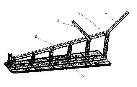
Some embodiments of the invention are provided with
the help of figures 1-8.
Figure 1 represents a configuration of the support
with a single framework.
Figure 2 represents a configuration of the support
with a multiple framework.
Figures 3 and 4 represent a front view of the same
previous configurations, after the laying of the pipeline
and after the lateral buckling of the pipeline itself, re-
spectively.
Figures 5 and 6 represent a front view of a configura-
tion with a constant tilting surface and a variable tilting
surface, respectively.
Figure 7 represents a front view of.-:a configuration in
which the final section of the upper surface of the support
is counter-inclined.
Figure 8 represents a front view of a configuration in
which the upper surface of the support consists of a suc-
cession of surfaces with varying inclinations alternating
with horizontal stretches.
The following numbers indicate:
(1) the base structure;
(2) the tilting upper surfaces;

CA 02555241 2006-08-03
WO 2005/080845 PCT/EP2005/001222
9
(3) the funnels;
(4) the fixed bumpers;
(5) the movable bumpers after the laying of the pipeline;
(Pi) the pipeline after laying;
(Pf) the pipeline after the triggering of the lateral buck-
ling;
(F) the seabed;
(C) the laying corridor;
(a) the inclination angle of the upper surface with respect
to the horizontal plane.
20

Representative Drawing
A single figure which represents the drawing illustrating the invention.
Administrative Status

2024-08-01:As part of the Next Generation Patents (NGP) transition, the Canadian Patents Database (CPD) now contains a more detailed Event History, which replicates the Event Log of our new back-office solution.

Please note that "Inactive:" events refers to events no longer in use in our new back-office solution.

For a clearer understanding of the status of the application/patent presented on this page, the site Disclaimer , as well as the definitions for Patent , Event History , Maintenance Fee  and Payment History  should be consulted.

Event History

Description Date
Time Limit for Reversal Expired 2016-02-04
Letter Sent 2015-02-04
Grant by Issuance 2012-07-24
Inactive: Cover page published 2012-07-23
Inactive: Final fee received 2012-05-07
Pre-grant 2012-05-07
Notice of Allowance is Issued 2011-12-07
Letter Sent 2011-12-07
Notice of Allowance is Issued 2011-12-07
Inactive: Approved for allowance (AFA) 2011-12-05
Inactive: Correspondence - MF 2010-08-10
Amendment Received - Voluntary Amendment 2010-05-06
Letter Sent 2010-01-26
Request for Examination Requirements Determined Compliant 2009-12-23
All Requirements for Examination Determined Compliant 2009-12-23
Request for Examination Received 2009-12-23
Inactive: IPRP received 2008-02-07
Letter Sent 2006-12-15
Inactive: Single transfer 2006-11-09
Inactive: Courtesy letter - Evidence 2006-10-03
Inactive: Cover page published 2006-10-02
Inactive: Notice - National entry - No RFE 2006-09-27
Application Received - PCT 2006-09-08
National Entry Requirements Determined Compliant 2006-08-03
Application Published (Open to Public Inspection) 2005-09-01

Abandonment History

There is no abandonment history.

Maintenance Fee

The last payment was received on 2012-01-20

Note : If the full payment has not been received on or before the date indicated, a further fee may be required which may be one of the following

  • the reinstatement fee;
  • the late payment fee; or
  • additional fee to reverse deemed expiry.

Please refer to the CIPO Patent Fees web page to see all current fee amounts.

Owners on Record

Note: Records showing the ownership history in alphabetical order.

Current Owners on Record
SAIPEM ENERGY INTERNATIONAL S.P.A.
Past Owners on Record
FLORIANO CASOLA
LUCA BRANDUARDI
PAOLO MONTI
Past Owners that do not appear in the "Owners on Record" listing will appear in other documentation within the application.
Documents

To view selected files, please enter reCAPTCHA code :


To view images, click a link in the Document Description column. To download the documents, select one or more checkboxes in the first column and then click the "Download Selected in PDF format (Zip Archive)" or the "Download Selected as Single PDF" button.

List of published and non-published patent-specific documents on the CPD .

If you have any difficulty accessing content, you can call the Client Service Centre at 1-866-997-1936 or send them an e-mail at CIPO Client Service Centre.


Document
Description 
Date
(yyyy-mm-dd) 
Number of pages   Size of Image (KB) 
Description 2006-08-03 9 301
Claims 2006-08-03 3 94
Abstract 2006-08-03 1 86
Drawings 2006-08-03 6 202
Representative drawing 2006-09-29 1 35
Cover Page 2006-10-02 1 65
Description 2010-05-06 9 309
Claims 2010-05-06 2 61
Cover Page 2012-06-28 1 67
Reminder of maintenance fee due 2006-10-05 1 110
Notice of National Entry 2006-09-27 1 192
Courtesy - Certificate of registration (related document(s)) 2006-12-15 1 106
Reminder - Request for Examination 2009-10-06 1 117
Acknowledgement of Request for Examination 2010-01-26 1 177
Commissioner's Notice - Application Found Allowable 2011-12-07 1 163
Maintenance Fee Notice 2015-03-18 1 170
PCT 2006-08-03 4 131
Correspondence 2006-09-27 1 28
Fees 2006-10-30 1 42
PCT 2006-08-04 6 214
Correspondence 2010-08-10 1 46
Correspondence 2011-12-07 1 87
Correspondence 2012-05-07 2 55