Note: Descriptions are shown in the official language in which they were submitted.
CA 02555710 2006-08-09
t
SPECIFICATION
SILENCER FOR PASSAGE
TECHNICAL FIELD
[0001] The present invention relates to a silencer for a
passage to be mounted in the passage through which gas or liquid
flows for reducing noises which are propagated through the
passage.
BACKGROUND OF THE INVENTION
[0002] A passage which allows gas or liquid to pass
therethrough propagates not only fluid but also noises and hence,
conventionally, there has been known a passage which mounts a
silencer for reducing the propagation of such noises thereon.
[0003] As a typical example, in an industrial plant or a
building which generates large noises, there has been a drawback
that these noises easily propagate through a duct. To reduce
such noises, in general, there has been used a duct silencer
which silences the noises by absorbing acoustic energy of the
noises using a sound absorbing member such as glass wool.
[0004] As one of duct silencers which uses the sound absorbing
member, Fig. 23 shows a splitter-type duct silencer X1 which
divides the inside of a duct D finely in the vertical direction
or in the lateral direction using partition walls 20 made of a
metal plate or the like, and mounts a sound absorbing member 21
on surfaces of the partition walls 20 or inner wall surfaces of
the duct D, while Fig. 24 shows a cell-type duct silencer X2
which finely divides the inside of the duct D into cells finer
than cells of the splitter-type duct silencer X1.
[0005] In these duct silencers X1 and X2, an arrangement area
of the sound absorbing member 21 is increased by partitioning
the inside of the duct D with the partition wall 20 thus
increasing a noise attenuation quantity. However, the above-
mentioned sound absorbing member 21 made of glass wool or the
1
CA 02555710 2006-08-09
like exhibits the poor silencing capacity at a low frequency
band and hence, it is difficult to prevent the propagation of
the noises at the low frequency band.
[0006] Accordingly, the inventor of the present invention has
proposed a duct silencer which is disclosed in Japanese Patent
Zaid-open No. 2003-216159 (patent document 1), wherein by
arranging a soft acoustic section soft in acoustics where a
sound pressure on an inner wall surface becomes substantially
zero is arranged on the inner wall surface, the propagation of
the noises in the low frequency band can be prevented. The soft
acoustic section is configured such that a plurality of acoustic
pipes having a length from an open end to a closed end thereof
disposed on inner wall surface of the duct equal to 1/4 of a
wavelength of a sound wave of noises (hereinafter referred to as
1/4 wavelength acoustic pipes) is arranged in parallel to each
other over a length more than approximately a half wave length
of the sound wave of noises in the longitudinal direction of the
duct.
[0007] In the conventional duct silencer which uses the 1/4
wavelength acoustic pipes, it is necessary to continuously
arrange the soft acoustic section over more than approximately a
half wave length of the sound wave of noises on the inner wall
surface of the duct. Accordingly, there exists a possibility
that in a predetermined region where the soft acoustic section
is formed, it is difficult to provide other constitution to the
duct. Accordingly, the constitution of the duct is restricted
or a region where the duct silencer can be mounted is limited.
[0008] Further, in the duct silencer which uses the 1/4
wavelength acoustic pipes, a silencing effect is difficult to
achieve unless an open width of the duct is equal to or less
than a half wavelength of the sound wave of noises. Accordingly,
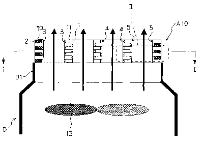
when the open width of the duct exceeds the half wavelength of
the sound wave of noises, it is necessary to divide the inside
of the duct by partition walls as in the case of the cell-type
2
CA 02555710 2006-09-08
or the splitter-type duct silencer. In this case, when the 1/4
wavelength acoustic pipes are arranged on the partition walls,
the partition walls become thick thus lowering an opening rate
with respect to a cross-sectional area of the duct.
[0009,] For example, in the cell-type duct silencer X2 shown in
Fig. 24, when the 1/4 wavelength acoustic pipes are arranged in
place of the sound absorbing member 21, as shown in Fig. 25(a),
assuming that an opening width "t" of one cell is A/2 of a
maximum value (~ being a wavelength of the sound wave), the
acoustic pipes having a length of ~/4 are arranged along four
peripheral surfaces of the cell. Accordingly, the total cross-
sectional area becomes 2A x 2~ = 4a2, wherein an area which
allows an air flow to pass therethrough becomes A/2 x A/2 x 4 =
A2. That is, the opening ratio becomes 1/4.
[0010] Further, even when the 1/4 wavelength acoustic pipes are
arranged on only two opposing surfaces around the periphery of
the cell as shown in Fig. 25(b), for example, the opening ratio
becomes 1/2.
[0011] In this, manner, when the 1/4 wavelength acoustic pipes
are applied to'the partition walls which divide the inside of
the duct, a more than half of the cross-sectional area of the
duct is occupied by the structural body. Accordingly, the air
permeability of the duct is lowered thus giving rise to a
possibility that it is difficult to use the 1/4 wavelength
acoustic pipes in an actual practice.
Patent document 1: Japanese Patent Publication No. 2003-216159
DISCLOSURE OF THE INVENTION
[0012] Here, according to a first aspect of the present invention,
on an inner wall surface of a passage, a soft acoustic section soft
in acoustics where a sound pressure at an inner wall surface of the
passage is approximately zero and a non-soft acoustic section where
a sound pressure at the inner wall surface of the passage is not
zero are alternately arranged over
3
CA 02555710 2006-09-08
more than approximately a half wavelength of a sound wave to be
silenced in a longitudinal direction of the passage.
[0013] Further, according to a second aspect of the present
invention, the passage is divided by partition walls such that an
opening width becomes a half wave length or less of the sound wave
to be silenced. On both side surfaces of the partition wall, the
soft acoustic section soft in acoustics where the sound pressure at
the inner wall surface of the passage is approximately zero and the
non-soft acoustic section where the sound pressure at the inner wall
surface of the passage is not zero are alternately arranged over
more than approximately a half wavelength of the sound wave to be
silenced in the longitudinal direction of the passage.
[0014] Further, according to a third aspect of the present
invention, in the first or second aspect, the soft acoustic section
is formed of an acoustic pipe having a length thereof from an open
end of the pipe disposed on a wall surface to a closed end equal to
1/4 of the wavelength of the sound wave to be silenced.
[0015] Further, according to a fourth aspect of the present
invention, in the third aspect, the acoustic pipe has the open end
thereof covered with a film.
[0016] Further, according to a fifth aspect of the present
invention, in the third or fourth aspect, the soft acoustic section
is formed by arranging an open end of the acoustic pipe on one wall
surface of the partition wall, and the non-soft acoustic section is
formed by arranging a closed end of the acoustic pipe on another
wall surface.
[0017] Further, according to a sixth aspect of the present
invention, in any one of the first to fifth aspects, the non-soft
acoustic section is formed of a sound absorbing member which reduces
a sound pressure.
4
CA 02555710 2006-09-08
[0018] Further, according to a seventh aspect of the present
invention, a first silencing means is mounted on one pair of inner
wall surfaces out of two pairs of oppositely facing inner wall
surfaces of the passage having a rectangular cross section, and a
second silencing means which has silencing property different from
silencing property of the first silencing means is mounted on
another pair of the inner wall surfaces. The first silencing means
is configured such that a soft acoustic section soft in acoustics
where the sound pressure at the inner wall surface of the passage is
approximately zero and a non-soft acoustic section where the sound
pressure at the inner wall surface of the passage is not zero are
alternately arranged over more than approximately a half wavelength
or more of the sound wave to be silenced in the longitudinal
direction of the passage.
[0019] Further, according to an eighth aspect of the present
invention, the passage is divided by the partition walls so as to
form a plurality of miniaturized passages having a rectangular cross
section in the passage such that an open width becomes a half
wavelength or less of the sound wave to be silenced. A first
silencing means is mounted on one pair of inner wall surfaces out of
two pairs of oppositely facing inner wall surfaces of the
miniaturized passage, and a second silencing means which has
silencing property different from silencing property of the first
silencing means is mounted on another pair of the inner wall
surfaces. The first silencing means is configured such that a soft
acoustic section soft in acoustics where the sound pressure at the
inner wall surface of the passage is approximately zero and a non-
soft acoustic section where the sound pressure at the inner wall
surface of the passage is not zero are alternately arranged over
more than approximately a half wavelength or more of the sound wave
to be silenced in the longitudinal direction of the passage.
5
CA 02555710 2006-09-08
[0020] Further, according to a ninth aspect of the present
invention, in the seventh or eighth aspect, the soft acoustic
section is formed of an acoustic pipe having a length from an open
end of the pipe disposed on a wall surface to a closed end equal to
1/4 of a wavelength of the sound wave to be silenced.
[0021] Further, according to a tenth aspect of the present
invention, in the ninth aspect, the acoustic pipe has the open end
thereof covered with a film.
[0022] Further, according to an eleventh aspect of the present
invention, in the ninth or tenth aspect, the soft acoustic section
is formed by arranging an open end of the acoustic pipe on one wall
surface of the partition wall, and the non-soft acoustic section is
formed by arranging a closed end of the acoustic pipe on another
wall surface.
[0023] Further, according to a twelfth aspect of the present
invention, in any one of the seventh to eleventh aspects, the second
silencing means is configured such that a sound absorbing section
which reduces a sound pressure of the sound wave to be silenced is
formed on the inner wall surface.
BRIEF EXPLANATION OF THE DRAWINGS
[0024] Fig. 1 is an explanatory view of a measuring device which
measures a silencing capacity of a duct silencer;
Fig. 2 is a perspective view showing an acoustic pipe arrangement
body of the duct silencer which becomes an object to be tested;
Fig. 3 is a perspective view showing an acoustic pipe arrangement
body of the duct silencer which becomes an object to be tested;
Fig. 4 is a perspective view showing an acoustic pipe
arrangement body of the duct silencer which becomes an object to be
3 0 tested;
6
CA 02555710 2006-09-08
Fig. 5 is an explanatoryview of the boundary surface
structure of the duct silencerwhich becomes an object to tested;
be
Fig. 6 is a graph showing result of measurement of
a the
silencing capacity of the silencer;
duct
Fig. 7 is a graph showing result of measurement of
a the
silencing capacity of the silencer;
duct
Fig. 8 is a graph showing result of measurement of
a the
silencing capacity of the silencer;
duct
Fig. 9 is an explanatory
view showing a
use state of one
embodiment of the duct silencer
in cross section;
Fig. 10 is an explanatory taken
view of a cross-sectional
shape
along a li ne I-I in Fig. 1;
Fig. 11 is an explanatory soft
view showing the
arrangement of
acoustic s ections and non-softacoustic sections in a regionII in
Fig. 1;
Fig. 12 is a perspective view showing one embodiment of the duct
silencer;
Fig. 13 is a perspective view showing the duct silencer of
another embodiment;
Fig. 14 is an explanatory view of the boundary surface structure
of the duct silencer which becomes an object to be tested;
Fig. 15 is an explanatory view of the boundary surface structure
of the duct silencer which becomes an object to be tested;
Fig. 16 is an explanatory view of a measuring device which
measures a silencing capacity of a duct silencer;
Fig. 17 is a graph showing a result of measurement of the
silencing capacity of the duct silencer;
Fig. 18 is a graph showing a result of measurement of the
silencing capacity of the duct silencer;
Fig. 19 is an explanatory view showing a use state of another
embodiment of the duct silencer in cross section;
7
CA 02555710 2006-09-08
Fig. 20 is an explanatory view of a cross-sectional shape taken
along a line III-III in Fig. 19;
Fig. 21 is an explanatory view showing the arrangement of soft
acoustic sections and non-soft acoustic sections in a region IV in
Fig. 19;
Fig. 22 is a graph showing a result of an experiment which
confirms advantageous effects when a film is mounted on an open
portion of an acoustic pipe;
Fig. 23 is an explanatory view of a conventional splitter-type
duct silencer;
Fig. 24 is an explanatory view of a conventional cell-type duct
silencer; and
Figs. 25(a) and 25(b) are explanatory views showing a state in
which a 1/4 wavelength acoustic pipe is arranged in the conventional
cell-type duct silencer, wherein Fig. 25(a> is an explanatory view
showing a state in which the 1/4 wavelength acoustic pipe is
arranged on four peripheral surfaces of the cell, and Fig. 25(b) is
an explanatory view in which the 1/4 wavelength acoustic pipe is
arranged on only two opposing peripheral surfaces of the cell.
BEST MODE FOR CARRYING OUT THE INVENTION
2'0 [0025] A silencer for a passage according to the present
invention is used in a state that the silencer for a passage is
mounted on a duct which performs intake and discharge of air and
a ventilation hole which performs ventilation. Here, in the
embodiments described hereinafter, as a typical embodiment of
the silencer for a passage according to the present invention, a
duct silencer which is mounted on a duct is explained. However,
it is needless to say that the present invention is not limited
to the duct silencer and is applicable to a silencer in general
which is mounted on a passage for a fluid such as a gas or a
liquid.
[0026] A duct silencer which constitutes one embodiment of the
silencer for a passage according to the present invention
includes a soft acoustic section soft in acoustics where a sound
pressure on an inner wall surface becomes substantially zero and
8
CA 02555710 2006-08-09
a non-soft acoustic section where the sound pressure at the
inner wall surface of the passage is not zero which are
alternately arranged over more than approximately a half
wavelength of a sound wave to be silenced in the length
direction of the passage.
[0027] That is, the above-mentioned duct silencer can be
mounted on the inside or on the outside of the duct, and when
the duct silencer is attached on the inside of the duct, a new
duct inner wall consisting of the soft acoustic section and t:he
non-soft acoustic section is formed at a position at which the
new inner wall of the duct projects toward the central side of
the duct than an original inner wall level of the duct, while in
case the duct silencer is attached on the outside of the duct, a
new duct inner wall consisting of the soft acoustic section and
the non-soft acoustic section is formed on the same level as the
original inner wall of the duct.
[0028] Here, it is preferable that the constitution which is
formed of the soft acoustic section and the non-soft acoustic
section is provided to at least a pair of oppositely facing
inner wall surfaces of the duct.
[0029] Further, the duct silencer is configured such that, in
so-called the cell-type or the splitter-type duct silencer which,
when the open width of the duct is larger than the wavelength of
the sound wave which becomes an object to be silenced
(hereinafter, referred to as an object sound wave), divides the
duct using partition walls so as to make the open rate to be a
half wavelength or less of the object sound wave, on both side
wall surfaces of the partition wall, the soft acoustic section
soft in acoustic where the sound pressure at the wall surface is
approximately zero and the non-soft acoustic section where the
sound pressure at the wall surface is not zero are alternately
arranged over more than approximately the half wavelength of the
sound wave to be silenced in the length direction of the duct.
9
CA 02555710 2006-08-09
[0030] Also by mounting the duct silencer at the partition wall,
a new wall surface is formed by the soft acoustic section and
the non-soft acoustic section of the duct silencer.
[0031] That is, when the duct silencer is mounted on the duct,
a predetermined region of the inner wall surface of the duct or
the wall surface of a partition wall is formed of the soft
acoustic section and the non-soft acoustic section of the duct
silencer.
[0032] The above-mentioned non-soft acoustic section includes a
sound absorbing acoustic section which has a function of
reducing a sound pressure, which is not zero, by using a sound
absorbing member such as a metallic fiber represented by glass
wool, rock-wool and aluminum fiber, a foamed aluminum, a ceramic
absorbing material or the like, a rigid acoustic section rigid
in acoustics which is made of a rigid body such as a metal plate
in the same manner as a duct and has no sound pressure reducing
function and the like. In the non-soft acoustic section, a
silencing function (a noise reduction function) is not a
prerequisite. For example, an original wall surface of the duct
may be used as the non-soft acoustic section.
[0033] Further, in the duct silencer, this non-soft acoustic
section and the soft acoustic section which has a silencing
function are alternately arranged on the inner wall surface of
the duct or on both-side wall surfaces of the partition wall.
That is, on the inner wall surface of the duct or on both-side
wall surfaces of the partition wall, the soft acoustic section
and the non-soft acoustic section are arranged in parallel to
each other in a checkered pattern or in a striped pattern.
[0034] In this manner, on the inner wall surface of the duct or
on both-side wall surfaces of the partition wall, not only the
soft acoustic section but also non-soft acoustic section are
arranged and hence, a region which is occupied by the soft
acoustic section which is to be constituted such that a sound
pressure thereof is zero can be reduced thus increasing a region
CA 02555710 2006-08-09
of the duct on which the duct silencer of the present invention
can be mounted.
[0035] Further, in the inside of the duct, not to mention that
the sound wave to be silenced can be silenced by the silencing
function of the soft acoustic section, by making use of the non-
soft acoustic section which is alternately arranged with the
soft acoustic section as either the sound absorbing acoustic
section or the rigid acoustic section as mentioned previously,
the duct silencer can be used for multi purposes.
[0036] Particularly, by assuming the above-mentioned non-soft
acoustic section as a sound absorbing acoustic section and by
forming the non-soft acoustic section using a sound absorbing
member such as a fiber material which can decrease the sound
pressure, it is possible not only to silence a sound wave in a
predetermined frequency band which is an object sound wave in
the soft acoustic section, but also to silence a sound wave in a
different predetermined band in the non-acoustic section, the
frequency band in which the sound wave can be silenced by the
silencer can be expanded so as to enhance the silencing effect
of the silencer.
[0037] Further, as mentioned above, by forming the wall surface
per se of the duct into the non-acoustic section, the use of new
constitution can be obviated and hence, the silencer becomes
light-weighted.
[0038] On the other hand, the soft acoustic section, to be more
specific, can be constituted of an acoustic pipe (a 1/4
wavelength acoustic pipe) having a length thereof from an open
end of the pipe disposed on a wall surface to a closed end set
to 1/4 of a wavelength of a sound wave which becomes the object
to be silenced. When the soft acoustic section is constituted
of such an acoustic pipe, by changing a length of the acoustic
pipe corresponding to a wavelength of a sound to be silenced, it
is possible to silence sounds having various wavelengths.
11
CA 02555710 2006-08-09
[0039] Further, the non-soft acoustic section may be formed
between the acoustic pipes which constitute the soft acoustic
section. Accordingly, even when the soft acoustic section is
occupied with the acoustic pipes, the non-soft acoustic section
may be provided as open spaces and hence, it is possible to use
these open spaces for other purposes. For example, when the
duct silencer is disposed outside the duct, the duct silencer is
mounted on a periphery of the duct in a projecting manner.
However, by making use of the non-soft acoustic section as the
open space, even in a narrow space such as an attic space or the
inside of a wall where many other wires, pipes and the like are
arranged, it is possible to broaden the possibility that the
duct silencer of the present invention can be installed.
[0040] Further, by mounting a film having a small resistance in
acoustics and as an extremely large resistance as a fluid on the
opening portion of the acoustic pipe, it is possible to
constitute the soft acoustic section using acoustic pipes which
are shorter than the above-mentioned 1/4 wavelength.
Accordingly, by covering the opening portion of the acoustic
pipe with a film made of plastic or the like, it is possible to
easily realize the miniaturization of the duct silencer, the
easy mounting of the duct silencer and the reduction of weight
of the duct silencer.
[0041] In this manner, when the opening part of the acoustic
pipes are closed with the film, it is possible to previously
prevent a generation of noises caused by an air flowing in the
inside of the duct collide to the open end of the acoustic pipes
so that the flow in the duct is disturbed.
[0042] Further, when the above-mentioned acoustic pipes are
applied to the partition walls which divide the inside of the
duct into a plurality of small ducts, it is possible to form the
soft acoustic section by arranging the open end of the acoustic
pipe on one wall surface of the partitions and to form the non-
soft acoustic section by arranging the closed end of the
12
CA 02555710 2006-08-09
acoustic pipe on another wall surface of the partitions. Due
to such a constitution, it is sufficient that the thickness of
the partition wall is set to a length of one acoustic pipe and
hence, the partition wall may be formed thin. Accordingly, even
when the duct is divided by the partition walls, an area where
the partition walls occupies in cross section of the duct can be
decreased as much as possible thus silencing the object sound
wave without lowering an air fluidity in the inside of the duct.
[0043] To arrange the soft acoustic section and the non-soft
acoustic section alternately as described above, even when the
soft acoustic section is not continuously provided over more
than approximately the half wavelength of the object sound wave
in the length direction of the duct, the object sound wave must
be silenced at the soft acoustic sections which are arranged at
a predetermined intervals within the above-mention half
wavelength. However, this evidence is certificated by a
comparative test that a silencing capacity of a duct silencer in
which the soft acoustic section is continuously provided and a
silencing capacity of a duct silencer in which the soft acoustic
section and the non-soft acoustic section are alternately
provided are compared with each other. Hereinafter, the
comparative test is explained in conjunction with the drawings.
[0044] In Fig. 1, a measuring device M which measures a
silencing capacity of the duct silencer is shown.
[0045] The measuring device M includes an acrylic-resin-made
duct D which has a square cross-sectional shape of lOcm(l0cm and
a length of 2m. A terminal end portion of the duct end D is
formed into a non-reflective end on which a sound absorbing
wedge M1 is mounted, a speaker M2 which constitutes a sound
source is mounted on a start end portion of the duct D opposite
to the non-reflective end, and a microphone M3 which collects
the sound outputted from the speaker M2 is mounted in front of
the above-mentioned sound absorbing wedge M1 which is arranged
closer to the non-reflective end side than the speaker M2.
13
CA 02555710 2006-08-09
[0046] Further, between the speaker M2 and the microphone M3,
that is, on a center portion of the duct D which is arranged
closer to the non-reflective end side than the speaker M2, a
duct silencer to be tested is mounted and hence, it may be
measured how much a sound outputted from the speaker M2 is
silenced by passing through the duct silencer.
[0047] Fig. 2 to Fig. 4 shows an acoustic pipe array which
constitutes the duct silencer A1 to A9 which have been tested in
this time.
[0048] The acoustic pipe array is constituted to set in array
the plural acoustic pipes in a perpendicular direction and/or a
horizontal direction and includes, a first acoustic pipe array 6
in which the acoustic pipes 1 (a 1/4 wavelength acoustic pipe)
made of aluminum which has a sectional shape of 5cm by 5cm and a
length of 1/4 of the wavelength of 1000Hz sound wave are
arranged in parallel in 2 rows and 10 columns as shown in Fig. 2
and is mounted in a state that a surface b (hereinafter,
referred to as a boundary surface) which is boundary with a
inner space of a duct D, that is, the inner wall surface of the
duct D becomes a opening portions of the first acoustic pipe 1,
a second acoustic pipe array 7 in which the openings of the
acoustic pipes of even number rows or odd number rows out of the
first acoustic array 6 are all closed by a rigid body 2 such as
a aluminum plate as shown in Fig. 3, a third acoustic pipe array
8 in which glass wool of a sound absorbing member 3 is adhered
on to the rigid body 2 which closes the openings of the acoustic
pipe 1 of the second acoustic pipe array 7, a fourth acoustic
pipe array 9 in which the openings of the acoustic pipe 1 of the
first acoustic pipe array 6 are alternately closed by the
aluminum plates in a checkered pattern as shown in Fig. 4 and,
at the same time, glass wool of a sound absorbing member 3 is
adhered on to the rigid body.
[0049] That is, the above-mentioned first to fourth acoustic
pipe array 6, 7, 8, 9 are designed so as to set a frequency to
14
CA 02555710 2006-08-09
be silenced 1000 Hz, particularly, the first acoustic pipe array
6 has the soft acoustic section over all the boundary surface b
which has the length of half wavelength of the frequency to be
silenced or more, the second and third acoustic pipe array 7, 8
has the soft acoustic section and the non-soft acoustic section
which is arranged in a striped pattern over all the boundary
surface b which has the length of half wavelength of the
frequency to be silenced or more, the fourth acoustic pipe array
9 has the soft acoustic section and the non-soft acoustic
section which is arranged in a checkered pattern over all the
boundary surface b which has the length of half wavelength of
the frequency to be silenced or more. And in this comparative
test, by combining a plurality of the above-mentioned first to
fourth acoustic pipe array 6, 7, 8, 9, the 9 types of the
silencer (the first to fourth silencer A1 to A9) are formed.
[0050] Fig. 5 shows a boundary surface structure of the
acoustic pipe array in the respective silencer A1 to A9. As
shown in the drawings, the first silencer to the sixth silencer,
A1 to A6 consists of two acoustic pipe arrays mounted on the
left wall and the right wall of the duct D, while the seventh
silencer to the ninth silencer, A7 to A9 consists of four
acoustic pipe arrays mounted on the left wall, the right wall,
the top wall and the bottom wall of the duct D. In the drawings,
a "matted triangle" indicates a start end side (the side on
which a speaker M2 is mounted) of the duct D.
[0051] In Fig. 6 to Fig. 8, a result of the measured silencing
ability of the first silencer to the ninth silencer, A1 to A9 is
shown. Here, in Fig. 6 to Fig. 8, on an axis of ordinates, a
sound volume (dB) of the sound wave is taken as an attenuation
quantity from the reference value, wherein the silencers A1 to
A9 are not mounted thus allowing the whole inner wall surface of
the duct D to be a rigid body 2, in which by setting the sound
volume (dB) of the sound wave collected by a microphone M3 as
CA 02555710 2006-08-09
the reference value, the sound volume of the sound wave is
collected when the respective silencers A1 to A9 are mounted.
Further, an axis of abscissas is a frequency axis which shows
the band between 300 Hz to 3000 Hz.
[0052] Fig. 6 shows a measurement result of the silencers A2,
A3 and A4 in the second and the third acoustic pipe arrays 7 and
8 in which the boundary surface b is arranged in the form of
strips are mounted on an opposing pair of surfaces of the duct D.
[0053] A solid line, as shown in Fig. 5, indicates a result of
measuring the first silencer A1 as a comparison example, wherein
the first acoustic pipe array 6 whose boundary surface b is
totally the soft acoustic section 4 is mounted on a pair of
opposing surfaces of the duct D and exhibits a sound reducing
effect equal to or more than 40 dB in a range approximately
between 850 Hz to 1200 Hz centering on 1000 Hz.
[0054] An alternate long and short dash line, as shown in Fig.
5, indicates a result of measuring the second silencer A2,
wherein the boundary surface structure of an opposing pair of
the second acoustic pipe array 7 coincide with each other such
that the soft acoustic section 4 to the soft acoustic section 4
and the non-soft acoustic section 5 to the non-soft acoustic
section 5. Although the sound reducing effect of the silencer
A2 is approximately the same as the sound reducing effect of the
first silencer Al, the frequency band which indicates the sound
reducing effect is shifted toward the low frequency in the
second silencer A2.
[0055] An alternate long and double-short dash line, as shown
in Fig. 5, indicates a result of measuring the third silencer A3,
wherein another acoustic pipe array opposing to the second
acoustic pipe array 7 is the first acoustic pipe array 6 and the
upper limit of the frequency band in which the sound reducing
effect is seen is a little higher than the upper limit of the
frequency band of the second silencer A2.
16
CA 02555710 2006-08-09
[0056] A dashed line, as shown in Fig. 5, indicates a result of
measuring the fourth silencer A4, wherein the boundary surface
structures of the opposing pair of the third acoustic pipe array
8 coincide to each other and the sound reducing effect before
and after 1000 Hz which is a determined frequency to be silenced
does not show any changes whereas a large attenuation
(approximately 15 dB) is obtained at a higher frequency band.
This is an effect of the sound absorbing member 3.
[0057] Fig. 7 shows the result of measuring the silencers A5
and A6, wherein the fourth acoustic pipe array 9 in which the
boundary surface b includes the soft acoustic section 4 and the
non-soft acoustic section 5 extracted in a checkered pattern
with each other is mounted on one opposing pair of the surfac=.e
of the duct D.
[0058] In Fig. 7, as a comparison example, the results of
measuring the first silencer A1 and the fourth silencer A4 which
are explained in the above-mentioned Fig. 6 is shown. The solid
line indicates the result of measuring the first silencer A1 and
the alternate long and double-short dash line indicates the
result of measuring the fourth silencer A4.
[0059] The dashed line, as shown in Fig. 5, indicates the
result of measuring the fifth silencer A5, wherein the boundary
surface structures of the opposing pair of the fourth acoustic
pipe array 9 coincide to each other, and the upper limit of the
frequency band in which the sound reducing effect is seen is
approximately the same as in the above-mentioned fourth silencer
A4, however, the lower limit of the frequency band exhibits a
little higher in the fifth silencer A5. Further, in case of the
fifth silencer A5, although it is not an obvious sound reducing
effect, in the frequency band equal to 1000 Hz or less which is
a frequency band to be silenced, a certain degree of sound
reducing effect can be seen.
[0060] The alternate long and snort dash line indicates the
result of measuring the sixth silencer A6, wherein different
17
CA 02555710 2006-08-09
from the fifth silencer A5, an opposing pair of the boundary
surface structure of the third acoustic pipe array 8 includes
the soft acoustic section 4 and the non-soft acoustic section 5
which are inconsistent to each other. In comparing the sixth
silencer A6 to the fifth silencer A5, although the frequency
band in which the sound reducing effect appears is approximately
the same as in the fifth silencer A5, by eliminating before and
after 1000 Hz which is the frequency to be silenced, as a whole,
the sound reducing effect of the sixth silencer A6 is lower than
the sound reducing effect of the fifth silencer A5.
[0061] Fig. 8 shows results of measurement of the silencers A8,
A9 which mount fourth acoustic pipe array 9 which have boundary
surfaces b formed into a checkered pattern consisting of the
soft acoustic section 4 and the non-soft acoustic section 5 on
whole four surfaces of the duct D.
[0062] As shown in Fig. 5, a solid line indicates, as a
comparison example, a result of a measurement of a seventh
silencer A7 which mounts the first acoustic array 6 in which
whole boundary surface b is formed of the soft acoustic section
4 on all four surfaces of the duct D. The result shows that
the seventh silencer A7 exhibits the substantially same sound
reducing effect of equal to or more than 40 dB around 1000 Hz as
the above-mention first silencer A1.
[0063] As shown in Fig. 5, a dotted line indicates a result of
a measurement of the eighth silencer A8 in which the boundary
surface structures of the two facing fourth acoustic arrays 9
agree to each other in the respective two pairs of oppositely
facing fourth acoustic arrays 9. Here, when the result the
measurement of the eighth silencer A8 is compared with the
result of the measurement of the seventh silencer A7, a
frequency range in which the sound reducing effect of equal to
or more than 40 dB around 1000 Hz is viewed is narrowed.
Further, although a silencing effect appears even in a frequency
18
CA 02555710 2006-08-09
range of 1000 Hz to 2000 Hz, the silencing effect is not so
large, that is, an approximately 10 dB.
[0064] A chain line indicates a result of a measurement of the
ninth silencer A9 in which the boundary surface structures of
the two facing fourth acoustic arrays 9, different from the
eighth silencer A8, do not agree to each other in the respective
two pairs of oppositely facing fourth acoustic arrays 9. The
result shows that also a large sound reducing effect appears
around 1000 Hz which is a frequency of the object to be silenced,
and the result also shows that a large sound reducing effect of
30 dB is obtained in the vicinity of 2000 Hz.
[0065] According to the results of the measurement shown in Fig.
6 to 8, even when the soft acoustic section 4 is not arrange~~
over more than approximately a half wavelength or more of the
object sound wave (here, 1000 Hz) in the length direction of the
duct, by the non-soft acoustic section 5 and the soft acoustic
section 4 which are alternately arranged with each other between
the half wavelengths, it is possible to obtain a silence
function equal to a silence function which is obtained by
arranging the soft acoustic section 4 continuously.
[0066] Further, when the non-soft acoustic section 5 is
constituted of a sound absorptive acoustic section which is
formed of the sound absorbing member 3, in addition to the
silence function of the soft acoustic section 4, a silence
function due to the sound absorptive acoustic section is
operated and hence, it is possible to broaden a frequency band
in which the silencing effect appears.
[0067] Next, an embodiment of a duct silencer is explained in
detail in conjunction with drawings. Here, in the following
explanation, the embodiment is explained when the duct silencer
is applied to a cell type duct silencer.
[0067] Next, an embodiment of a duct silencer is explained in
detail in conjunction with drawings. Here, in the following
19
CA 02555710 2006-08-09
explanation, the embodiment is explained when the duct silencer
is applied to a cell type duct silencer.
[0068] Fig. 9 is an explanatory view in a sectional direction
showing an embodiment of the duct silencer in a state of
operation, Fig. 10 is a cross-sectional explanatory view of Fig.
1 as viewed from a line I-I, and Fig. 11 is an explanatory view
of Fig. 1 showing an arrangement of the soft acoustic section 4
and the non-soft acoustic section 5 in a region II.
[0069] As shown in the drawings, the duct silencer A10 of this
embodiment is mounted on an exhaust port D1 portion of a
rectangular-shaped duct D as viewed in a sectional direction
which constitutes a cooling tower for air conditioning, and
includes acoustic pipe arrays for a duct 10 which is
respectively arranged on a pair of opposed inner wall surfaces
of the duct D, acoustic pipe arrays for partition walls which
constitute three longitudinal partition walls which partition
the duct in a longitudinal direction and three lateral partition
wall 12 which partition the duct in a lateral direction. In the
drawing, numeral 13 indicates a blower.
[0070] The acoustic pipe arrays for duct walls 10 are formed in
a plate shape by arranging 1/4 wavelength acoustic pipes 1 made
of aluminum having a rectangular cross-sectional shape with one
closed end whereas another opened end in parallel along the duct
wall in a perpendicular direction and a horizontal direction and,
at the same time, the openings of the acoustic pipe 1 are
alternately closed by rigid bodies 2 such as aluminum plates and
sound absorbing members 3 made of glass wool are adhered on to
the rigid bodies 2 in a state that the closed end or the opened
end is not continuously arranged between two adjacent 1/4
wavelength acoustic pipes 1. As shown in Fig. 11, boundary
surfaces b which is boundary with an inner space of a duct D,
that is, the inner wall surfaces of the duct D are constituted
of the openings (soft acoustic section 4) of the acoustic pipes
1 and the sound absorbing members 3 (non-soft acoustic section
CA 02555710 2006-08-09
5) which are adhered on to the rigid bodies 2 in a checkered
pattern.
[0071] On the other hand, the acoustic pipe array for a
partition wall 11 is formed in a plate shape by alternately
arranging 1/4 wavelength acoustic pipes 1 made of aluminum
having a rectangular cross-sectional shape with one closed end
whereas another opened end in parallel in a perpendicular
direction and a horizontal direction in a state that the closed
end or the opened end is not continuously arranged between two
adjacent 1/4 wavelength acoustic pipes 1, and in this embodiment,
the acoustic pipe array for a partition wall 11 is constitutes a
longitudinal partition wall as it is.
[0072] That is, the acoustic pipe array for a partition wall. 11
is constituted in a state that front-back both surfaces
constitute boundary surfaces b which is boundary with an inner
space of a duct D, and the acoustic pipe 1 which the opening
portion thereof is arranged on the one boundary surface b is
constituted in a state that the closed portion thereof is
arranged on another boundary surface b. Further, the sound
absorbing members 3 made of glass wool is adhered on to the
above-mentioned closed portion, and in the boundary surface b, b
of the front-back both sides of the acoustic pipe array for a
partition wall 11, as shown in Fig. 11, the opening portion of
the acoustic pipe 1 and the sound absorbing members 3 (the non-
soft acoustic section 5) of the closed portion are formed in a
checkered pattern.
[0073] Here, the above-mentioned acoustic pipe array for a duct
wall 10 and acoustic pipe array for a partition wall 11 are
arranged over the length of half wavelength or more of the sound
wave to be silenced in a longitudinal direction.
[0074] Further, the lateral partition wall 12 includes the
rigid body 2 such as an aluminum plate, and is partitioned by
the lateral partition 12 and the acoustic pipe array for a
partition wall 11 which constitutes the above-mentioned
21
CA 02555710 2006-08-09
longitudinal partition wall in a state that the opening width t
of the duct D is a dimension of the half wavelength or less.
[0075] In this manner, in the duct silencer A10 according to
this embodiment, since the opening portion of the acoustic pipe
1 is constituted of the soft acoustic section 4 and, at the same
time, the closed portion is constituted of the non-soft acoustic
section 5, in the partition wall 11 (the acoustic pipe array for
a partition wall 11), the acoustic pipe 1 which constitutes the
soft acoustic section 4 on one boundary surface b constitutes
the non-soft acoustic section 5 on another boundary surface b.
Therefore, a thin partition wall 11 (the acoustic pipe array for
a partition wall 11) can be formed along with the silencing
function, and a noise which is propagated in the duct D can be
silenced without lowering a exhaust performance from the duct D.
[0076] Further, since noises can be absorbed by adhering the
sound absorbing member 3 on to the non-soft acoustic section 5,
in addition to a frequency band which can be silenced by the
soft acoustic section 4, other frequency band can also be
silenced at the non-soft acoustic section 5, and the duct
silencer A10 which has high silencing effect can be obtained.
[0077] Further, in the duct having a rectangular cross-
sectional shape of the duct silencer, in view of a point that
influences which are given to a noise propagation from two pairs
of oppositely facing inner wall surfaces are independent with
each other, a first silencing means is mounted on one pair of
inner wall surfaces and, at the same time, a second silencing
means which has silencing property different from silencing
property of the first silencing means may be mounted on another
pair of inner wall surfaces.
[0078] Furthermore, when a dimension of the opening width of
the duct is longer than the wavelength of the sound wave to be
silenced (hereinafter referred to as sound wave to be silenced),
the duct is divided by partition walls so as to form a plurality
of miniaturized ducts having a rectangular cross sectional shape
22
CA 02555710 2006-08-09
in the duct such that an opening width becomes a half wavelength
or less of a sound wave to be silenced as so-called a cell-type
or a splitter-type duct silencer, a first silencing means is
mounted on one pair of inner wall surfaces out of two pairs of
oppositely facing inner wall surfaces of the miniaturized ducts
and, at the same time, a second silencing means which has
silencing property different from silencing property of the
first silencing means may be mounted on another pair of inner
wall surfaces.
[0079] The above-mentioned silencing property suggests a
frequency band which can be silenced by the respective silencing
means and a damping of the sound wave which is then silenced.
In this manner, by using two type of the silencing means which
has different silencing property with each other, the sound wave
of the different frequency band can be silenced by respective
silencing means and the frequency band which can be silenced can
be broadened. Particularly, as the first silencing means and
the second silencing means, by combining two silencing means
which has different silencing mechanism with each other, the
more broadened frequency band can be silenced.
[0080] As this two type of the silencing means, a first
silencing means which is constituted in a state that a soft
acoustic section soft in acoustics where a sound pressure on an
inner wall surface becomes substantially zero is formed over
more than approximately a half wavelength of a sound wave to be
silenced in the length direction of the duct and a second
silencing means which is constituted in a state that sound
absorbing portions for reducing the sound pressure of the sound
wave to be silenced are formed on the inner wall surfaces can be
combined. By adopting the above-mentioned constitution, the
sound wave of the exclusive frequency band which constitutes the
main component of the noise can be silenced by the first
silencing means and, at the same time, the sound wave of the
more broadened frequency band which is not silenced by the first
23
CA 02555710 2006-08-09
silencing means can be silenced by the second silencing means so
as to effectively reduce the noise.
[0081] Here, the above-mentioned duct silencer can be mounted
on the inside or on the outside of the duct, and when the duct
silencer is attached on the inside of the duct, a new duct inner
wall consisting of the soft acoustic section and a sound
absorbing portion is formed at a position at which the new inner
wall of the duct projects toward the central side of the duct
than an original inner wall level of the duct, while in case the
duct silencer is attached on the outside of the duct, a new duct
inner wall consisting of the soft acoustic section and a sound
absorbing portion is formed on the same level as the original
inner wall of the duct.
[0082] The soft acoustic section which is formed by the first
silencing means, to be more specific, may be constituted of the
acoustic pipe (a 1/4 wavelength acoustic pipe) having a length
thereof from the open end of the pipe disposed on the inner wall
surface to the closed end set to 1/4 of a wavelength of a sound
wave which becomes the object to be silenced. When the soft
acoustic section is constituted of such an acoustic pipe, by
changing a length of the acoustic pipe corresponding to a
wavelength of a sound to be silenced, it is possible to silence
sounds having various wavelengths.
[0083] Further, by mounting a film having a small resistance in
acoustics and as an extremely large resistance as a fluid on the
opening portion of the acoustic pipe, it is possible to
constitute the soft acoustic section using acoustic pipes which
are shorter than the above-mentioned 1/4 wavelength.
Accordingly, by covering the opening portion of the acoustic
pipe with a film made of plastic or the like, it is possible to
easily realize the miniaturization of the duct silencer, the
easy mounting of the duct silencer and the reduction of weight
of the duct silencer. Further, in this manner, when the
opening part is sealed by providing the film to the opening part
24
CA 02555710 2006-08-09
of the acoustic pipes, it is possible to reduce an air flowing
sound caused by an air flowing thus broadening a noise reducing
frequency band.
[0084] Further, besides forming the first silencing means by
continuously providing the soft acoustic section soft in
acoustics where the sound pressure on the inner wall surface
becomes substantially zero as described above, it is also
possible to form the first silencing means by alternately
forming the soft acoustic section and the non-soft acoustic
section where the sound pressure at the inner wall surface of
the passage is not zero over more than approximately a half
wavelength of a sound wave to be silenced in the length
direction of the duct so as to become a checkered pattern or in
a striped pattern. In this case, the region which is occupied
by the soft acoustic section which is to be constituted such
that the sound pressure thereof is zero can be reduced thus
increasing a region of the duct on which the duct silencer can
be mounted.
[0085] Particularly, the above-mentioned non-soft acoustic
section can be a sound absorbing acoustic section which has a
function of reducing a sound pressure, which is not zero, by
using a sound absorbing member such as a metallic fiber
represented by glass wool, rock-wool and aluminum fiber, a
foamed aluminum, a ceramic absorbing material or the like, a
rigid acoustic section rigid in acoustics which is made of a
rigid body such as a metal plate in the same manner as a duct
and has no sound pressure reducing function and the like. In
the non-soft acoustic section, a silencing function (a noise
reduction function) is not a prerequisite. For example; an
original wall surface of the duct may be used as the non-soft
acoustic section. Accordingly, by constituting the first
silencing means such that the soft acoustic section and the non-
soft acoustic section are alternately formed, in the inside of
the duct, not to mention that the sound wave to be silenced can
CA 02555710 2006-08-09
be silenced by the silencing function of the soft acoustic
section, by making use of the non-soft acoustic section which is
alternately arranged with the soft acoustic section as either
the sound absorbing acoustic section or the rigid acoustic
section as mentioned previously, the duct silencer can be used
for multi purposes.
[0086] Further, by assuming the above-mentioned non-soft
acoustic section as a sound absorbing acoustic section and by
forming the non-soft acoustic section using a sound absorbing
member such as a fiber material which can decrease the sound
pressure, it is possible not only to silence a sound wave in a
predetermined frequency band which is an object sound wave in
the soft acoustic section, but also to silence a sound wave in a
different predetermined band in the non-acoustic section, the
frequency band in which the sound wave can be silenced in the
silencer can be expanded so as to enhance the silencing effect
of the silencer.
[0087] On the other hand, as mentioned above, by forming the
wall surface per se of the duct into the non-acoustic section,
the new structure can be obviated whereby the silencer becomes
light-weighted.
[0088] Further, also when the soft acoustic section is
constituted of the acoustic pipe, the non-soft acoustic section
is formed between the acoustic pipes which constitute the soft
acoustic section and hence, even when the soft acoustic section
is occupied with the acoustic pipes, the non-soft acoustic
section may be provided as open spaces thus using these open
spaces for other purposes. For example, when the non-soft
acoustic section is provided as open spaces, it is possible to
arrange a portion of the acoustic pipe at a position close to
the non-soft acoustic section by bending the acoustic pipe at a
midst portion thereof. In this case, it is possible to realize
the miniaturization of the duct silencer compared with a case
that the acoustic pipe extends straight. Accordingly, it is
26
CA 02555710 2006-08-09
possible to broaden the possibility that the duct silencer of
the present invention can be installed.
[0089] Further, when the above-mentioned acoustic pipes are
applied to the partition walls which divide the inside of the
duct into a plurality of small ducts, it is possible to form the
soft acoustic section by arranging the open end of the acoustic
pipe on one wall surface of the partitions and to form the non-
soft acoustic section by arranging the closed end of the
acoustic pipe on another wall surface of the partitions. Due
to such a constitution, it is sufficient that the thickness of
the partition wall is set to a length of one acoustic pipe and
hence, the partition wall may be formed thin. Accordingly, even
when the duct is divided by the partition walls, an area where
the partition walls occupies in cross section of the duct can be
decreased as much as possible thus silencing the object sound
wave without lowering an air fluidity in the inside of the duct.
[0090] On the other hand, a sound absorbing section which is
formed of a second silencing means, to be more specific, may be
constituted of a sound absorbing member such as a metallic fiber
represented by glass wool, rock-wool and aluminum fiber, a
foamed aluminum, a ceramic sound absorbing material or the like.
Here, by forming the sound absorbing section using such a sound
absorbing member, it is possible to silence the sound wave in a
broad frequency band, to be more specific, in a high frequency
band. Further, with the use of a non-fiber material such as the
above-mentioned ceramic sound absorbing material as a material
of the sound absorbing member, it is possible to overcome a
drawback related to a scattering of a material which has been
considered as a problem to be overcome conventionally.
[0091] Hereinafter, specific embodiments of the duct silencer
are explained in conjunction with drawings.
[0092] Fig. 12 shows a first duct silencer A11 which
constitutes one embodiment of the duct silencer.
27
CA 02555710 2006-08-09
[0093] The first duct silencer A11 is a duct silencer for an
experiment which is designed to measure a silencing ability
thereof. The first duct silencer A11 is constituted of a pair
of left and right first acoustic pipe arrays 37 which
constitutes first silencing means and a pair of upper and lower
sound absorbing members 33 which constitutes second silencing
means and is formed into a cylindrical shape with an inner space
having a square cross sectional shape of 10 cm x 10 cm and a
length of 50 cm.
[0094] The above-mentioned first acoustic pipe array 37 is
constituted to set in array the plural acoustic pipes in a
perpendicular direction and/or a horizontal direction, and is
configured such that the acoustic pipes (a 1/4 wavelength
acoustic pipe) 1 made of aluminum having a sectional shape of 5
cm by 5 cm and a length of 85mm which is 1/4 of the wavelength
of 1000 Hz are arranged in parallel in 2 rows and 10 columns and
is mounted in a state that a surface b (hereinafter, referred to
as a boundary surface) which is boundary with a inner space of a
duct D', that is, the inner wall surface of the duct D' becomes
a opening portions of the first acoustic pipe 31.
[0095] Further, the sound absorbing member 33 is made of plate-
like glass wool having a thickness of 50 mm and density of 32
kg/m3 and forms a sound absorbing section 36 which extends toward
an inner space of a duct D'. Furthermore, an outer peripheral
portion of the sound absorbing member 33 which does not face the
inner space of the duct D3 is covered with a casing 14 made of
an acrylic plate having a thickness of 20 mm thus preventing
leaking of noises to the outside of the duct D' from the inside
of the duct D' and, at the same time, preventing the intrusion
of noises to the inside of the duct D' from the outside of the
duct D'.
[0096] Further, Fig. 13 shows a second duct silencer A12 which
constitutes another embodiment.
28
CA 02555710 2006-08-09
[0097] The second duct silencer A12 is also a duct silencer for
experiment which is designed on a premise that a silencing
ability of the silencer A12 is measured and differs from the
above-mentioned first duct silencer A11 only with respect to the
constitution of the acoustic pipe array. That is, in the second
duct silencer A12, among the acoustic pipes 31 of the first
acoustic pipe array 37, opening portions of the acoustic pipes
3l of the above-mentioned first acoustic pipe array 37 are
closed by a rigid body 32 such as an aluminum plate in a
checkered pattern such that the neighboring acoustic pipes 31 do
not open continuously and, at the same time, the second acoustic
pipe array 38 which adheres glass wool constituting the sound
absorbing member 33 to the rigid body.
[0098] In this manner, in both of the first duct silencer A11
and the second duct silencer A12, the acoustic pipe array is
designed by setting the silencing object frequency to 1000 Hz,
wherein the first acoustic pipe array 37 of the first duct
silencer A11 has an all boundary surface b thereof formed into a
soft acoustic section 34 over a half wave length of the
silencing object frequency, while the second acoustic pipe array
38 of the second duct silencer A12 has a boundary surface b
thereof formed into a checkered pattern made of the soft
acoustic sections 34 and the non-soft acoustic section 35 over a
half wave length of the silencing object frequency.
[0099] Here, in the above-mentioned first duct silencer A11 and
the second duct silencer A12, the acoustic pipes 31 are made of
aluminum and the sound absorbing members 33 are made of glass
wool. However, the first duct silencer A11 and the second duct
silencer A12 are provided exclusively as duct silencing devices
for experiments. That is, the duct silencers are not limited to
these materials and materials which can constitutes the soft
acoustic section 34 and the sound absorbing section 36 can be
properly used. Further, the shape of the acoustic pipe 31 is
not limited to a rectangular cross section and the acoustic pipe
29
CA 02555710 2006-08-09
31 has any cross-sectional shape provided that the acoustic pipe
31 is formed in a cylindrical shape. Further, the constitution
of the acoustic pipe array and the thickness of the sound
absorbing member 33 may be also properly adjusted. Still
further, in the second duct silencer A12, two opposing second
acoustic pipe arrays 38 may also be configured such that the
soft acoustic sections 34 face each other and the non-soft
acoustic sections 35 face each other or may be constituted such
that the soft acoustic section 34 and the non-soft acoustic
section 35 face each other.
[0100] The above-mentioned first duct silencer AS11 and the
second duct silencer A12 are compared with a duct silencer which
is provided with only the first silencing means and a duct
silencer which is provided with only the second silencing means
with respect to the silencing ability.
[0101] Fig. 14 shows the boundary surface structure of the
first duct silencer A11 and the boundary surface structures of a
third duct silencer A13 and a fifth duct silencer A15 which
constitute comparison examples of the first duct silencer A11.
The third duct silencer A13 is constituted such that the first
acoustic pipe array 37 which constitutes the first silencing
means is provided to the portion where the sound absorbing
member 33 which constitutes the second silencing means is
provided in the first duct silencer A11 thus forming all 4
surfaces which face the inner space of the duct D' using only
the first silencing means, while the fifth duct silencer A15 is
constituted such that the sound absorbing member 33 which
constitutes the second silencing means is provided to portions
where the first acoustic pipe array 37 which constitutes the
first silencing means in the above-mentioned first duct silencer
A11 are provided thus forming all 4 surfaces which face the
inner space of the duct D' using only the second silencing means.
[0102] Fig. 15 shows the boundary surface structure of the
second duct silencer A12 and the boundary surface structures of
CA 02555710 2006-08-09
a fourth duct silencer A14 and a fifth duct silencer A15 which
constitute comparison examples of the second duct silencer A12.
The fourth duct silencer A14 is constituted such that the second
acoustic pipe array 38 which constitutes the first silencing
means is provided to the portion where the sound absorbing
member 33 which constitutes the second silencing means is
provided in the second duct silencer A12 thus forming all 4
surfaces which face the inner space of the duct D' using only
the first silencing means, while the fifth duct silencer A15 is
constituted such that the sound absorbing member 33 which
constitutes the second silencing means is provided to portions
where the second acoustic pipe array 38 which constitutes the
first silencing means in the above-mentioned second duct
silencer A12 are provided thus forming all 4 surfaces which face
the inner space of the duct D' using only the second silencing
means as explained in conjunction with Fig. 14.
[0103] Further, in Fig. 16, a measuring device M' which
measured silencing capacities of the above-mentioned first to
fifth duct silencers A11 to A15 is shown.
[0104] The measuring device M' includes an acrylic-resin-made
duct D' which has a square cross-sectional shape of 10 cm x 10
cm and a length of 2 m. A terminal end portion of the duct end
D' is formed into a non-reflective end on which a sound
absorbing wedge M'1 is mounted, a speaker M'2 which constitutes
a sound source is mounted on a start end portion of the duct D'
opposite to the non-reflective end, and a microphone M'3 which
collects the sound outputted from the speaker M'2 is mounted in
front of the above-mentioned sound absorbing wedge M'1 which is
arranged closer to the non-reflective end side than the speaker
M'2.
[0105] Further, between the speaker M'2 and the microphone M'3,
that is, on a center portion of the duct D' which is arranged
closer to the non-reflective end side than the speaker M'2, the
above-mentioned first to fifth duct silencers A11 to A15 to be
31
CA 02555710 2006-08-09
tested are mounted and hence, it may be measured how much a
sound outputted from the M'2 is silenced by passing through the
duct silencer. Here, a "closed triangle" shown in Fig. 14 and
Fig. 15 indicates a direction to be a start end side (the side
on which a speaker M2 is mounted) of the duct D at the time of
mounting the duct silencer on the measuring device M'.
[0106] Fig. 17 shows a result of measurement of the silencing
ability of the above-mentioned first duct silencer A11 and the
silencing abilities of the third duct silencer A13 and the fifth
duct silencer A15 which are comparison examples of the first
duct silencer A11. Here, in Fig. 17, an axis of ordinates
indicates sound volumes (dB) of sound waves which are collected
when the respective duct silencers A11, A13 and A15 are mounted
as an attenuation quantity (dB) from a reference value, wherein
a volume (dB) of a sound wave which is collected by the
microphone M'3 when the first duct silencer A11 is not mounted
and all inner wall surfaces of the duct D' is formed of a rigid
body 32 as the reference value. Further, an axis of abscissas
indicates the frequency (Hz) of the sound wave collected by the
microphone M'3 within a range from 315 Hz to 3000 Hz.
[0107] A solid line indicates, as shown in Fig. 14, a result of
the measurement of the first duct silencer A11. The solid line
implies that a large attenuation quantity of 40 dB or more is
obtained in a frequency band from approximately 800 Hz to
approximately 1800 Hz with 1000 Hz which is designed frequency
of the 1/4 wave length acoustic pipe 31 as the center of the
frequency band and a silencing effect is obtained in a
relatively broad frequency band covering one octave.
[0108] On the other hand, a chained line indicates, as shown in
Fig. 14, a result of the measurement of the third duct silencer
A13 which is constituted only of the first acoustic pipe array
37. To compare the measurement result of the third duct
silencer A13 and the measurement result of the first duct
silencer A11, in all frequency bands, the above-mentioned first
32
CA 02555710 2006-08-09
duct silencer A11 can obtain the greater attenuation quantity.
Particularly, on the high frequency bans side above 1600Hz, the
difference of silencing effect is increased.
[0109] Further, a dotted line indicates, as shown in Fig. 14, a
result of measurement of the fifth duct silencer A15 which is
constituted of only the sound absorbing member 33. To compare
the measurement result of the fifth duct silencer A15 with the
measurement result of the first duct silencer All, it is
understood that the first duct silencer A11 can obtain the
extremely large attenuation quantity within a range from 800 Hz
to 1900 Hz in comparison with the above-mentioned first duct
silencer A11.
[0110] In this manner, it is found that the first duct silencer
A11 which arranges silencing means which are different in
silencing characteristics from each other on two pairs of
opposing inner wall surfaces of the duct D' having the
rectangular cross section can obtain the high silencing effect
within the broad frequency band compared with the third duct
silencer A13 and the fifth duct silencer A15 which arrange the
silencing means having the same silencing characteristics on two
pair of opposing inner wall surfaces of the duct D'.
[0111] Fig. 18 shows a result of measurement of the silencing
ability of the above-mentioned first duct silencer A12 and the
silencing abilities of the third duct silencer A14 and the fifth
duct silencer A15 which are comparison examples of the first
duct silencer A12. Here, also in Fig. 18, in the same manner as
Fig. 17, an axis of ordinates indicates sound volumes (dB) of
sound waves which are collected when the respective duct
silencers A12, A14 and A15 are mounted as a attenuation quantity
(dB) from a reference value. Further, an axis of abscissas
indicates the frequency (Hz) of the sound wave collected by the
microphone M'3 within a range from 315 Hz to 3000 Hz.
[0112] A solid line indicates, as shown in Fig. 15, a result of
the measurement of the first duct silencer A12. The solid line
33
CA 02555710 2006-08-09
broad frequency band compared to the fourth duct silencer A14
and the fifth duct silencer A15 which arrange silencing means
having the same silencing characteristics on two pairs of
opposing inner wall surfaces of the duct D' having the
rectangular cross section.
[0116] Next, as another example, a case in which the duct
silence is applied to a cell-type duct silencer is explained.
[0117] Fig. 19 is an explanatory view as viewed from a cross-
section showing a state of an operation of a sixth duct silencer
A16 of another embodiment, Fig. 20 is a cross-sectional
explanatory view taken along a line III-III in Fig. 19, and Fig.
21 is an explanatory view showing an arrangement of the soft
acoustic section 34 and the non-soft acoustic section 35 in a
region II in Fig. 19.
[0118] As shown in the drawings, the sixth duct silencer A16 is
mounted on an exhaust port D'1 portion of a duct D having a
rectangular cross section which constitutes a cooling tower for
air conditioning. The sixth duct silencer A16 is formed of
acoustic pipe arrays for duct walls 39 which are arranged
respectively on a pair of left and right facing inner wall
surfaces of the duct D' as a first silencing means and acoustic
pipe arrays for duct walls 41 which are arranged respectively on
a pair of front arid rear facing inner wall surfaces of the duct
D' as a second silencing means, and is formed in a cylindrical
shape having a rectangular cross-sectional view. Further, in
the inside of the sixth duct silencer A16 Athree partition-wall-
use acoustic pipe arrays 40 which become longitudinal partition
walls which partition the duct D' in a longitudinal direction as
a first silencing means and three partition-wall-use sound
absorbing bodies 42 which become lateral partition walls which
partition the duct D' in a lateral direction as a second
silencing means are arranged. Accordingly, in the inside of the
duct D', a plurality of miniaturized duct D'2 having a
CA 02555710 2006-08-09
implies that a large attenuation quantity of 40 dB or more is
obtained in a frequency band from approximately 900 Hz to
approximately 1600 Hz with 1000 Hz which is designed frequency
of the 1/4 wave length acoustic pipe 31 as the center of the
frequency band. Further, in the frequency band above
approximately 800 Hz, the attenuation quantity of 30 dB or more
is always obtained. To compare this result with the result of
the first duct silencer A11, although the frequency band in
which the attenuation quantity of 40 dB is slightly small, the
silencer A12 can more stably obtain the attenuation quantity of
30 dB or more than the first duct silencer A11 in the high
frequency band of 2000 Hz or more.
[0113] On the other hand, a chained line indicates, as shown in
Fig. 15, a result of the measurement of the third duct silencer
A14 which is constituted only of the second acoustic pipe array
38. To compare the measurement result of the third duct
silencer A14 and the measurement result of the second duct
silencer A12, in almost all frequency bands, the above-mentioned
second duct silencer A12 can obtain the greater attenuation
quantity.
[0114] Further, a dotted line indicates, as shown in Fig. 14, a
result of measurement of the fifth duct silencer A15 which is
constituted of only the sound absorbing member 33. To compare
the fifth duct silencer A15 with the second duct silencer A12,
in the same manner as the comparison with the first duct
silencer A12, the second duct silencer A12 can obtain the more
attenuation quantity over one octave with the designed frequency
of the 1/4 wave length acoustic pipe 31 as the center of the
frequency band.
[0115] In this manner, it is also found that the second duct
silencer A12 which uses the second acoustic pipe array 38 in
which the soft acoustic section 34 and the non-soft acoustic
section 35 are arranged in a checkered pattern as the first
silencing means can obtain the high silencing effect within the
34
CA 02555710 2006-08-09
rectangular cross-sectional view are formed. In the drawing,
numeral 43 indicates a blower.
[0119] The above-mentioned acoustic pipe arrays for duct walls
39 are formed in a plate shape by arranging 1/4 wavelength
acoustic pipes 31 made of aluminum having a rectangular cross-
sectional shape with one closed end whereas another opened end
in parallel along the duct wall in a perpendicular direction and
a horizontal direction and, at the same time, the openings of
the acoustic pipe 31 are alternately closed by rigid bodies 32
such as aluminum plates and sound absorbing members 33 made of
glass wool are adhered on to the rigid bodies 32 in a state that
the closed end or the opened end is not continuously arranged
between two adjacent 1/4 wavelength acoustic pipes 31. As shown
in Fig. 21, boundary surfaces b which is boundary with an inner
space of a duct D', that is, surfaces to be inner wall surfaces
of the duct D' are constituted of the openings (the soft
acoustic section 34) of the acoustic pipes 31 and the sound
absorbing members 33 (the non-soft acoustic section 35) which
are adhered on to the rigid bodies 32 in a checkered pattern.
[0120] On the other hand, the acoustic pipe array for a
partition wall 40 is formed in a plate shape by alternately
arranging 1/4 wavelength acoustic pipes 31 made of aluminum
having a rectangular cross-sectional shape with one closed end
whereas another opened end in parallel in a perpendicular
direction and a horizontal direction in a state that the closed
end or the opened end is not continuously arranged between two
adjacent 1/4 wavelength acoustic pipes 31, and in this
embodiment, the acoustic pipe array for a partition wall 40 is
constitutes a longitudinal partition wall as it is.
[0121] That is, the acoustic pipe array for a partition wall 40
is constituted in a state that front-back both surfaces
constitute boundary surfaces b which is boundary with an inner
space of a duct D', and the acoustic pipe 31 which the opening
portion thereof is arranged on the one boundary surface b is
36
CA 02555710 2006-08-09
constituted in a state that the closed portion thereof is
arranged on another boundary surface b. Further, the sound
absorbing members 33 made of glass wool is adhered on to the
above-mentioned closed portion, and in the boundary surface b, b
of the front-back both sides of the acoustic pipe array for a
partition wall 40, as shown in Fig. 21, the opening portion (the
soft acoustic section 34) of the acoustic pipe 31 and the sound
absorbing members 33 (the non-soft acoustic section 35) of the
closed portion are formed in a checkered pattern.
[0122] Here, the above-mentioned acoustic pipe array for a duct
wall 39 and acoustic pipe array for a partition wall 40 are
arranged over the length of half wavelength or more of the sound
wave to be silenced in a longitudinal direction of the duct D'.
[0123] Further, the duct-wall sound absorbing body 41 arranges
the sound absorbing member 33 made of glass wool to face the
inner space of the duct D' and, at the same time, has an outside
thereof covered with a casing 44 made of an aluminum plate or
the like.
[0124] On the other hand, the partition wall sound absorbing
body 42 mounts the sound absorbing member 33 on both surfaces of
a skeleton member 45 made of aluminum plate or the like thus
forming sound absorbing sections 36 on both of front and back
surfaces thereof, wherein the partition-wall sound absorbing
body 42 per se forms a lateral partition wall directly. Due to
the partition-wall sound absorbing body 42 which constitutes a
lateral partition wall and the above-mentioned partition-wall
acoustic pipe array 40 which constitutes the longitudinal
partition wall, an opening width t of the duct D' is partitioned
such that the opening width t becomes a half wave length or less
of the object sound wave.
[0125] Also in the above-mentioned sixth duct silencer A16,
first silencing means is arranged on one pair of opposing inner
wall surfaces of the miniaturized duct D'2 having the
rectangular cross section, and the sound silencing means are
37
CA 02555710 2006-08-09
arranged on another pair of opposing inner surfaces of the
miniaturized duct D'2 and hence, it is possible to silence the
noises which propagates in the inside of the duct D' over the
broad band ranging from the low frequency band to the high
frequency band. Particularly, in the duct silencer A16
according to this embodiment, since the opening portion-of the
acoustic pipe 31 is constituted of the soft acoustic section 34
and, at the same time, the closed portion is constituted of the
non-soft acoustic section 35, in the vertical partition wall
(the partition-wall-use acoustic pipe array 40), the acoustic
pipe 31 which constitutes the soft acoustic section 34 on one
boundary surface b constitutes the non-soft acoustic section 35
on another boundary surface b. Therefore, the thin vertical
partition wall (the partition-wall-use acoustic pipe array 40)
can be formed along with the silencing function, and a noise
which is propagated in the duct D' can be silenced without
lowering a exhaust performance from the duct D'.
[0126] Further, since noises can be absorbed by adhering the
sound absorbing member 33 on to the non-soft acoustic section 35,
in addition to a frequency band which can be silenced by the
soft acoustic section 34, other frequency band can also be
silenced at the non-soft acoustic section 35, and the duct
silencer which has high silencing effect can be obtained. Here,
the above-mentioned duct silencer is applicable to all ducts D'
which are installed at sites which have to cope with noises such
as an outdoor equipment of an air conditioning facility, a
large-sided tunnel discharge device, a power generating
apparatus besides the above-mentioned cooling tower for air
conditioning.
[0127] Fig. 22 shows a result of experiment which confirms an
advantageous effect when the thin film is mounted on the opening
portion of the acoustic pipe.
[0128] In Fig. 22, a broken line (indicated by A17 in the
drawing) indicates a result of measurement when glass wool
38
CA 02555710 2006-08-09
(thickness: 50mm, density: 32 kg/m3) is laminated to one pair of
opposing inner wall surfaces of a duct having a rectangular
cross section and the acoustic types are mounted on another pair
of inner wall surfaces of the duct thus forming the soft
acoustic section, a dotted line (indicated by A18 in the
drawing) indicates a result of measurement when glass wool
(thickness: 25 mm, density: 64 kg/m3) is laminated also to the
above-mentioned soft acoustic section, a bold solid line
(indicated by A19 in the drawing) indicates a result of
measurement when a thin film (thickness: 50 (m) is laminated to
the opening portion of the acoustic pipe of the duct with A17
indicated by the above-mentioned broken line with no tension,
and a fine solid line (indicated by A20 in the drawing)
indicates a result of measurement when a thin film (thickness:
50 (m) is laminated to the opening portion of the acoustic pipe
of the duct with A18 indicated by the above-mentioned dotted
line with no tension.
[0129] In Fig. 22, to compare A17 and A19 or A18 and A20, in
both cases, it is confirmed that by laminating the thin film to
the acoustic pipe, the frequency having the high silencing
effect is shifted to the low frequency side and, at the same
time, the silencing effect can be obtained also in the high
frequency band.
[0130] In this manner, the frequency having the high silencing
effect is shifted to the low frequency side by laminating the
thin film to the opening portion of the acoustic pipe and hence,
it is understood that by mounting the film on the opening
portion of the acoustic pipe, it is possible to obtain the
desired silencing effect by using the acoustic pipe whose length
from the opening end to the closed end is shorter than 1/4 of
the wave length of a sound wave which becomes an object to be
silenced. That is, when the wave lengths of the sound waves
which become objects to be silenced are equal, by mounting the
film on the opening portion of the acoustic pipe, the length of
39
CA 02555710 2006-08-09
the acoustic pipe can be shortened thus realizing the
miniaturization and the reduction of the silencer.
[0131] Further, it is possible to obtain the silencing effect
also in the high frequency band by laminating the thin film to
the opening portion of the acoustic pipe and hence, it is
understood that the frequency band which exhibits the silencing
effect of the silencer can be increased by providing the film to
the opening portion of the acoustic pipe.
INDUSTRIAL APPLICABILITY
[0132] According to the present invention, on an inner wall
surface of a duct, a soft acoustic section soft in acoustics
where the sound pressure at the inner wall surface of the duct
is approximately zero and a non-soft acoustic section where the
sound pressure at the inner wall surface of the duct is not zero
are alternately arranged over more than approximately a half
wavelength of a sound wave to be silenced in the length
direction of the passage and hence, it is possible to reduce the
region which is occupied by the soft acoustic section which is
required to have the particular constitution with the sound
pressure of zero thus enhancing the region in the duct where the
duct silencer can be mounted is increased.
[0133] Further, the duct is divided by partition walls such
that an opening width becomes a half wave length or less of a
sound wave which becomes an object to be silenced, and on both
side surfaces of the partition wall, a soft acoustic section
soft in acoustics where the sound pressure at the inner wall
surface of the duct is approximately zero and a non-soft
acoustic section where the sound pressure at the inner wall
surface of the passage is not zero are alternately arranged over
more than approximately a half wavelength of a sound wave to be
silenced in the length direction of the duct and hence, a region
which is occupied by the soft acoustic section which is to be
constituted such that a sound pressure thereof is zero can be
CA 02555710 2006-08-09
reduced, whereby a region which is capable of mounting a duct
silencer in the partition wall can be increased.
[0134] Further, the soft acoustic section is formed of an
acoustic pipe having a length thereof from an open end of the
pipe disposed on a wall surface to a closed end set to 1/4 of a
wavelength of a sound wave which becomes the object to be
silenced and hence, it is possible to silence sounds of various
wave lengths by changing the length of the acoustic pipe
corresponding to the wave length of the sound to be silenced.
Particularly, the non-soft acoustic section is provided between
the acoustic pipe and the acoustic pipe which constitutes the
soft acoustic section and hence, even when the soft acoustic
section is occupied with the acoustic pipe, it is unnecessary to
arrange the acoustic pipe in the above-mentioned non-soft
acoustic section whereby the vacant space can be utilized for
other purposes.
[0135] Further, the soft acoustic section is formed by
arranging open end of the acoustic pipe on one wall surface of
the partition wall, and the non-soft acoustic section is formed
by arranging a closed end of the acoustic pipe on another wall
surface and hence, it can be sufficient that the thickness of
the partition wall is set to a length of one acoustic pipe,
whereby the partition wall may be formed thin. Accordingly,
even when the duct is divided by the partition walls, an area
where the partition walls occupies in cross section of the duct
can be decreased as much as possible and hence, the duct can be
used effectively.
[0136] Further, the non-soft acoustic section is formed of a
sound absorbing member which reduces a sound pressure and hence,
it is possible to silence a sound wave in a predetermined
frequency band in the soft acoustic section and, at the same
time, it is possible to silence a sound wave in a different
predetermined band in the non-acoustic section. Accordingly,
the frequency band in which the sound wave can be silenced in
41
CA 02555710 2006-08-09
the silencer can be expanded thus enhancing the silencing effect
of the silencer.
[0137] Further, the first silencer means is mounted on one pair
of inner wall surfaces out of two pairs of oppositely facing
inner wall surfaces of a duct having a rectangular cross section,
the second silencing means which has silencing property
different from silencing property of the first silencing means
is mounted on another pair of inner wall surfaces and hence, the
sound waves in the difference frequency bands can be silenced by
the first silencer means and the second silencing means thus
broadening the frequency band which can be silenced.
[0138] Further, the first silencing means forms the soft
acoustic section soft in acoustics where the sound pressure at
the inner wall surface of the duct is approximately zero over
more than approximately a half wavelength or more of a sound
wave to be silenced in the length direction of the duct and the
second silencing means forms the sound absorbing section which
reduces the sound pressure of the sound wave to be silenced on
the inner wall surface and hence, the sound wave of the
exclusive frequency band which constitutes the main componen~ of
the noise can be silenced by the first silencing means and, <~t
the same time, the sound wave of the more broadened frequency
band which is not silenced by the first silencing means can be
silenced by the second silencing means so as to effectively
reduce the noise.
[0139] Further, the first silencing means is configured such
that the soft acoustic section soft in acoustics where a sound
pressure on an inner wall surface becomes substantially zero and
the non-soft acoustic section where the sound pressure at the
inner wall surface of the duct is not zero are alternately
arranged over more than approximately a half wavelength of a
sound wave to be silenced in the length direction of the duct
and the second silencing means forms the sound absorbing section
which reduces the sound pressure of the sound wave to be
42
CA 02555710 2006-08-09
silenced on the inner wall surface and hence, the sound wave of
the exclusive frequency band which constitutes the main
component of the noise can be silenced by the first silencing
means and, at the same time, the sound wave of the more
broadened frequency band which is not silenced by the first
silencing means can be silenced by the second silencing means so
as to effectively reduce the noise. To be more specific, in the
first silencing means, the region which is occupied by the soft
acoustic section which is to be constituted such that the sound
pressure thereof is zero can be reduced, whereby a region of the
duct on which the duct silencer of the present invention is
increased.
[0140] Further, the soft acoustic section is formed of an
acoustic pipe having a length thereof from an open end of the
pipe disposed on the inner wall surface to a closed end set to
1/4 of a wavelength of a sound wave which becomes the object to
be silenced and hence, it is possible to silence sounds of
various wave lengths by changing the length of the acoustic pipe
corresponding to the wave length of the sound to be silenced.
[0141] Further, the duct is divided by partition walls so as to
form a plurality of miniaturized ducts having a rectangular
cross section in the duct such that an open width becomes a half
wavelength or less of a sound wave which becomes an object to be
silenced, a first silencing means is mounted on one pair of
inner wall surfaces out of two pairs of oppositely facing inner
wall surfaces of the miniaturized duct, a second silencing means
which has silencing property different from silencing property
of the first silencing means is mounted on another pair of inner
wall surfaces and hence, the sound waves in the difference
frequency bands can be silenced by the first silencer means and
the second silencing means thus broadening the, frequency band
which can be silenced.
[0142] Further, the first silencing means forms the soft
acoustic section soft in acoustics where the sound pressure at
43
CA 02555710 2006-08-09
the inner wall surface of the duct is approximately zero over
more than approximately a half wavelength or more of a sound
wave to be silenced in the length direction of the duct and the
second silencing means forms the sound absorbing section which
reduces the sound pressure of the sound wave to be silenced on
the inner wall surface and hence, the sound wave of the
exclusive frequency band which constitutes the main component of
the noise can be silenced by the first silencing means and, at
the same time, the sound wave of the more broadened frequency
band which is not silenced by the first silencing means can be
silenced by the second silencing means so as to effectively
reduce the noise.
[0143] Further, the first silencing means is configured such
that the soft acoustic section soft in acoustics where a sound
pressure on an inner wall surface becomes substantially zero and
the non-soft acoustic section where the sound pressure at the
inner wall surface of the duct is not zero are alternately
arranged over more than approximately a half wavelength of a
sound wave to be silenced in the length direction of the duct
and the second silencing means forms the sound absorbing section
which reduces the sound pressure of the sound wave to be
silenced on the inner wall surface and hence, the sound wave of
the exclusive frequency band which constitutes the main
component of the noise can be silenced by the first silencing
means and, at the same time, the sound wave of the more
broadened frequency band which is not silenced by the first
silencing means can be silenced by the second silencing means so
as to effectively reduce the noise. To be more specific, in the
first silencing means, the region which is occupied by the soft
acoustic section which is to be constituted such that the sound
pressure thereof is zero can be reduced thus increasing a region
of the duct on which the duct silencer can be mounted.
[0144] Further, the soft acoustic section is formed of an
acoustic pipe having a length thereof from an open end of the
44
CA 02555710 2006-08-09
pipe disposed on the inner wall surface to a closed end set to
1/4 of a wavelength of a sound wave which becomes the object to
be silenced and hence, it is possible to silence sounds of
various wave lengths by changing the length of the acoustic pipe
corresponding to the wave length of the sound to be silenced.
[0145] Further, the soft acoustic section is formed by
arranging open end of the acoustic pipe on one wall surface of
the partition wall, and the non-soft acoustic section is formed
by arranging a closed end of the acoustic pipe on another wall
surface and hence, it can be sufficient that the tnickness oz
the partition wall is set to a length of one acoustic pipe,
whereby the partition wall may be formed thin. Accordingly,
even when the duct is divided by the partition walls, an area
where the partition walls occupies in cross section of the duct
can be decreased as much as possible and hence, the duct can be
used effectively.
[0146] Further, when the films are formed on the open end of
the acoustic pipes, it is possible to realize the
miniaturization and the reduction of weight of the silencer and,
at the same time, it is possible to silence the sound wave in a
further wide frequency band.