Note: Descriptions are shown in the official language in which they were submitted.
CA 02555761 2006-08-09
WO 2005/065544 PCT/KR2004/001573
1
[DESCRIPTION]
[Invention Title]
ACTIVE DRY SENSOR MODULE FOR MEASUREMENT OF
BIOELECTRICITY
[Technical Field]
The present invention relates to a sensor module for measurement of
bioelectricity, which improves a general flat-type passive electrode, and more
particularly to an active dry sensor module for measurement of bioelectricity,
which filters the bioelectricity plural times at a rated capacity and shields
interference and noise components due to a power line so as to increase
reliability
of the bioelectricity, and omits the use of a conductive gel so as to suppress
discomfort supplied to a reagent.
[Background Art]
Bioelectricity, which refers to an ultra-fine biomedical signal flowing
through the human body, is a signal of the shape of current or voltage
generated
from a nerve cell or a muscular cell. The bioelectricity is classified into
ElectroCardioGram (ECG), ElectroMyoGram (EMG), ElectroOculoGram (EOG),
ElectroEncephaloGram (EEG), and so forth. The source of the bioelectricity is
a
membrane potential, which is stimulated to produce an action potential under
predetermined conditions. The measurement of the action potential in a single
cell
is achieved by a special fine electrode, and this action potential is the
source of a
bioelectric potential.
The measurement of the action potential in a larger unit is achieved by a
surface electrode. In this case, an electric field generated due to the action
of many
cells distributed around the electrode is measured. Electrical conduction in a
living
matter is achieved by ions, but electrical conduction in a measurement system
is
achieved by electrons, thereby requiring an electrode.
Among biomedical signals, particularly, variation in a potential of a brain
wave signal generated from the scalp of a human body is approximately 10-
100,uV.
CA 02555761 2006-08-09
WO 2005/065544 PCT/KR2004/001573
2
The biomedical signal having above size is. weak so that this signal cannot be
detected by the human body. However, the biomedical signal, which is abnormal,
is bad for health of the human body, such as the lowering of the function of
the
human body and the generation of disease, and is dangerous. Thus, it is
important
to maintain the normal state of the biomedical signal. Further, biomedical
signals
are used as data for clinical diagnosis in the medical field. For example,
biomedical signals are sources for diagnosing a reagent's illness by means of
a non-
invasive method, and are essential in clinical examination.
When the above biomedical signal is measured, an electrode of a sensor
module is attached to the skin of the human body. The electrode, which is
attached
to the skin, is the most essential element of the sensor module. Generally, in
order
to sense an electric signal, the electrode is made of a conductor, through
which
current flows. Further, in order to improve conductibility, the electrode is
made of
conductive material made of gold (Au) or silver (Ag).
FIGS. 9A and 9B are perspective and sectional views of a conventional
electrode for measurement of bioelectricity. The conventional electrode for
measurement of bioelectricity is made of metal and has a disk shape. That is,
the
conventional electrode for measurement of bioelectricity comprises a base 3
formed in the shape of a foam pad, a fabric, a nonwoven fabric, or a tape
including
synthetic polymer and natural polymer, and provided with an acryl-grouped
biocompatible adhesion paste deposited on one surface thereof; a stiffener 2
made
of polymer and attached to the other surface of the case 3 for preventing
evaporation of moisture; a snap 1 made of brass and installed at the central
portion
of the stiffener 2, and an electrode element 4 made of plastic reinforced with
glass
fiber and deposited with silver/silver chloride, the snap 1 and the electrode
element
4 being fixed to each other; a conductive hydro gel adhesive agent 5 coating
the
exposed surface of the electrode element 4; and a release film 6 attached to
the
hydro gel adhesive agent 5 and the remaining adhesion paste on the base 3 for
protecting the hydro gel adhesive agent 5 and the remaining adhesion paste on
the
base 3.
The above conventional electrode for measurement of bioelectricity uses a
conductive adhesion gel for attaching an electrode element, such as the scalp
electrode, to the skin. In the case that the conventional electrode uses the
conductive adhesion gel, a long preparation time is required. Further, the
CA 02555761 2006-08-09
WO 2005/065544 PCT/KR2004/001573
3
conductive adhesion gel supplies unpleasantness or discomfort to a reagent due
to
its own viscosity. In order to obtain more precise measurement results, before
the
conductive adhesion gel is applied to the scalp of the regent, the scalp -is
slightly
rubbed. Such an action generates damage to the scalp, thus being not
preferable.
It is a well-known fact by the research of brain that the damage to the scalp
increases the danger of infection of a virus transmitted through blood, such
as
Human Immunodeficiency Virus (HIV), Hepatitis C Virus (HCV), or Creutzfeldt-
Jacob Disease (CJD).
The biomedical signal measured by the electrode element is applied to an
electronic circuit for processing the signal through a wire (not shown) having
a
length of several meters. Here, in the case that the biomedical signal to be
measured is EEG, the level of the signal is excessively fine, i.e., several
tens of UV.
Accordingly, when the wire is not shielded, there is an ample probability of
that
the discrimination of the signal is rapidly deteriorated due to a noise
component
such as interference of power of 60Hz. That is, a biomedical signal having a
fine
level is transmitted to an amplification circuit through the wire having a
comparatively long length so that the biomedical signal is amplified by the
amplification circuit. Here, the biomedical signal may be attenuated by the
wire.
Further, in the case that the biomedical signal is interfered by external
noise, the
amplification circuit amplifies the external noise as well as the biomedical
signal.
Although an electronic circuit, such as a high or low band-pass filter, is
prepared to
filter the signal, the noise components, which were already introduced into
the
signal during the signal transmission, are not completely eliminated and are
measured/analyzed together with the biomedical signal.
In order to solve the above problems, many methods have been proposed.
In one method, the interference due to noise of 60Hz is reduced through a
shielded
wire. However, the above method still has drawbacks, such as loss of the
signal
due to the length of the wire and interference by a magnetic phenomenon due to
a
loop of the long wire, thus being disadvantageous in terms of noise
characteristics,
reliability in measurement, or costs.
[Disclosure]
[Technical Problem]
CA 02555761 2008-07-10
79150-82
4
Therefore, the present invention has been made in
view of the above problems, and it is an object of the
present invention to provide an active dry sensor module for
measurement of bioelectricity, which prevents the
interference of noise components, amplifies a biomedical
signal to a treatable level to precisely and easily measure
the biomedical signal, and omits the use of a conductive gel
to suppress the generation of reagent's unpleasantness or
discomfort.
[Technical Solution]
In accordance with an aspect of the present
invention, there is provided do duLive dry sensor module
comprising: a hollow main body having an upper surface with
an insertion hole formed through the upper surface; a cap,
interlocked with the insertion hole, having a uniform
central internal cross section and an upper fringe protruded
from the upper surface; a dry electrode inserted into the
cap so that the dry electrode is slidable relative to the
cap, the dry electrode having a contactable upper surface
and a latching protrusion protruded from a lower part of the
dry electrode that is capable of being latched onto a lower
end of the cap; a resilient member with a first end
contacting the lower part of the dry electrode, installed in
the main body, and electrically connected to the main body;
and a processing circuit, installed in the main body and
coupled to a second end of the resilient member, that
receives and processes a biomedical signal passed through
the spring from the dry electrode.
In some embodiments, the active dry sensor module
may further comprise a holder fixedly inserted into the
through hole, and the cap may be inserted into the holder.
CA 02555761 2008-07-10
79150-82
4a
Further, in some embodiments, a headset may be
inserted between the cap and the holder so that the main
body is attached to and detached from the headset.
In some embodiments, the amplification circuit
includes an instrumentation amplifier for amplifying the
biomedical signal and adjusting a common mode rejection
ratio and a pass band; a band-pass filter for filtering the
biomedical signal passed through the instrumentation
amplifier; and a notch filter for eliminating a noise
component contained in the biomedical signal.
In some embodiments, the active electrode and the
spring may be plated with gold or silver.
Further, in some embodiments, the active electrode
may have a curved surface contacting a skin.
In some embodiments, the active electrode may have
an uneven surface contacting a skin.
CA 02555761 2008-07-10
79150-82
5 [Advantageous Effects)
The active dry sensor module for measurement of bioelectricity in
accordance with the present invention excludes the use of a conductive gel,
thereby
not supplying unpleasantness and discomfort to a reagent and preventing the
danger
of viral infection.
Further, the active dry sensor module of the present invention excludes
the use of a wire for transmission of a biomedical signal, thereby preventing
the
interference of the signal due to a noise component generated from a power
source.
Moreover, the active dry sensor module of the present invention amplifies the
biomedical signal to a designated treatable level, thereby precisely and
easily
measuring the biomedical signal.
(Description of Drawings)
The above and other objects, features and other advantages of the present
invention will be more clearly understood from the following detailed
description
taken in conjunction with the accompanying drawings, in which:
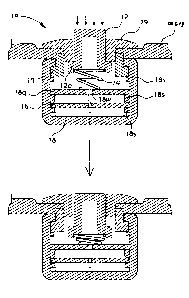
FIG. I illustrates partial sectional views showing the operation of an
active dry sensor module for measurement of bioelectricity in accordance with
the
present invention;
FIG. 2 illustrates plan and side views of a concave active electrode of the
sensor module of the present invention;
FIG. 3 illustrates plan and side views of a toothed active electrode of the
sensor module of the present invention;
FIG. 4 illustrates plan and side views of a spring of the sensor module of
the present invention;
FIG. 5 is a block diagram illustrating the constitution of an amplification
circuit of the sensor module of the present invention;
FIG. 6 illustrates plan and side views of a cap of the sensor module of the
CA 02555761 2006-08-09
WO 2005/065544 PCT/KR2004/001573
6
present invention;
FIG. 7 illustrates plan and side views of a holder of the sensor module of
the present invention;
FIG. 8 is an exemplary view showing the sensor module of the present
invention in an assembled state; and
FIGS. 9A and 9B are perspective and sectional views of a conventional
electrode for measurement of bioelectricity.
[Best Mode]
Now, a preferred embodiment of the present invention will be described in
detail with reference to the accompanying drawings. The accompanying drawings
have been made only for a better understanding of the embodiment of the
present
invention. Thus, the accompanying drawings and the description with reference
to
the drawings do not limit the scope and spirit of the invention.
In the drawings, the same or similar elements are denoted by the same
reference numerals even through they are depicted in different drawings.
An active dry sensor module 10 for measurement of bioelectricity in
accordance with the present invention comprises an active electrode 12, a
spring
14, an amplification circuit 16, a main body 18, and a holder 17 and a cap 19
necessary for fixing the sensor module 10 when the sensor module 10 is
installed
at a headset.
The active electrode 12 is interlocked with the cap 19, and vertically
slides. The upper part of the active electrode 12 is exposed to the outside to
contact a skin, and a latching protrusion 12a, which is latched to the cap 19
inserted into the main body 18, is protruded from the lower part of the active
electrode 12 located in the main body 18. The active electrode 12 is an
essential
element directly contacting the scalp when the active electrode 12 measures a
biomedical signal, for example, EEG. Accordingly, since the reliability of the
measured value of the biomedical signal depends on the active electrode 12,
preferably, the active electrode 12 is plated with gold or silver so that the
conductibility of the active electrode 12 is improved and current easily flows
through the active electrode 12. As shown in FIGS. 2 and 3, preferably, the
surface of the active electrode 12 contacting the scalp of the reagent is
concave or
CA 02555761 2006-08-09
WO 2005/065544 PCT/KR2004/001573
7
toothed so that the contact surface of the active electrode 12 stably contacts
the
scalp of the reagent for a long time. The concave active electrode 12 directly
contacts a bare portion of the scalp, and the toothed active electrode 12'
contacts a
portion having hair of the scalp. Preferably, the concave active electrode 12
is
configured such that a contact surface 12c of the concave active electrode 12
is
similar to the curved surface of the scalp. Further, preferably, the toothed
active
electrode 12' is configured such that a plurality of circular protuberances
12'c are
formed on the contact surface of the toothed active electrode 12', and
contacts the
portion having hair of the scalp.
Hereinafter, although this embodiment will describe the concave active
electrode 12, the toothed active electrode 12' may be used. That is, the shape
and
the material of the active electrode are not limited thereto.
In order to attach the conventional electrode for measurement of
bioelectricity to the scalp, a conductive gel containing a Cl- component is
applied
to the scalp, and then the electrode is attached thereto. However, when the
conductive gel is used, positive (+) ions of metal flowing from the electrode
and
negative (-) ions on the surface of the electrode attract each other, thereby
forming
an electrical double layer, thus generating polarization between the electrode
and
the gel. Accordingly, a half cell potential, which is an undesired potential
difference, is generated between the electrode and a measured portion. The
above half cell potential is several hundreds mV, and more particularly, in
the
case that the electrode is a generally used Ag-AgCI electrode, the half cell
potential is approximately 220W. Generally, the half cell potential is removed
by
common mode voltage of an instrumentation amplifier (IA), which will be later
connected to the electrode, and only a brain wave signal serving as a
differential
component is amplified and is then outputted.
The quality of the brain wave component, passed through the IA, depends
on an electrical resistance component of an interface between the. skin and a
contact surface of an electrolyte. The intensity of the resistance component
reaches several tens of kQ- several hundreds of kQ according to a variable,
such
as the state of the skin, the concentration of the gel used in the electrode,
or the
required time after the gel is applied to the skin. Accordingly, in order to
obtain
low impedance having reliable stability in an initial stage, an electrode gel
containing NaCI having a high concentration of 5-10% is applied to the skin,
such
CA 02555761 2006-08-09
WO 2005/065544 PCT/KR2004/001573
8
as the scalp from which a horny layer is removed. Consequently, this minimizes
a DC offset voltage, generated from a route from the skin to the surface of
the
electrode, and the resistance component, and means that a proper electrode is
selected and the state of the skin, to which the electrode is attached, is
satisfactory.
In the mechanical design of the electrode, the electrode must be designed such
that
an artifact due to a movement between the skin and an electrolyte and a
movement
between the electrolyte and a bonding portion of the electrode is not
generated in
consideration of the shape of the scalp, to which the electrode is attached.
When the above conventional scalp electrode is used, it takes a long time
to prepare the scalp electrode. For example, since the time taken to apply one
conventional electrode to the scalp is 20 seconds to 30 seconds, the time
taken to
measure 64 channels is approximately 30 minutes. In order to shorten the above
time, the electrode may have a cap shape. However, in this case, it also takes
a
considerable time to prepare the electrode. Further, when the conductive gel
is
used, the conductive gel supplies unpleasantness and discomfort to a reagent
except for clinical testing, and damages the scalp in order to perform precise
measurement as described above, thereby causing the danger of viral infection.
Accordingly, in order to solve the. disadvantages of the conventional
electrode for measurement of electricity, the active dry sensor module 10 for
measurement of bioelectricity in accordance with the present invention employs
the active electrode 12 for suppressing the half cell potential and the
generation of
noise without the conductive gel.
A biomedical signal induced from the active electrode 12 is transmitted to
the amplification circuit 16 through the spring 14 plated with the same
material as
that of the active electrode 12.
FIG. 4 illustrates plan and side views of the spring of the sensor module of
the present invention. The spring 14, which is installed in the main body 18,
substitutes for the wire having a considerable length installed in the
conventional
sensor module. Preferably, the spring 14 is a compressed spring, which repels
against the compressive force. Further, preferably, in the same manner as the
active electrode 12, the spring 14 is plated with gold or silver so as to
transmit the
biomedical signal transmitted through the active electrode 12 to the
amplification
circuit 16. One end 14a of the spring 14 mechanically contacts the lower part
of
the active electrode 12 and receives the biomedical signal, and the received
CA 02555761 2006-08-09
WO 2005/065544 PCT/KR2004/001573
9
biomedical signal is transmitted to the amplification circuit 16 connected to
the
other protruded end 14b of the spring 14 by soldering.
The spring 14 of the sensor module 10 of the present invention serves as
pressure supply means for applying the active electrode 12 to the scalp
without the
conductive gel, and serves to damp pressure generated when the active
electrode
12 contacts the scalp. Further, the spring 14 applies pressure of a proper
intensity
to the active electrode 12, thereby preventing the pressure on the interface
between
the scalp and the active electrode 12 from causing reagent's discomfort and a
mark
of the active electrode 12 from remaining on the interface after the
measurement.
FIG. 5 is a block diagram illustrating the constitution of the amplification
circuit of the sensor module of the present invention. As shown in FIG. 5, the
amplification circuit .16 includes an instrumentation amplifier (IA) 16i, a
notch
filter 16n, a band-pass filter 16m, and an amplifier 16r. The protruded end
14b of
the spring 14 is connected to the amplification circuit 16 by soldering so
that the
protruded end 14b is fixed to the lower portion of the inside of the main body
18.
The amplification circuit 16 receives the biomedical signal passed through the
spring 14, and amplifies and filters the biomedical signal so that the
biomedical
signal is easily measured and formed.
The IA, which is conventionally used for measurement of bioelectricity, is
a differential amplifier including a buffer amplifier for eliminating the half
cell
potential and picking out only a pure biomedical signal. The most important
parameter of the IA is a common mode rejection ratio (CMRR). The CMRR is a
parameter indicating how many signals existing by simultaneous input are
removed, and is obtained by dividing a common gain value by a differential
gain
value. The higher the CMRR is, the better characteristics the differential
amplifier indicates. When the conventional Ag/AgCI electrode is used, an
impedance component between the electrode and the scalp is approximately 10-30
W. The IA used for preventing disturbance of an input signal due to the
impedance of the electrode and processing the biomedical signal must have an
input impedance of more than IOOkQ, a CMRR of more than NO, and an overall
gain of approximately 1,000-' 100,000 times.
The active electrode 12 of the sensor module 10 of the present- invention is
a dry electrode, which does not use an electrolyte. Since the input impedance
of
the active electrode 12 is increased maximally to hundreds kQ (200kQ --
300kg),
CA 02555761 2006-08-09
WO 2005/065544 PCT/KR2004/001573
the conventional IA cannot be applied to the active electrode 12. Accordingly,
in
order to reduce the influence of the increased input impedance of the sensor
module 10 and an input noise component thereby, the IA 16i has an input
impedance of 1013kQ, a CMRR of more than 120dB, and band pass characteristics,
5 which has a signal pass band of 0.1-40Hz. The above characteristics cannot
be
exhibited by the conventional IA, but are caused by a specially created
circuit.
That is, the IA includes three amplifiers so that one amplifier serves as a
differential amplifier and the remaining two amplifiers form a feedback loop,
thereby having band pass characteristics as well as an amplification function.
10 Here, the amplification degree of the IA is increased to several ten
thousand times
by varying the value of an internal element, and the amplifier 16r serving as
the
differential amplifier does not amplify a common mode signal for identically
driving two input values, thereby not exhibiting an interference voltage to
the
output.
The noise component is additionally eliminated by the band-pass filter
16m. However, since the noise component of 60Hz is generated from a power
source as well as a human body, the notch filter 16n for additionally
eliminating
the noise component of 60Hz is provided. The notch filter 16n eliminates the
noise component of 60Hz, and filters the biomedical signal processed by the IA
16i one more time, thus adjusting a frequency band. Accordingly, the notch
filter
16n serves as an additional amplifier.
FIG. 6 illustrates plan and side views of a cap of the sensor module of the
present invention, and FIG. 7 illustrates plan and side views of a holder of
the
sensor module of the present invention. An insertion hole 18h, into which the
holder 17 and the cap 19 are inserted, is formed through the upper surface of
the
main body 18, and the active electrode 12, the spring 14, and the
amplification
circuit 16 are located at the inside and outside of the main body 18. The
holder
17 is fixedly inserted into the insertion hole 18h, and screw threads and
screw
hollows, which are engaged with each other, are respectively formed at the
upper
part of the holder 17 and the lower part of the cap 19 so that the cap 19 is
rotated
and fixed to the holder 17. In this case, the holder 17 is integrated with the
main
body 18, and then the integrated assembly of the holder 17 and the main body
18 is
molded.
The cap 19 is used when the sensor module 10 is fixed to a headset.
CA 02555761 2006-08-09
WO 2005/065544 PCT/KR2004/001573
11
When the cap 19 is rotated, the height of the cap 19 is changed so as to
firmly fix
the module 10 to the headset. That is, the sensor module 10 of the present
invention is simply and firmly attached to and detached from the headset by
rotating the cap 19. Preferably, the cross section of the central part of the
cap 19
has a regular ring shape such that an upper protrusion 19u of the cap 19 is
protruded outwardly.
In order to eliminate the signal interference due to the influence of
external environment, preferably, the main body 18 is made of insulating
material,
such as synthetic resin without conductance, and has an external cross section
of a
rectangular shape and an internal cross section of a circular shape so that
the main
body 18 has a hollow structure.
FIG. 8 is an exemplary view showing the sensor module of the present
invention in an assembled state. In order to form the sensor module 10 of the
present invention, the holder 17 and the amplification circuit 16 are
respectively
located at upper and lower portions of a space between left and right body
portions
18a and 18b of the main body 18, and then the left and right body portions 18a
and
18b are connected. The holder 17 and the amplification circuit 16 are latched
onto stoppers 18s symmetrically, formed on the left and right body portions
18a
and 18b of the main body 18, and the movement of the holder 17 and the
amplification circuit 16 is restrained after the. left and right body portions
18a and
18b are connected. The holder 17 is integrated with the main body 18 under the
condition that the upper end of the holder 17 is protruded from the upper
surface of
the main body 18, and is molded together with the main body 18. The holder 17
together with the cap 19 serves to fix the sensor module 10 of the present
invention
to a headset, and to guide the cap 19. The shape of the holder 17 is not
limited.
When the holder 17 is not integrated with the main body 18, the holder may be
latched onto the stoppers 18s of the main body 18 and be fixedly assembled
with
the main body 18. The connection between the holder 17 and the main body 18,
the connection between the amplification circuit 16 and the main body 18, and
the
connection between the holder 17 and the cap 19 are not limited to the
description
of the above embodiment. The above connections are apparent to.those skilled
in
the art, and a detailed description thereof will thus be omitted.
The amplification circuit 16 is connected to the main body 18 by allowing
the lower part of the spring 14 to pass a through hole 18a formed through a
CA 02555761 2006-08-09
WO 2005/065544 PCT/KR2004/001573
12
diaphragm 18q. When the spring 14 is initially molded, a vertical distance
from
one end of the spring 14 to the other end of the spring 14 is properly
obtained.
Thereby, when the spring 14 is compressed by the active electrode 12 inserted
into
the main body 18, the spring 14 has designated elastic energy. As stated in
the
Equation 1 below, when the spring 14 has a large constant, large force must be
applied to the spring 14 for compression. Accordingly, preferably, the spring
14
has a constant determined in the proper range of deviation from 150gf/4.5mm.
[Equation 1]
k=P/a
Here, k represents the constant of the spring 14, P represents load, and a
represents variation.
Thereafter, the spring 14 and the amplification circuit 16 are located in the
main body 18, and the cap 19 is inserted into the holder 17 fixed to the
insertion hole
18h formed through the upper surface of the main body 18 under the condition
that
the active electrode 12 is interlocked with the cap 19. Screw threads and
screw
hollows, which are engaged with those of the holder 17, are formed on the cap
19.
After screw threads and screw hollows formed on the cap 19 and the insertion
hole
18h are engaged with each other, and the cap 19 is rotated to the end, thus
being
fixed. The protruded height of the active electrode 12 is adjusted by rotating
the
cap 19 inserted into the holder 17. Thereby, the active electrode 12
compresses the
spring 14, and the spring 14 has elastic energy and semi-permanently
elastically
moves under the condition that the active electrode 12 is inserted into the
main body
18 by interference fit. One end 14a and the other end 14b of the spring 14
respectively contact the active electrode 12 and the amplification circuit 16
so that
the biomedical signal received from the active electrode 12 is transmitted to
the
amplification circuit 16. The active electrode 12 slides along the inner
surface of
the cap 19, and the sliding of the active electrode 12 is restrained by
latching the
latching protrusion 12a formed on the lower part of the active electrode 12
onto the
lower end of the cap 19. Preferably, the active electrode 12 has a proper
overall
height so that the active electrode 12 is protruded outwardly from the upper
surface
CA 02555761 2006-08-09
WO 2005/065544 PCT/KR2004/001573
13
of the cap 19 by a designated height after -the active electrode 12 is
completely
inserted into the cap 19. Preferably, in order to improve conductance of the
active
electrode 12 and the spring 14, the active electrode 12 and the spring 14 are
plated
with gold or silver.
[Industrial Applicability]
As apparent from the above description, the present invention provides an
active dry sensor module for measurement of bioelectricity, which excludes the
use
of a conductive gel, thereby not supplying unpleasantness and discomfort to a
reagent and preventing the danger of viral infection.
Further, the active dry sensor module of the present invention excludes
the use of a wire for transmission of a biomedical signal, thereby preventing
the
interference of the signal due to a noise component generated from a power
source.
Moreover, the active dry sensor module of the present invention amplifies the
biomedical signal to a designated treatable level, thereby precisely and
easily
measuring the biomedical signal.
Although the preferred embodiment of the present invention has been
disclosed for illustrative purposes, those skilled in the art will appreciate
that
various modifications, additions and substitutions are possible, without
departing
from the scope and spirit of the invention as disclosed in the accompanying
claims.