Language selection

Search

Patent 2556355 Summary

Third-party information liability

Some of the information on this Web page has been provided by external sources. The Government of Canada is not responsible for the accuracy, reliability or currency of the information supplied by external sources. Users wishing to rely upon this information should consult directly with the source of the information. Content provided by external sources is not subject to official languages, privacy and accessibility requirements.

Claims and Abstract availability

Any discrepancies in the text and image of the Claims and Abstract are due to differing posting times. Text of the Claims and Abstract are posted:

  • At the time the application is open to public inspection;
  • At the time of issue of the patent (grant).
(12) Patent: (11) CA 2556355
(54) English Title: CONDUITS
(54) French Title: CONDUITS
Status: Granted
Bibliographic Data
(51) International Patent Classification (IPC):
  • H02G 3/04 (2006.01)
(72) Inventors :
  • RUDDICK, PAUL DAVID (United Kingdom)
(73) Owners :
  • D-LINE (EUROPE) LIMITED (United Kingdom)
(71) Applicants :
  • D-LINE (EUROPE) LIMITED (United Kingdom)
(74) Agent: BERESKIN & PARR LLP/S.E.N.C.R.L.,S.R.L.
(74) Associate agent:
(45) Issued: 2012-08-28
(86) PCT Filing Date: 2005-03-08
(87) Open to Public Inspection: 2005-09-15
Examination requested: 2010-01-14
Availability of licence: N/A
(25) Language of filing: English

Patent Cooperation Treaty (PCT): Yes
(86) PCT Filing Number: PCT/GB2005/000889
(87) International Publication Number: WO2005/086304
(85) National Entry: 2006-08-15

(30) Application Priority Data:
Application No. Country/Territory Date
0405182.7 United Kingdom 2004-03-08

Abstracts

English Abstract


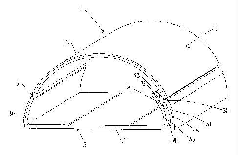
A conduit (1) having a substantially semi-circular outer cross-section
comprising a base portion (3) and a lid portion (2), the lid portion (2) being
attached to the base portion (3) by a hinge (4) and having a clip (23) on the
opposite side, wherein the hinge (4) is located at an angular elevation from
the base of between 10~ and 35~, the base portion (3) having a clip socket for
retaining the clip (23), wherein the clip socket comprises an outer wall (32),
which forms part of the semi-circular outer cross-section, and an inner wall
(33), between which is defined a channel (34) for the clip (23), the height of
the inner wall above the bottom of the base portion (3) being substantially
the same as the height of the hinge (4) above the bottom of the base portion
(3).


French Abstract

Cette invention se rapporte à un conduit (1) ayant une section transversale externe essentiellement semi-circulaire, comprenant une partie base (3) et une partie couvercle (2), laquelle est fixée à la partie base (3) par une charnière (4) et comporte une pince (23) sur le côté opposé. La charnière (4) est situé à une élévation angulaire de la base comprise entre 10· et 35·, la partie base (3) comportant une douille de pince destinée à retenir la pince (23). Cette douille de pince comprend une paroi externe (32), qui fait partie de la section transversale externe semi-circulaire, et une paroi interne (33), entre lesquelles est formé un canal (34) pour la pince (23), la hauteur de la paroi interne au-dessus du fond de la partie base (3) étant essentiellement identique à la hauteur de la charnière (4) au-dessus du fond de la partie base (3).

Claims

Note: Claims are shown in the official language in which they were submitted.


7
CLAIMS

1. A conduit having a substantially semi-circular outer cross-section
comprising a base portion and a lid portion, the lid portion being attached to
the
base portion by a hinge and having a clip on the opposite side, wherein the
hinge
is located at an angular elevation from the base of between 100 and
35°, the
base portion having a clip socket for retaining the clip, wherein the clip
socket
comprises an outer wall, which forms part of the semi-circular outer cross-
section, and an inner wall, between which is defined a channel for the clip,
the
height of the inner wall above the bottom of the base portion being
substantially
the same as the height of the hinge above the bottom of the base portion.

2. A conduit according to claim 1, wherein on a cross-section of the conduit a

line between the hinge and the top of the inner wall is within 100 of parallel
with
the base of the conduit.

3. A conduit according to claim 1, wherein on a cross-section of the conduit a

line between the hinge and the top of the inner wall is within 5° of
parallel with the
base of the conduit.

4. A conduit according to any one of claims 1-3, wherein the hinge is located
at an angular elevation from the base of between 20° and 25°.

5. A conduit according to any one of claims 1-4, wherein the outer wall of the

clip socket is shorter than the inner wall.

6. A conduit according to claim 5, wherein the outer wall has an angular
elevation from the base which is at least 5° less than that of the
inner wall.

7. A conduit according to any one of claims 1-6, wherein the outer wall of the

clip socket has a retaining lip thereon, which engages with a corresponding
retaining groove in the clip.


8
8. A conduit according to claim 7, wherein the portion of the clip which
extends beyond the retaining groove into the channel between the inner and
outer walls of the clip socket extends a short distance beyond the retaining
groove.

9. A conduit according to claim 8, wherein the short distance is an angular
extension of no more than 10° from the centre of the retaining groove
to the end
of the clip.

10. A conduit according to any one of claims 1-9, wherein a sealing gasket is
provided on the clip or the clip socket.

11. A conduit according to any one of claims 1-10, wherein a buffer ledge is
provided in the base portion on the bottom wall and on or adjacent the wall to

which the hinge is attached.

Description

Note: Descriptions are shown in the official language in which they were submitted.


CA 02556355 2006-08-15
WO 2005/086304 PCT/GB2005/000889
1
CONDT51 T S
The present invention relates to conduits for concealing
pipework, wires and the like.
Conduits have been used for many years for concealing pipework
and wires in a domestic and industrial setting. In particular,
surface-mounted conduits are used where it is not desired to
damage the surface along which the wires or pipework is to run,
but the presence of uncovered wires and pipes on the surface
would be unsightly, or possibly dangerous.
Surface-mounted conduits are also useful where the wires or
pipes, and their connectivity are changed periodically, as the
surface-mounted conduit allows for easy access.
The present inventor has previously disclosed in UK Registered
Design Numbers 3010551 and 3010552, surface-mounted conduits
having a semi-circular cross section. These conduits offer
aesthetic advantages over the prior art rectangular cross-
section conduits, but also reduce the problem of dust gathering
in the corners formed with the surface on which they are
mounted. Similar conduits are also described in GB 1 420 216
and US 4 629 826.
The prior art semi-circular cross-section conduits include a
hinged lid to allow access to the channel inside the conduit,
but the location of the hinge immediately adjacent the surface
on which the conduit is mounted causes difficulties in opening
the conduit, as well as in closing the conduit due to the
relationship between the location of the hinge and the location
of the clip.
Accordingly, a first aspect of the present invention provides a
conduit having a substantially semi-circular outer cross-section
comprising a base portion and a lid portion, the lid portion


CA 02556355 2006-08-15
WO 2005/086304 PCT/GB2005/000889
2
being attached to the base portion by a hinge, wherein the hinge
is located at an angular a levation from the base of between 10°
and 35°, and having a clip on the opposite side, the base
portion having a clip socket for retaining the clip, wherein the
clip socket comprises an outer wall, which forms part of the
semi-circular outer cross-section; and an inner wall, between
which is defined a channel for the clip, the height of the inner
wall above the bottom of the base portion being substantially
the same as the height of the hinge above the bottom of the base
portion.
The angular elevation of t he hinge is measured about the centre
of the semi-circle which defines the semi-circular outer cross-
section of the conduit.
l5
The term "substantially semi-circular" as used herein, refers to
a shape which is a semi-circle, or gives the impression of being
semi-circular whilst not requiring exact correspondence with a
semi-circle. The shape may be distorted to some extent, as long
as it retains the appearance of being a semi-circle.
This arrangement contributes to the ease of opening and closing
the conduit lid, whilst maintaining the semi-circular outer
profile of the conduit, and allows for the lid of the conduit to
be folded back when instal ling the conduit, or working inside
the conduit once it is att ached to a surface.
The term "substantially th a same height" means herein that on a
cross-section of the condu it a line between the hinge and the
top of the inner wall is within 10° of parallel with the base of
the conduit. Preferably t he line is within 5° or even 2° of
parallel with the base of the conduit.
It is preferred that the hinge is located at an angular
elevation from the base of between 15° and 30°, and most
preferably between 20° and 25°.


CA 02556355 2006-08-15
WO 2005/086304 PCT/GB2005/000889
3
The outer wall of the clip socket is preferably shorter than the
inner wall. This difference in length can be described as a
difference in angular elevation from the base, with the outer
wall preferably having an angular elevation from the base which
is at least 5°, more preferably 7° or even 10° less, than
that
of the inner wall.
The outer wall of the clip socket preferably has a retaining lip
thereon, which engages with a corresponding retaining groove in
the clip. Thus, the clip is retained in the channel between the
inner and outer walls of the clip socket by the inter-engagement
between the retaining lip of the outer wall and the retaining
groove of the clip.
The portion of the clip which extends beyond the retaining
groove into the channel betwee n the inner and outer walls of the
clip socket may extend the who 1e depth of the channel, i.e. such
that it contacts the base of the channel, but it is preferred
that it only extends a short distance beyond the retaining
groove. This distance may be defined as a angular extension of
no more than 15°, preferably n o more than 10° or even
7°, from
the centre of the retaining groove to the end of the clip.
There may be provided a sealin g gasket on the clip or the clip
socket to enable the conduit t o be water-proof.
A buffer ledge may be provided in the base portion on the bottom
wall and on or adjacent the wall to which the hinge is attached.
This ledge is of such a size t hen when male flush fit
accessories are inserted into the end of the conduit, the semi-
circular outer profile of the conduit is retained by virtue of
'balancing' the presence of th a inner wall of the clip socket.
The conduit is preferably strafi ght, but may have some
flexibility to bend along its length. Preferably lengths of


CA 02556355 2006-08-15
WO 2005/086304 PCT/GB2005/000889
4
conduit are joined by appropriate accessories to accommodate
corners and the like in the surfaces on which it is mounted.
The design of the clip socket and clip as expressed in the above
preferences may also be of benef it in other part-circular cross-
section conduits. Accordingly, a second aspect of the present
invention provides a conduit hav Zng a substantially part-
circular outer cross-section comprising a base portion and a lid
portion, the lid portion being attached to the base portion by a
hinge and having a clip, the base portion having a clip socket
for retaining the clip, wherein the clip socket comprises an
outer wall, which forms part of the part-circular outer cross-
section, and an inner wall, between which is defined a channel
for the clip, wherein the outer wall of the clip socket is
shorter than the inner wall of the clip socket, and the outer
wall of the clip socket has a retaining lip thereon, which
engages with a corresponding retaining groove in the clip, and
wherein the clip extends only a short distance beyond the
retaining groove into the channel between the inner and outer
walls of the clip socket.
The terms used in defining this aspect have the same meaning as
in the previous aspect, and the preferences of the first aspect
also apply to this aspect.
The substantially part-circular cross section is semi-circular
(180°) or less. One particular) y preferred embodiment has a
substantially quarter-circular (90°) cross-section.
Preferred embodiments of the pre sent invention will now be
described with reference to the accompanying figures in which:
Fig. Z shows the cross-section of a conduit according to the
present invention;


CA 02556355 2006-08-15
WO 2005/086304 PCT/GB2005/000889
Fig. 2 shows a perspective view of a short length of the conduit
of Fig. 1;
Fig. 3 shows the cross-section of a conduit accord z ng to the
5 second aspect of the present invention; and
Fig. 4 shows a perspective view of a short length of the conduit
of Fig. 3.
The conduit 1 shown in Figs. 1 and 2 comprises a base portion 3
and a lid portion 2 joined by a hinge 4. The conduit 1 has a
semi-circular outer cross-section.
Opposite the hinge 4 is a clip 23 which is part of the lid 2.
The clip has a retaining groove 22 which interacts with a
retaining lip 36 on an outer wall 32 of a clip socket. The clip
socket also comprises an inner wall 33, and a channel 34 is
defined between the outer wall 32 and the inner wall 34.
The hinge is at an angular elevation of about 22° from the base
35 of the base portion 3, and the inner wall 33 of the clip
socket is at about the same height relative to the base 35. The
elevation of the hinge 4 allows the lid portion 2 t o be folded
almost flat against a surface to which the conduit is attached.
The outer wall 32 of the clip socket is shorter th an the inner
wall 33, and has an angular elevation from the base 35 which is
about 7° less than the inner wall 33. The clip 23 has only a
short extension 24 beyond the retaining groove 22, to allow for
easy disengagement and engagement with the clip so c ket.
The conduit shown in Figs. 1 and. 2 is generally made from PVC,
although the hinge 4 is made from TPE.
The conduit carries a coating 21 and 31 which is a 1so made from
PVC, which allows for different finishes to be given to the
conduit, e.g. wood effect, metal effect.


CA 02556355 2006-08-15
WO 2005/086304 PCT/GB2005/000889
6
The TPE hinge 4 is designed with sufficient tension so that i t
can be held back when the conduit l is open to facilitate the
fixing of cables or pipes. The nature of the hinge 4 also
allows for the lid 2 to be unlocked by being pushed away from
the base portion 3, and acts a cushion to allow the lid 2 to be
gently pushed backwards before it is snap-locked into the cli p
socket.
The inner wall 33 of the clip socket provides sufficient support
for the lid 2 to enable the semi-circular outer profile of th a
conduit l to be maintained.
The conduit 1 shown in Figs. 3 and 4 shares many of the features
of the conduit 1 shown in Figs. l and 2 and these are given t he
same reference numerals.
The conduit 1 has a quarter-circle cross section, and theref~ re
the base portion 3 comprises a base wall 35 and a side wall 3 7,
which are a right-angles to each other.

Representative Drawing
A single figure which represents the drawing illustrating the invention.
Administrative Status

For a clearer understanding of the status of the application/patent presented on this page, the site Disclaimer , as well as the definitions for Patent , Administrative Status , Maintenance Fee  and Payment History  should be consulted.

Administrative Status

Title Date
Forecasted Issue Date 2012-08-28
(86) PCT Filing Date 2005-03-08
(87) PCT Publication Date 2005-09-15
(85) National Entry 2006-08-15
Examination Requested 2010-01-14
(45) Issued 2012-08-28

Abandonment History

There is no abandonment history.

Payment History

Fee Type Anniversary Year Due Date Amount Paid Paid Date
Registration of a document - section 124 $100.00 2006-08-15
Application Fee $400.00 2006-08-15
Maintenance Fee - Application - New Act 2 2007-03-08 $100.00 2006-08-15
Maintenance Fee - Application - New Act 3 2008-03-10 $100.00 2008-03-03
Maintenance Fee - Application - New Act 4 2009-03-09 $100.00 2009-02-27
Request for Examination $800.00 2010-01-14
Maintenance Fee - Application - New Act 5 2010-03-08 $200.00 2010-02-05
Maintenance Fee - Application - New Act 6 2011-03-08 $200.00 2011-02-28
Maintenance Fee - Application - New Act 7 2012-03-08 $200.00 2012-02-29
Final Fee $300.00 2012-06-05
Maintenance Fee - Patent - New Act 8 2013-03-08 $200.00 2013-02-21
Maintenance Fee - Patent - New Act 9 2014-03-10 $200.00 2014-02-19
Maintenance Fee - Patent - New Act 10 2015-03-09 $250.00 2015-02-19
Maintenance Fee - Patent - New Act 11 2016-03-08 $250.00 2015-12-03
Maintenance Fee - Patent - New Act 12 2017-03-08 $250.00 2016-11-22
Maintenance Fee - Patent - New Act 13 2018-03-08 $250.00 2017-10-30
Maintenance Fee - Patent - New Act 14 2019-03-08 $250.00 2019-01-07
Maintenance Fee - Patent - New Act 15 2020-03-09 $450.00 2019-12-18
Maintenance Fee - Patent - New Act 16 2021-03-08 $459.00 2021-03-08
Maintenance Fee - Patent - New Act 17 2022-03-08 $458.08 2022-02-15
Maintenance Fee - Patent - New Act 18 2023-03-08 $473.65 2023-02-16
Maintenance Fee - Patent - New Act 19 2024-03-08 $624.00 2024-02-16
Owners on Record

Note: Records showing the ownership history in alphabetical order.

Current Owners on Record
D-LINE (EUROPE) LIMITED
Past Owners on Record
RUDDICK, PAUL DAVID
Past Owners that do not appear in the "Owners on Record" listing will appear in other documentation within the application.
Documents

To view selected files, please enter reCAPTCHA code :


To view images, click a link in the Document Description column. To download the documents, select one or more checkboxes in the first column and then click the "Download Selected in PDF format (Zip Archive)" or the "Download Selected as Single PDF" button.

List of published and non-published patent-specific documents on the CPD .

If you have any difficulty accessing content, you can call the Client Service Centre at 1-866-997-1936 or send them an e-mail at CIPO Client Service Centre.


Document
Description 
Date
(yyyy-mm-dd) 
Number of pages   Size of Image (KB) 
Drawings 2006-08-15 2 41
Claims 2006-08-15 2 54
Abstract 2006-08-15 1 61
Representative Drawing 2006-08-15 1 13
Description 2006-08-15 6 220
Cover Page 2006-10-12 2 44
Claims 2011-08-29 2 62
Representative Drawing 2012-08-01 1 13
Cover Page 2012-08-01 1 44
PCT 2006-08-15 2 68
Assignment 2006-08-15 12 284
PCT 2006-08-15 1 45
Prosecution-Amendment 2006-11-06 1 24
PCT 2006-08-16 6 226
Prosecution-Amendment 2010-01-14 1 41
Prosecution-Amendment 2011-08-29 6 199
Prosecution-Amendment 2011-04-11 2 40
Correspondence 2012-06-05 1 42