Note: Descriptions are shown in the official language in which they were submitted.
CA 02556996 2006-08-21
WO 2005/085904 PCT/GB2005/000843
Movement Control System
This invention relates to movement control aids for vehicles or robotic
systems,
especially to automated control systems such as automated parking systems for
vehicles, docking control and object manipulation systems.
There is an ongoing desire to provide and improve movement control systems in
a wide
range of applications from improving proximity sensors for vehicles, to
automated control
systems for vehicles or control of robotic systems.
Thus according to the present invention there is provided a movement control
system
comprising at least one three-dimensional imaging system adapted to image an
environment and a processor for analysing the image so at to create a model of
the
environment and generate a movement control signal based on the created model
wherein the three-dimensional imaging system comprises an illumination means
for
illuminating a scene with a projected two dimensional array of light spots, a
detector for
detecting the location of spots in the scene and a spot processor adapted to
determine,
from the detected location of a spot in the scene, the range to that spot.
Thus the present invention relates to a movement control system comprising at
least one
three dimensional imaging system adapted to image an environment and a
processor for
analysing the image so at to create a model of the environment and generate a
movement control signal based on the created model.
The three-dimensional imaging apparatus is one which acquires range
information to the
plurality of spots projected onto the scene, in effect a two dimensional array
of range
values. This three dimensional image can be acquired with, or without,
intensity
information from the scene, i.e. a usual image as might be taken by a camera
system.
The three-dimensional imaging system acquires one or more three dimensional
images
of the environment and uses these images to create a model of the environment
from
which a movement control signal can be generated. As the three dimensional
imaging
system projects an array of spots it is good at determining range to surfaces,
even
generally featureless surfaces.
Conveniently the at least one three-dimensional imaging apparatus is adapted
to acquire
three dimensional images of the environment at a plurality of different
positions and the
CA 02556996 2006-08-21
WO 2005/085904 PCT/GB2005/000843
2
processor is adapted to process images from the different positions so as to
create the
model of the environment.
Recording three-dimensional images of the environment at a plurality of
positions
effectively scans the environment to provide more information. This can remove
the
effects of shadowing, where a part of the foreground obscures the background
from a
particular viewpoint. Also where the environment in question is relatively
large a single
view may not provide accurate enough information.
Preferably the processor is also adapted to apply stereo image processing
techniques to
images from different positions in creating the model of the environment.
Stereo image
processing techniques are known in the art and rely on two different
viewpoints of the
same scene. The parallax between identified objects in the scene can give
information
about the relationship of objects in the scene. Stereo processing techniques
are very
useful for identifying the edges of objects in the scene as the edges are
clear features
that can be identified from the parallax between images. Stereo imaging
however
generally provides little information about any variations in range of a
continuous surface.
By contrast spot projection based three dimensional imaging systems determine
the
range to each detected spot and so give tots of information about surfaces but
can only
identify the presence of a range discontinuity, i.e. edge, between two
detected spots and
not its exact location. An exact edge location may be needed if manipulation
of an object
is intended. Thus the stereo imaging can be used to identify the edges and
corners of
objects in the scene and the range information from the three dimensional
imaging
system can be used to fill out the contours of the surfaces of any objects.
Thus using
three-dimensional imaging together with stereo imaging techniques lots of
information
regarding the location of objects in an environment can be generated and used
to form a
model of the environment
As mentioned stereo image processing techniques can be very useful and can be
achieved with a single imager using frame to frame stereo imaging, for
instance the
separation between viewpoints being provided by motion of the platform on
which the
movement control system is mounted or by a deliberated scan of the three
imaging
system. For a road vehicle the direction of movement is horizontal and it may
be
advantageous to have stereo imaging in the vertical direction too, for
instance to resolve
kerbs etc.
CA 02556996 2006-08-21
WO 2005/085904 PCT/GB2005/000843
3
However the advantage of at feast two viewpoints is such that preferably the
system
comprises at least two imaging apparatuses arranged to look toward the same
part of the
environment from different viewpoints. Thus even without motion of the three
dimensional imager relative to the scene, for instance as would be the case
when a
vehicle is first started and there is.no motion history available, the
different imaging
apparatuses have different viewpoints and stereo data is also available. Of
course
motion of the'imaging system relative to the scene may generate other frame to
frame
stereo views that can be used in generating the model of the scene. There may
be three
imaging apparatuses arranged to look towards the same part of the environment
from
different viewpoints not on the same axis. Conveniently the axis of separation
of at least
two of the imaging apparatuses may be' different, say substantially
orthogonal, to the
usual direction of motion of a vehicle on which they are mounted.
The movement control signal generated will depend upon the application to
which the
present invention is applied and could be simply an information or warning
signal to an
operator or could allow direct control of a moveable object.
For instance the movement control system could be implemented on a vehicle to
provide
safety or warning information. For instance a three dimensional imaging system
could
be located at or near the extremity of a vehicle and could provide information
about how
close the vehicle is to other objects. A road vehicle such as a car could have
a three
dimensional imaging sensor constantly determining the range to other vehicles
and
stationary objects to provide a warning should another vehicle come too close
or even
provide some safety action such as applying the brakes or even steering the
vehicle.
Preferably the vehicle would be provided with a plurality of three-dimensional
imaging
systems, each imaging system arranged to image the environment in the vicinity
of an
extremity of the vehicle and/or any blind spots of the vehicle, e.g. a car
could have an
imaging system provided in the vicinity of each corner, for instance embedded
into the
light clusters. Each imaging system could have its own processor or they could
share a
common processor. Alternatively or additionally the movement control system
could be
activated in certain situations such as parking. The information from the
model of the
environment, such as the parking space or garage, could be used to give
indications of
how close the vehicle is to another object. The indications could be audible
or visible or
both. The system could also be mounted on an aircraft to monitor the
extremities of the
aircraft, for instance the wingtips in a fixed wing aircraft. Aircraft
manoeuvring on the
ground need to be careful not to collide with objects at an airport Again the
control signal
CA 02556996 2006-08-21
WO 2005/085904 PCT/GB2005/000843
4
could be a warning signal to the flight crew andlor ground crew or the control
system
could take preventative measures to avoid collision. The system could equally
be
utilised to optimise docking procedures such as for aircraft passenger
walkways, in-flight
refuelling, space platforms etc. or for robotic arm control systems which
control how the
arm manipulates objects in the environment, e.g. for grasping or stacking
objects.
The movement control system could also provide some degree of automated
control of
the vehicle. Vehicles could be provided with self navigation systems, for
instance robotic
systems having self navigation. Vehicles could be provided with self
positioning systems
- the images from the three dimensional imager or imagers being used to create
a model
of the environment with the control signal directing a series of controlled
movements of
the vehicle to position the vehicle accordingly. For instance a car could be
provided with
a parking system to allow parking of the car or a fork lift truck or similar
may be
automated and the movement control system could allow the fork lift truck to
accurately
position itself in relation to an object to be picked up or in relation to a
space in which to
deposit a carried item.
The movement control system could also be implemented on a moving object which
is
not a vehicle, such as a robotic arm. Robotic arms are often used on
production lines
where objects are found in a predetermined location relative to the arm.
However to
account for variations in object location or to allow very accurate
interfacing between the
arm and the object it may be necessary to adjust the arm position in each
case. Indeed
allowing the arm controller to form a model of an environment in a automated
flow
through process may allow automation of task presently unsuitable for
automation, e.g.
sorting of waste perhaps for recycling purposes. Moveable arms are also
provided on
other platforms for remote manipulation of objects, e.g. bomb disposal or
working in
remote or hazardous environments. To provide for multiple viewpoints to
generate full
data about the environment the robotic arm, or at least part thereof, could be
moved to
scan the three dimensional imaging system with regard to the environment.
Preferably the system also includes a means of determining the relative
location of the
three-dimensional imaging apparatus when a range image is acquired and the
processor
uses the information about relative location in creating the model. In order
to create the
model from the various images the processor needs to know how all the images
relate to
the environment. Generally this involves knowing where the imaging system was
for a
particular acquired image relative to the other images. The movement control
system
CA 02556996 2006-08-21
WO 2005/085904 PCT/GB2005/000843
could be adapted to acquire images only at certain relative positions - for
instance a
robotic arm may be provided with a movement control system according to the
present
invention and the arm may be adapted to move to certain predetermined
positions to
acquire the images. Thus the relative position of the imaging system is
predetermined.
5 In other applications however the relative positions at which images are
acquired will not
be predetermined and so it will be necessary to monitor the relative location
or acquire
information about the relative positions of the images by identifying common
reference
features in the scene.
The relative location could be achieved by providing the movement control
system with a
location monitor. For instance a GPS receiver could be included or location
sensors that
determine location relative to a fixed point such as a marker beacon etc. The
location
sensors could include compasses, magnetic field sensors, accelerometers etc.
The
skilled person would be aware of a variety of ways of determining the location
of the
imaging system for each image.
Alternatively the relative location could be determined by monitoring travel
of the platform
on which the movement control system is mounted. On a vehicle such as a car
the
motion of the wheels is already monitored for speed/distance information. This
could be
coupled into a simple inertial sensor to provide relative location
information. Indeed if the
movement control apparatus is only used in situations where the vehicle is
travelling in a
straight line the distance travelled alone will be sufficient to determine the
relative motion.
For-some applications this will be sufficient - for example the system could
be used as a
parking system. The driver could activate the movement control system and
drive past
the parking space. The three dimensional imaging apparatus would capture a
number of
images of the space as the vehicle passed by and generate a model of the
space. The
movement control signal could then comprise a set of instructions on how to
best
manoeuvre into the space. These instructions could be relayed to the driver by
some
means, e.g. visual or aural aids, or the parking could be automated and the
movement
control signal could be used by an automatic drive unit to position the
vehicle. Such a
system could find application on a wide range of vehicles, e.g. it would be
employed to
park aircraft or position lifting vehicles such as fork-lift trucks.
In another aspect of the invention there is therefore provided a vehicle
positioning
system comprising a three dimensional imaging apparatus arranged to acquire a
plurality
of three dimensional images of a target area as the vehicle moves in respect
to the target
CA 02556996 2006-08-21
WO 2005/085904 PCT/GB2005/000843
6
area and a processor adapted to process the images from the different
positions so as to
create the model of the environment and determine how to position the vehicle
with
respect to the target area.
The target area may be a parking space and the vehicle may pass the parking
area to
acquire the images in which case the processor determines how to park the
vehicle in
the parking area. Thus a driver wanting to park a vehicle may activate the
parking
system and drive past the space in which it is wished to park. The three-
dimensional
imaging apparatus takes a series of images of the parking space and the
processor
builds a model of the space and the position of the vehicle and determines how
best to
park to vehicle. The system may comprise a user interface which could be used
to relay
parking instructions. For instance the interface could be a computer generated
speech
unit giving instructions on when to reverse, when and how to steer, when to
step etc.
Additionally or alternatively a visual display could be used to display the
vehicles location
relative to the space and objects and give parking instructions.
The system could comprise a drive unit for automatically moving the vehicle
and the
processor could control the drive unit to move the vehicle into the space.
Before moving
the interface could present a display of proposed movement or some parking
options so
that the driver is confident that the vehicle is going to park correctly.
In either case, whether the driver is guided by the processor via the
interface or vehicle
parks automatically the model of the environment is constantly updated. This
is
necessary in case a pedestrian steps into the parking area or a parked vehicle
starts to
move but in addition the constant monitoring also allows the model to be
refined and the
parking instructions updated as necessary. Where the driver is actually
controlling the
vehicle in parking and receiving instructions from the parking aid the model
needs
updating to take account of what the driver actually does as it will rarely be
exactly what
was suggested.
Alternatively the vehicle could be an object moving device such as a fork lift
truck and the
target area could either be a location to pick up on object or an area where
it is wished to
stack or deposit an object. In which case the vehicle could pass be the area
to
determine how best to left or deposit the item and then act accordingly, again
either via
instructions to an operator or automatically.
CA 02556996 2006-08-21
WO 2005/085904 PCT/GB2005/000843
7
It should be noted that any type of vehicle could be equipped with the control
system
according to the present invention. For instance aircraft moving around an
airport need
to be parked at the correct gate position on landing or moved into hangars for
storage or
maintenance. Lorries could benefit for a parking control system to allow
accurate
alignment to loading bays.
The present invention also relates to a method of generating instructions for
positioning a
vehicle comprising the steps of moving the vehicle past a target area and
recording
three-dimensional images of the target area from a plurality of different
positions,
processing the three-dimensional images to create a model of the target area
relative to
the vehicle and based on the model calculating how to position the vehicle as
required
with respect to the target area. The method preferably involves using stereo
imaging
technique on the three-dimensional images acquired from different viewpoints
in creating
the model. The method may comprise the additional step of relaying
instructions to a
vehicle operator via an interface or may include the step of operating a drive
unit to
automatically position the vehicle. The vehicle may be a car and the method
may be a
method of generating a set of parking instructions.
As mentioned the invention is not just applicable to parking and can aid
general driving.
In another aspect then there is provided a vehicle driving aid comprising a
movement
control system as described above wherein at least one 3D imager is adapted to
image a
vehicle blind spot and the movement control signal is a warning that an object
has
entered the vehicle blind spot. The vehicle blind spot could be any part of
the
environment around a vehicle which the driver can not see or see easily, for
instance
areas not revealed by looking in wing mirrors or areas which are obscured by
part of the
vehicle.
In general the invention is applicable to any moving object which needs to be
accurately
or safely positioned with respect to an object or gap. As mentioned robotic
arms on
production lines that show some variability may need to accurately interface
with objects
on the line. Remote vehicles or those operating in hazardous environments may
also
need to interface with objects, e.g. underwater vessels or space vehicles or
robotic
vehicles such as used in explosive ordinance disposal..
Thus in another aspect there is provided a docking control system for a
moveable
platForm comprising a three-dimensional imaging apparatus arranged acquire
three
CA 02556996 2006-08-21
WO 2005/085904 PCT/GB2005/000843
8
dimensional images of an environment from a plurality of different positions
and a
processor adapted to process the images from the different positions so as to
create the
model of the environment in relation to the moveable platform and provide a
control
signal to a drive means of the moveable platform so as to dock the moveable
platform
with the environment.
As used herein the term dock should be read broadly to mean to position the
moveable
platform in accurate location with a desired part of the environment, e.g. to
grasp an
object with a robotic arm, locate a fork-lift to engage with a pallet,
position a vehicle in a
garage etc. The moveable platform could be any moveable object such as a
vehicle or
moveable arm. The present invention also therefore relates to a robotic arm
control unit
comprising a three-dimensional imaging apparatus arranged acquire three
dimensional
images of an environment from a plurality of different positions and a
processor adapted
to process the images from the different positions so as to create the model
of the
environment in relation to the moveable platform and provide a control signal
to a drive
means of the robotic arm to either engage an object or accurately place an
object. This
aspect of the invention therefore provides control for a 'pick and place'
robotic arm which
is capable of engaging with objects, for instance to lift in a safe manner and
accurately
place them, for instance positioning objects in a substrate. The present
invention allows
for variations in position of an object or substrate from one piece to another
on an
assembly line and ensures that the arm picks up the object in the right way
and
accurately positions the object with respect to the substrate - thus avoiding
accidental
damage and giving better alignment.
Developing a full three dimensional model of the environment may not be
required at all
times or for all operations. For instance imagine an automated vehicle for
moving object
between locations, say an automated fork lift truck. When moving between
locations,
say a particular location in a warehouse and a loading bay, the vehicle may
move
according to predetermined instructions and movement control is provided by
position
monitoring means, e.g. laser guidance, onboard GPS etc. When the vehicle is
moving
between locations a full model of the environment may not be required.
Nevertheless a
proximity sensor of some sort may be needed as a collision avoidance system to
detect
people or debris in the path of vehicle. Once the vehicle has reached the
location in the
warehouse where it is needed to pick up or stack/deposit an object then full
information
about the target area may be required so that the object can be picked up or
stacked
correctly. Therefore in another aspect of the invention there is provided a
movement
CA 02556996 2006-08-21
WO 2005/085904 PCT/GB2005/000843
9
control means for a vehicle operable in two modes, a movement mode in which a
proximity sensor operates to detect any objects within the path of the
vehicle, and an
interaction mode in which a three dimensional ranging means determines range
information about a target area to form a model of the target area.
Therefore in movement mode the movement control means effectively monitors the
path
the vehicle is moving on for a short distance ahead to ensure that the vehicle
does not
collide with a person or an obstacle on that path. Using a simple proximity
sensor means
that processing is very fast and simple - is something in the way or not. The
range in
which to detect obstacles will in part by determined by the vehicle speed and
the need to
prevent collision but for an automatic fork lift truck or the like may be a
few tens of
centimetres.
Once the vehicle arrives at its destination, the target area, it switches to
interaction
mode. Here a three dimensional range means acquires range information about
the
target area in order to form a model of the target area. Preferably the
ranging means is a
three dimensional imaging means as described above with respect to other
aspects of
the invention. Once a model of the area has been acquired the movement control
means may then control the vehicle to perform a predetermined task, such as
acquiring
the uppermost box in a stack or deposit an object onto a stack. In order to
form a good
model of the target area the three dimensional imaging means in interaction
mode may
acquire more than one viewpoint of the target area. All of the embodiments and
advantages of the other aspects of the invention may be applied to this aspect
of the
invention when in interactive mode
When in movement mode if an obstacle is detected various strategies to
navigate the
obstacle could be employed. For instance the vehicle could halt and wait to
see if the
obstacle moves - for instance a person or other vehicle moves out of the way -
or it
could have a set movement pattern, e.g. to the side, to determine whether
there is a
navigable path past a static obstacle. It could also use an alternative route
to its
destination if available. Alternatively the movement control system could
switch to
interactive mode to navigate the obstacle.
The proximity sensor may be any type of proximity sensor which is fast enough
for the
expected vehicle speeds and has good enough range and area coverage. More than
one proximity sensor ma.y be used at different parts of the vehicle.
CA 02556996 2006-08-21
WO 2005/085904 PCT/GB2005/000843
In one embodiment however the three dimensional imaging means is also used as
a
proximity sensor. However rather than process all range information to
determine a full
range profile the three dimensional range system could be operated in a
proximity sensor
5 mode to simplify, and therefore speed, processing.
PCT patent application publication WO 2004/044619 describes a proximity sensor
based
on a three dimensional spot projection system such as described previously. In
such a
proximity sensor a projector array projects an array of spots and a detector
detects any
10 spots in the scene. Between the detector and the scene is a mask having at
least one
aperture so that the detector only sees part of the scene. A spot will only be
visible to
the detector if it appears in part of the scene which can be seen through the
mask and
the arrangement is such that this corresponds to a certain range band.
Therefore
detection of a spot means that an object is within a certain range band and
absence of a
spot means there is nothing within that range band. Thus the detection or
otherwise of a
spot can be a very simple indication of the presence or otherwise of an object
within a
certain range band. For instance the three dimensional imaging system could be
mounted on top of the vehicle and directed to look at the area in front of the
vehicle and
the visible range band could correspond to the expected floor level in front
of the vehicle.
In such an arrangement were the floor in front of the vehicle level and
unobstructed the
detector would see spots through the apertures. Were however there to be a
hole in the
floor or an object on the floor (or indeed anywhere within the line of
projection of the spot
projector) then the range to the reflected spot would change and so the spot
would move
to a part of the scene which is masked. The disappearance of a spot would then
be
indicative of an obstacle. An additional three dimensional imaging system
could be
arranged at floor level looking along the direction of motion and could be
arranged so
that for a clear path no spots are detected but a spot appearing in an
unmasked part of
the detector array is indicative of an object within a certain range in front.
The simple detection of the appearance or disappearance of a spot can be
determined
rapidly using minimal processing power.
The present invention could therefore use a three dimensional imaging system
which can
removably introduce a mask into the optical path to the detector. For instance
a spatial
light modulator such as an LCD could be switched to and from a transmissive
state in
interactive mode, where full processing of all spots is required, and a state
where a mask
CA 02556996 2006-08-21
WO 2005/085904 PCT/GB2005/000843
11
pattern in displayed in movement mode. Alternatively there may be no physical
mask
and the mask effectively applied by processing the detector output. For
instance a
bitmap pattern corresponding to the mask could be applied to the detector
outputs to
remove any output from a notionally masked part of the detector array. This
would be an
easy processing step and would result in an output corresponding only to the
notionally
unmasked portions of the display which again could be monitored simply for a
chance in
intensity etc.
The three=dimensional imaging system used in any of the above aspects of the
invention
preferably needs to provide accurate range information to a high resolution in
the scene
in real time. Ideally the three-dimensional imaging system is compact and is
relatively
inexpensive.
As mentioned previously the illumination means illuminates the scene with an
array of
spots. The detector then looks at the scene and the spot processor, which may
or may
not be the same processor that creates the model of the environment,
determines the
location of spots in the detected scene. The apparent location of any spot in
the array
will change with range due to parallax. As the relationship of the detector to
the
illumination means is known, the location in the scene of any known spot in
the array can
yield the range to that point.
Of course, to be able to work out the range to a spot, it is necessary to know
Which spot
in the array is being considered. Prior art ranging system using structured
illumination
have previous used single spot systems - where there is only one spot in the
scene and
so there is no difficulty. Some systems have used linear beams but even when
using a
linear beam the beam is projected so as to be parallel to one direction, say
the y-
direction. For each value in the y-direction then the actual x-position in the
scene can
then be used to determine the range.
Were a two dimensional array of spots to be used however the spots would be
distributed in both the x and y directions. The skilled person would therefore
not be
inclined to use a two dimensional array of spots as they would have thought
that this
would have meant that the ranging system would either be unable to determine
which
spot was which and hence could not perform ranging or would produce a result
that
could suffer from errors if the wrong spot had been considered. Some prior art
system
have projected a fi~o dimensional array of spots but only in instances with a
narrow
CA 02556996 2006-08-21
WO 2005/085904 PCT/GB2005/000843
12
operating range, where no ambiguity is likely to result, or with known types
of continuous
objects. The imaging system used in the present invention allows use of a two
dimensional array of spots for simultaneous ranging of a two-dimensional scene
of
unknown objects over a wide operating range and uses various techniques to
avoid
ambiguity over spot determination. Preferably the three dimensional imaging
system
used is that described in PCT patent application publication WO 2004/044525.
As used herein the term array of spots is taken to mean any array which is
projected
onto the scene and which has distinct areas of intensity. Generally a spot is
any distinct
area of high intensity radiation and may, as will be described later, be
adapted to have a
particular shape. The areas of high intensity could be linked however provided
that the
distinct spot can be identified. For instance the illumination means may be
adapted to
project an array of intersecting lines onto the scene. The intersection of the
lines is a
distinct point which can be identified and is taken to be a spot for the
purposes of this
specification.
Conveniently the illumination means and detector are arranged such that each
spot in
the projected array appears to move in the detected scene, from one range to
another, ,
along an axis and the axis of apparent motion of each adjacent spot in the
projected
array is different. As will be explained later each spot in the array will
appear at a
different point in scene depending upon the range to the target. If one were
to imagine a
flat target slowly moving away from the detector each spot would appear to
move across
the scene. This movement would, in a well adjusted system used in certain
applications,
be in a direction parallel to the axis joining the detector and illumination
means,
assuming no mirrors etc. were placed in the optical path of the detector or
illumination
means. Each spot would however keep the same location in the scene in the
direction
perpendicular to this axis. For a different arrangement of illumination means
and
detector the movement would appear to be along generally converging lines.
Each projected spot could therefore be said to have a locus corresponding to
possible
positions in the scene at different ranges within the operating range of the
system, i.e.
the locus of apparent movement would be that part of the axis of apparent
motion at
which a spot could appear, as defined by the set-up of the apparatus. The
actual
position of the spot in the detected scene yields the range information. Where
the
apparent direction of movement of a spot at various ranges happens to be the
same as
for another spot then the loci corresponding to the different spots in the
projected array
CA 02556996 2006-08-21
WO 2005/085904 PCT/GB2005/000843
13~
may overlap. In which case the processor would not be able to determine which
spot in
the projected array is being considered. Were the loci of spots which are
adjacent in the
projected array to overlap, measurement of the location in the scene of a
particular spot
could correspond to any of a number of different ranges with only small
distances
between the possible ranges. For example, imagine the array of spots was a two
dimensional array of spots in an x-y square grid formation and the detector
and
illumination means were spaced apart along the x-axis only. Using Cartesian co-
ordinates to identify the spots in the projected array with (0,0) being the
centre spot and
(1,0) being one spot along the x-axis, the location in the scene of the spot
at position
(0,0) in the projected array at one range might be the same as the position of
projected
spot (1, 0) at another slightly different range or even projected spot (2,0)
at a slightly
different range again. The ambiguity in the scene would therefore make range
determination difficult.
Were however the detector and illumination means arranged such that the axis
between
them was not parallel to either the x-axis or the y-axis of the projected
array then
adjacent spots would not overlap. Ideally the locus of each spot in the
projected array
would not overlap with the locus of any other spot but in practice with
relatively large
spots and large arrays this may not be possible. However, if the arrangement
was such
that the loci of each spot only overlapped with that of a spot relatively far
removed in the
array, then although ambiguity would still be present the amount of ambiguity
would be
reduced. Further the difference in range between the possible solutions would
be quite
large. For example the range determined were a particular projected spot,
(0,4) say, to
be detected at one position in the scene could be significantly different from
that
determined if a spot removed in the array (5,0) appeared at the same position
in the
scene. In some applications the operating range may be such that the loci
corresponding to the various possible locations in the scene of the spots
within the
operating window would not overlap and there would be no ambiguity. Even where
the
range of operation would allow the loci of spots to overlap the significant
difference in
range could allow a coarse estimation of range to be performed to allow unique
determination of which spot was which with the location of each spot in the
scene then
being used to give fine range information.
One convenient way of determining coarse range information involves the
illumination
means and detector being adapted such that a projected array of spots would
appear
sharply focussed at a first distance and unfocussed at a second distance, the
first and
CA 02556996 2006-08-21
WO 2005/085904 PCT/GB2005/000843
14
second distances being within the operating range of the apparatus. The spot
processor
is adapted to determine whether a spot is focussed or not so as to determine
coarse
range information. For example if a detected spot could correspond to
projected spot
(0,4) hitting a target at close range or projected spot (5,0) hitting a target
at long range
the spot processor could look at the image of the spot to determine whether
the spot is
focussed or not. If the illumination means and detector were together adapted
such that
the spots were focussed at long range the determination that the spot in
question was
focussed would mean that the detected spot would have to be projected spot
(5,0) hitting
a target at long range. Had an unfocussed spot been detected this would have
corresponded to spot (0,4) reflected from a target at close range. Preferably
in order to
ease identification of whether a spot is focussed or not the illumination
means is adapted
to project an array of spots which are non-circular in shape when focussed,
for instance
square. An in focus spot would then be square whereas an unfocussed spot would
be
circular. Of course other coarse ranging methods could be used - the size of a
spot
could be used as an indication of coarse range.
As an additional or alternative method of resolving possible ambiguity the
illumination
means could be adapted to periodically alter the two dimensional array of
projected
spots, i.e. certain spots could be turned on or off at different times. The
apparatus could
be adapted to illuminate the scene cyclically with different arrays of spots.
In effect one
frame could be divided into a series of sub-frames with a sub-array being
projected in
each sub-frame. Each sub-array would be adapted so as to present little or no
range
ambiguity in that sub-frame. Over the whole frame the whole scene could be
imaged in
detail but without ambiguity.
An alternative approach could be to illuminate the scene with the whole array
of spots
and identify any areas of ambiguity. If a particular detected spot could
correspond to
more than one projected spot at different ranges, one or more.of the possible
projected
spots could then be deactivated so as to resolve the ambiguity. This approach
may
require more processing but could allow quicker ranging and would require a
minimum of
additional sub-frames to be acquired to perform ranging.
Additionally or alternatively the illumination means may be adapted so as to
produce an
array of spots wherein at least some projected spots have a different
characteristic to
their adjacent spots. The different characteristic could be colour or shape or
both.
Having a different colour or shape of spot again reduces ambiguity in detected
spots.
CA 02556996 2006-08-21
WO 2005/085904 PCT/GB2005/000843
Although the loci of different spots may overlap, and there may be some
ambiguity purely
based on spot location in the scene, if the projected spots giving rise to
those loci are
different in colour and/or shape the spot processor would be able to determine
which
spot was which and there would be no ambiguity. The detector and illumination
means
5 are therefore preferably arranged such that if the locus of one projected
spot does
overlap with the locus of one or more other projected spots at least the
nearest projected
spots having a locus in common have different characteristics.
As mentioned above a preferred embodiment of the present invention images the
scene
10 from more than one viewpoint and may use the data from the multiple
viewpoints in
determining range. For instance there may be ambiguity in the actual range to
a spot
detected in the scene from a first viewpoint. The particular spot could
correspond to a
first projected spot in the array reflected from a target at a first range or
a second
(different) projected spot in the array reflected of a target at a second
(different) range.
15 These possibilities could then be tested by looking at the data from the
other viewpoint.
If a particular spot as detected from the other viewpoint would correspond to
the second
projected spot reflected from the target at the second range but there is no
spot detected
from the second viewpoint which corresponds to the first projected spot in the
array
reflected from a target at the first range then the ambiguity is removed and
the particular
spot identified - along with the range thereto. Additionally or alternatively
range
information from stereo processing techniques could be used in spot
identification.
As mentioned above the spots may comprise intersections between continuous
lines.
The detector can then locate the spots, or areas where the lines intersect, as
described
above. Preferably the illumination means projects two sets of regularly spaced
lines, the
two sets of lines being substantially orthogonal.
Using intersecting lines in this manner allows the detector to locate the
position of the
intersection points in the same manner as described above. Once the
intersection points
have been found and identified the connecting lines can also be used for range
measurements. In effect the intersection points are used to identify the
various lines in
the projected array and once so identified all of the points on that line can
be used to
give range information. Thus the resolution of the range finding apparatus can
be
improved over that using only separated spots.
CA 02556996 2006-08-21
WO 2005/085904 PCT/GB2005/000843
16
The detector is conveniently a two dimensional CCD array, i.e. a CCD camera. A
CCD
camera is a relatively cheap and reliable component and has good resolution
for spot
determination. Other suitable detectors would be apparent to the skilled
person however
and would include CMOS cameras.
Conveniently the illumination means is adapted such that the two dimensional
array of
spots are infrared spots. Using infrared radiation means that the spots do not
affect the
scene in the visible range. The detector may be adapted to capture a visible
image of
the scene as well as the location of the infrared spots in the scene. However
the
wavelength of the illumination means can be tailored to any particular
application. For
instance for use underwater a wavelength that is not strongly absorbed in
water is used,
such as blue light.
The length of the baseline between the detector and the illumination means
determines
the accuracy of the system. The term baseline refers to the separation of the
line of sight
of the detector and the line of sight of the illumination means as will be
understood by
one skilled in the art. As the skilled person will understand the degree of
apparent
movement of ariy particular spot in the scene between two different ranges
will go up as
the separation or baseline between the detector and the illumination means is
increased.
An increased apparent movement in the scene between different ranges obviously
means that the difference in range can be determined more accurately. However
equally
an increased baseline also means that the operating range in which there is no
ambiguity
is also reduced.
The baseline between the detector and the illumination means is therefore
chosen
according to the particular application. For a ranging apparatus intended to
work over an
operating distance of say 0.5m to 2.Om, the baseline of the detector and the
illumination
means is typically approximately 60mm.
It should be noted that whilst the baseline of the apparatus will often be the
actual
physical separation between the detector and the illumination means this will
not
necessarily always be the case. Some embodiments may have mirrors, beam
splitters
etc in the optical path of one or both of the illumination means and the
scene. In which
case the actual physical separation could be large but by use of appropriate
optical
components the apparent separation or baseline, as would be understood by one
skilled
in the art, would still be small. For instance the illumination means could
illuminate the
CA 02556996 2006-08-21
WO 2005/085904 PCT/GB2005/000843
17
scene directly but a mirror placed close to the illumination means could
direct received
radiation to the detector. In which case the actual physical separation could
be large but
the apparent separation, the baseline, would be determined by the location of
the mirror
and the detector, i.e. the position the detector would be if there were no
mirror and it
received the same radiation. The skilled person would understand that the term
baseline
should be taken as referring to the apparent separation between the detector
and the
illumination means.
As mentioned above it is preferable that the imaging system image the
projected spot
array from more than one viewpoint. The detector means may therefore be
adapted to
image the scene from more than one direction. The detector could be either
moveable
from one location to another location so as to image the scene from a
different viewpoint
or scanning optics could be placed in the optical path to the detector so as
to periodically
redirect the look direction. Both of these approaches require moving parts
however and
mean that the scene must be imaged over sub-frames. As an alternative the
detector
may comprise two detector arrays each detector array arranged so as to image
the
scene from a different direction. in effect two detectors (two cameras) may be
used each
imaging the scene from a different direction, thus increasing the amount
and/or quality of
range information.
As mentioned above imaging the scene from more than one direction can have
several
advantages. Obviously objects in the foreground of the scene may obscure
objects in
the background of the scene from certain viewpoints. Changing the viewpoint of
the
detector can ensure that range information to the whole scene is obtained.
Further the
difference between the two images can be used to provide range information
about the
scene. Objects in the foreground will appear to be displaced between the two
images
than those in the background. This could be used to give additional range
information.
Also, as mentioned, in certain viewpoints one object in the foreground may
obscure an
object in the background - this can be used to give relative range
information. The
relative movement of objects in the scene may also give range information. For
instance
objects in the foreground may appear to move one way in the scene moving from
one
viewpoint to the other whereas objects in the background may appear to move
the other
way. The processor therefore preferably applies image processing algorithms to
the
scenes from each viewpoint to determine range information therefrom. The type
of
image processing algorithms required would be understood by one skilled in the
art. The
rangy information revealed in this delay may be used to remove any ambiguity
over which
CA 02556996 2006-08-21
WO 2005/085904 PCT/GB2005/000843
18
spot is which in the scene to allow fine ranging. The present invention may
therefore use
processing techniques looking at the difference in the two images to determine
information about the scene.using known stereo imaging techniques to augment
the
range information collected by analysing the positions of the projected spots.
Stereo information can also be used for edge and corner detection. If an edge
falls
between two spots the three dimensional ranging system will identify that
adjacent spots
have a significant difference in range and therefore there is an edge of some
sort in the
scene but it will not be able to exactly locate the edge. Stereo processing
techniques
can look at the difference in contrast in the image created by the edge in the
two or more
images and exactly identify the location of the edge or corner.
Indeed the location of features such as corners in the scene can be used as
reference
points in images from different viewpoints so as to allow a coherent model of
the
environment to be built up. For instance where the three dimensional imaging
system
may comprises two detectors in fixed relation to a spot projector in any one
scene the
location of the two detectors and the spot projector to one another is fixed
and range
information can be determined. However when the imaging system as a whole is
moved
the relative location of the new viewpoint to the last is needed in order to
allow a model
of the environment to be created. This could be done by position and
orientation sensors
on the imaging system or it could be done using information extracted from the
scene
itself. If the position of a corner in the scene is determined from both
viewpoints the
range information to that corner will give the relative location of the
viewpoints.
If more than one viewpoint is used the viewpoints could be adapted to have
different
baselines. As mentioned the baseline between the detector and the illumination
means
has an effect on the range and the degree of ambiguity of the apparatus. One
viewpoint
could therefore be used with a low baseline so as to give a relatively low
accuracy but
unambiguous range to the scene over the distances required. This coarse range
information could then be used to remove ambiguities from a scene viewed from
a
viewpoint with a larger baseline and hence greater accuracy.
Additionally or alternatively the baselines between the two viewpoints could
be chosen
such that if a spot detected in the scene from one viewpoint could correspond
to a first
set of possible ranges the same spot detected in another viewpoint could only
correspond to one range within that first set. In other words imagine that a
spot is
CA 02556996 2006-08-21
WO 2005/085904 PCT/GB2005/000843
19
detected in the scene viewed from the first viewpoint and could correspond to
a first spot
(1,0) at a first range R~, a second spot (2,0) at a second range RZ, a third
spot (3,0) at a
third range R3 and so on. The same spot could also give a possible set of
ranges when
viewed from the second viewpoint, i.e. it could be spot (1,0) at range r~,
spot (2,0) at
range'r2, and so on. With appropriate set up of the two viewpoints and the
illumination
means when the two sets of ranges are compared it may be that there is only
one
possible range common to both sets and this therefore must be the actual
range.
Where more than two viewpoints are used the baselines of at least two of the
viewpoints
may lie along different axes. For instance one viewpoint could be spaced
horizontally
relative to the illumination means and another viewpoint spaced vertically
relative to the
illumination means. The two viewpoints can collectively image the scene from
different
angles and so may reduce the problem of parts of the foreground of the scene
obscuring
parts of the background. The two viewpoints can also permit unambiguous
determination of any spot as mentioned above but spacing the viewpoints on
different
axes can aid subsequent image processing of the image. Detection of edges for
instance may be aided by different viewpoints as detection of a horizontal
edge in a
scene can be helped by ensuring the two viewpoints are separated vertically.
In one embodiment the imaging system may comprise at least three detectors
arranged
such that two detectors have viewpoints separated along a first axis and at
least a third
detector is located with a viewpoint not on the first axis. In other words the
viewpoints of
two of the detectors are separated in the x-direction and the viewpoint of a
third camera
is spaced from the first two detectors. Conveniently the system may comprise
three
detectors arranged in a substantially right angled triangle arrangement. The
illumination
means may conveniently form a rectangular or square arrangement with the three
detectors. Such an arrangement gives a good degree of coverage of the scene,
allowing
unambiguous determination of projected spots by correlating the different
images and
guarantees two image pairs separated along orthogonal axes. Stereo imaging
techniques could be used on the two sets of image pairs to allow all edges in
the image
to be analysed.
The apparatus may further comprise a plurality of illumination means arranged
to
illuminate the scene from different directions. The system may be adapted to
periodically
change the illumination means used to illuminate the scene so that only one
illumination
means is used at any '~ime or the two or more illumination means may be used
CA 02556996 2006-08-21
WO 2005/085904 PCT/GB2005/000843
simultaneously and may project spots having different characteristics such as
shape or
colour so that the processor could work out which spots were projected by
which
illumination means. Having two illumination means gives some of the same
benefits as
described above as having two detectors. With one illumination means objects
in the
5 background may be in the shadow of objects in the foreground and hence will
not be
illuminated by the illumination, means. Therefore it would not be possible to
generate any
range information. Having two illumination means could avoid this problem.
Further if
the detector or detectors were at different baselines from the various
illumination means
the differing baselines could again be used to help resolve range ambiguities.
The illumination means should ideally use a relatively low power source and
produce a
large regular array of spots with a large depth of field. A large depth of
field is necessary
when working with a large operating window of possible ranges as is a wide
angle of
projection, i.e. spots should be projected evenly across a wide angle of the
scene and
not just illuminate a small part of the scene. Preferable the illumination
means projects
the array of spots in an illumination angle of between 60° to
100°. Usefully the depth of
field may be from 150mm to infinity.
In a preferred embodiment therefore the illumination means comprises a light
source
arranged to illuminate part of the input face of a light guide, the light
guide comprising a
tube having substantially reflective sides and being arranged together with
projection
optics so as to project an array of distinct images of the light source
towards the scene.
The light guide in effect operates as a kaleidoscope. The preferred
illumination means is
that described in PCT patent application publication WO 2004/044523. Light
from the
source is reflected from the sides of the tube and can undergo a number of
reflection
paths within the tube. The result is that multiple images of the light source
are produced
and projected onto the scene. Thus the scene is illuminated with an array of
images of
the light source. Where the source is a simple light emitting diode the scene
is therefore
illuminated with an array of spots of light. The light guide kaleidoscope
gives very good
image replication characteristics and projects images of the input face of the
light guide
in a wide angle, i.e. a large number of spots are projected in all directions.
Further the
kaleidoscope produces a large depth of field and so delivers a large operating
window.
The light guide comprises a tube with substantially reflective walls.
Preferably the tube
has a constant cross section which is conveniently a regular polygon. Having a
regular
cross section means that the array of images of the light source will also be
regular
CA 02556996 2006-08-21
WO 2005/085904 PCT/GB2005/000843
21
which is advantageous for ensuring the whole scene is covered and eases
processing.
A square section tube is most preferred. Typically, the light guide has a
cross sectional
area in the range of a few square millimetres to a few tens of square
millimetres, for
instance the cross sectional area may be in the range of 1 - 50mmz or 2 -
25mm2. As
mentioned the light guide preferably has a regular shape cross section with a
longest
dimension of a few millimetres, say 1 - 5mm. One embodiment as mentioned is a
square section tube having a side length of 2-3mm. The light guide may have a
length of
a few tens of millimetres, a light guide may be between 10 and 70mm long. Such
light
guides can generate a grid of spots over an angle of 50-100 degrees (typically
about
twice the total internal angle within the light guide). Depth of field is
generally found to be
large enough to allow operation from 150mm out to infinity. Other arrangements
of light
guide may be suitable for certain applications however.
The tube may comprise a hollow tube having reflective internal surfaces, i.e.
mirrored
internal walls. Alternatively the tube may be fabricated from a solid material
and
arranged such that a substantial amount of light incident at an interface
between the
material of the tube and surrounding material undergoes total internal
reflection. The
tube material may>be either coated in a coating with a suitable refractive
index or
designed to operate in air, in which case the refractive index of the light
guide material
should be such that total internal reflection occurs at the material air
interface.
Using a tube like this as a light guide results in multiple images of the
light source being
generated which can be projected to the scene to form the array of spots. The
light
guide is easy to manufacture and assemble and couples the majority of the
light from the
source to the scene. Thus low power sources such as light emitting diodes can
be used.
As the exit aperture can be small, the apparatus also has a large depth of
field which
makes it useful for ranging applications which require spots projected that
are separated
over a wide range of distances.
Either individual light sources may be used close to the input face of the
light guide to
illuminate just part of the input face or one or more light sources may be
used to
illuminate the input face of the light guide through a mask. Using a mask with
transmissive portion for passing light to a part of the light guide can be
easier than using
individual light sources. Accurate alignment of the mask is required at the
input face of
the light guide but this may be easier than accurately aligning an LED or LED
array.
CA 02556996 2006-08-21
WO 2005/085904 PCT/GB2005/000843
22
Preferably where a mask is used the illumination means comprises a homogensier
located between the light source and the mask so as to ensure that the mask is
evenly
illuminated. The light source may therefore be any light source giving an
acceptable
level of brightness and does not need accurate alignment. Alternatively an LED
with
oversized dimensions could be used to relax tolerances in
manufacture/alignment.
The projection optics may comprise a projection lens. The projection lens may
be
located adjacent the output face of the light guide. In some embodiments where
the light
guide is.solid the lens may be integral to the light guide, i.e. the tube may
be shaped at
the output face to form a lens.
All beams of light projected by the apparatus according to the present
invention pass
through the end of the light guide and can be thought of as originating from
the point at
the centre of the end face of the light guide. The projection optics can then
comprise a
hemispherical lens and if the centre of the hemisphere coincides with the
centre of the
light guide output face the apparent origin of the beams remains at the same
point, i.e.
each projected image has a common projection origin. In this arrangement the
projector
does not have an axis as such as it can be thought of a source of beams
radiating across
a wide angle. The preferred illumination means of the present invention is
therefore
quite different from known structured light generators. What matters for the
ranging
apparatus therefore is the geometrical relationship between the point of
origin of the
beams and the principal point of the imaging lens of the detector.
Preferably the projection optics are adapted so as to focus the projected
array at
relatively large distances. This provides a sharp image at large distances and
a blurred
image at closer distances. As discussed above the amount of blurring can give
some
coarse range information which can be used to resolve ambiguities. The
discrimination
is improved if the light source illuminates the input face of the light guide
with a non
circular shape, such a square. Either a square light source could be used or a
light
source could be used with a mask with square shaped transmissive portions.
In order to further remove ambiguity the light source may illuminate the input
of the light
guide with a shape which is not symmetric about the axes of reflection of the
light guide.
If the light source or transmissive portion of the mask is not symmetrical
about the axis of
reflection the image of the light source will be different to its mirror
image. Adjacent
spots in the projected array are mirror images and so shaping the light source
or
CA 02556996 2006-08-21
WO 2005/085904 PCT/GB2005/000843
23
transmissive portions of the mask in this manner would allow discrimination
between
adjacent spots.
The apparatus may comprise more than one light source, each light source
arranged to
illuminate part of the input face of the light guide. Using more than one
light source can
improve the spot resolution in the scene. Preferably the more than one light
sources are
arranged in a regular pattern. The light sources may be arranged such that
different
arrangements of sources can be used to provide differing spot densities. For
instance a
single source could be located in the centre of the input face of the light
guide~to provide
a certain spot density: A separate two by two array of sources could also be
arranged on
the input face and could be used instead of the central source to provide an
increased
spot density.
Alternatively the mask could be arranged with a plurality of transmissive
portions, each
illuminating a part of the input face of the light guide. In a similar manner
to using
multiple sources this can increase spot density in the scene. The mask may
comprise an
electro-optic modulator so that the transmission characteristics of any of the
transmissive
portions may be altered, i.e. a window in the mask could be switched from
being
transmissive to non-transmissive to effectively switch certain spots in the
projected array
on and off.
Where more than one light sources are used at least one light source could be
arranged
to emit light at a different wavelength to another light source. Alternatively
when using a
mask with a plurality of transmissive portions the different transmissive
portions could
transmit different wavelengths. Using sources with different wavelengths or
transmissive
windows operating at different wavelengths means that the array of spots
projected into
a scene will have differing wavelengths, in effect the spots will be different
colours -
although the skilled person will appreciate that the term colour is not meant
to imply
operation in the visible spectrum. Having varying colours will help remove
ambiguity
over which spot is which in the projected array.
Alternatively at least one light source could be shaped differently from
another light
source, preferably at least one light source having a shape that is not
symmetric about a
reflection axis of the light guide. Shaping the light sources again helps
discriminate
between spots in the array and having the shapes non symmetrical means that
mirror
CA 02556996 2006-08-21
WO 2005/085904 PCT/GB2005/000843
24
images will be different, further improving discrimination as described above.
The same
effect may be achieved using a mask by shaping the transmissive portions
appropriately.
At least one light source could be located within the light guide, at a
different depth to
another light source. The angular separation of the projected array from a
kaleidoscope
is determined by the ratio of its length to its width as will be described
later. Locating at
least one light source within the kaleidoscope effectively shortens the
effective length of
light guide for that light source. Therefore the resulting pattern projected
towards the
scene will comprise more than one array of spots having different periods. The
degree
of overlap of the spot will therefore change with distance from the centre of
the array
which can be used to identify each spot uniquely.
The skilled person will appreciate however that any illumination means which
projects an
array of distinct spots could be used in the present invention.
CA 02556996 2006-08-21
WO 2005/085904 PCT/GB2005/000843
The invention will now be described by way of example only with reference to
the
following drawings of which;
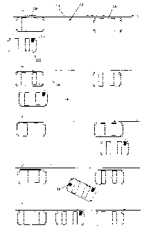
Figure 1 shows illustrates how the present invention would be applied to a
parking aid,
5
Figure 2 shows a 3D camera used in the present invention,
Figure 3 shows an illumination means used in the 3D camera shown in Figure 2,
10 Figure 4 shows an alternative illumination means,
Figure 5 shows a 3D camera with two detector viewpoints,
Figure 6 shows a mask that can be used with a variant of the 3D camera
technology to
15 produce a simple proximity sensor or optical bumper, and
Figure 7 shows a fork lift truck with a control system of the present
invention.
One embodiment of the movement control sensor of the present invention is a
parking
20 aid for vehicles such as road vehicles. Referring to figure 1 a a car 102
is shown that
wants to park in a parking space generally indicated 104. The space is defined
in this
instance by parked vehicles 106 and 108 and the kerb 110 and the parking
manoeuvre is
a reverse parallel parking manoeuvre. However the invention is equally
applicable to
other parking arrangements such as parking in a garage.
The driver positions the car so that it is ready to drive past the parking
space and
activates the parking aid. This may entail indicating which side of the
vehicle the
relevant space is on. In some arrangements though there may be no need to
activate
the data acquisition step - this may be automatically performed continuously
as part of
general monitoring of the environment,
In any case when the parking aid is ready to acquire data the driver drives
past the
space as indicated in Figure 1 b. At least one sideways looking three-
dimensional
imaging camera unit 112 takes a plurality of images of the view from the side
of the car
as the car travels past the space. The field of view of the imager is
indicated 114 and it
CA 02556996 2006-08-21
WO 2005/085904 PCT/GB2005/000843
26
can be seen that the successive images will give data about the range of
parked car 106,
the kerb 110 and parked car 108.
The parking aid processor takes all the data captured by the three-dimensional
camera
unit 112 and, as each image is acquired, records the relative position of the
car by
determining the amount of travel since the data acquisition was started. The
processor
could measure the amount of travel by incorporating a location sensor such as
a GPS
system but conveniently just links into the existing vehicle odometer system
which works
by measuring wheel rotation. For a parking aid it is usual that the vehicle
will travel in
generally a straight line when passing the space but any movement of the
steering wheel
could also be measured. Existing car systems tend to do these things already
so
integrating the parking sensor into the vehicle is relatively easy.
The processor of the 3D camera unit 112 not only works on the range data
captured by
the 3D camera as it traverses the space but also applies stereo imaging
techniques to
process the data from different frames. As the car moves the viewpoint of the
camera
changes and hence objects in the scene will move in the captured images. As
the skilled
person will appreciate, range information and location information about
objects in a
scene can be found using stereo imaging techniques. As the edges of objects
often
show the most contrast in an image and move between the two images stereo
processing techniques are good at locating the edges of objects. Combined with
the
range information collected by the 3D camera the location of objects in the
scene can
then be modelled.
Movement of the car provides frame to frame images that can be processed using
stereo
processing techniques with a horizontal separation. It can also be useful to
generate
stereo information by looking at images separated along the vertical, for
instance this can
help in locating the kerb. The 3D camera unit 112 may therefore comprise two
individual
3D cameras, or a 3D camera arrangement with two detectors, both looking
generally in
the same direction but having a certain predefined separation along a vertical
axis.
The processor of the 3D camera unit therefore captures all the data from the
scene and
applies stereo processing techniques to identify the edges of objects in the
scene. The
range data is also used to help identify objects and the fill out the surface
contours of the
objects. In this way the processor can quickly generate a model of the parking
space
and the car in relation to it.
CA 02556996 2006-08-21
WO 2005/085904 PCT/GB2005/000843
27
Once the car has passed the space, Figure 1 c, the parking aid could indicate
that it has
acquired enough information or the driver could. indicate that the data
acquisition step is
finished. The model is then finalised using all the collected information.
Once the
complete model is available the processor may calculate one or more parking
solutions.
These could be presented to the driver by means of a visual display on the
vehicle
dashboard, for instance an animated sequence showing the proposed parking
solution,
and the driver could select the desired option as required or confirm that the
parking step
should proceed.
In a purely aiding system the processor may then relay instructions to the
driver via an
interface. For instance the processor could generate a series of instructions
which are
relayed to the driver via a computer generated speech module telling the
driver when to
reverse, when and how to steer etc. This could be aided by a visual display
giving an
indication of whether the car is on the right course.
During the parking step, Figure 1 d, the processor monitors travel of the car
and the 3D
camera also monitors the environment to constantly refine the parking model.
An
additional 3D camera on the rear of the car 116 also monitors the rear of the
vehicle to
provide more information about the location of the car 2 in relation to the
parked vehicles.
These sensors also look for any changes to the environment, for instance a
pedestrian or
animal moving into the parking space or one of the parked cars moving. In this
case a
suitable warning may be activated and/or all movement of the car may be
halted.
In an automated parking system the processor actually controls a drive unit
which moves
the car from the position shown in Figure 1 c to park the vehicle by applying
the
appropriate power and steering necessary. The driver maintains the ability to
override at
any time but, if not, the car will park itself- Figure 1e. Again feedback from
the 3D
cameras 112 and 116 is used to constantly update the model of the environment
and the
car's relation thereto and to update the parking solution as required.
Thus the present invention provides a movement control system which can be
used in
aiding parking or even providing automated parking. The invention could
however also
be used as a safety monitor for ali driving situations. In particular, blind
spot detection for
lorries and cars is relevant here. For instance 3D cameras could be located at
all four
CA 02556996 2006-08-21
WO 2005/085904 PCT/GB2005/000843
28
corners of the vehicle to provide reasonable all round coverage of the
environment
around the vehicle. Locating the 3D cameras in the light clusters of vehicles
may give
appropriate coverage for a general driving aid system. Such a driving aid
system could
be used to monitor the range to vehicles either in front or behind of the car
in question
and provide warnings if suitable safety limits for the relevant speed are
breached. In
emergency situations the vehicle could even take preventative measures, for
instance
applying the brakes to prevent collision or even steering the vehicle away
from an impact
into an area determined to be free of any obstacles.
Although described above with reference to cars the invention is applicable to
use on any
vehicle which needs manoeuvring and in which there is danger of collision, for
instance
in manoeuvring aircraft in airports or lifting vehicles in warehouses etc. The
invention
would also allow lifting vehicles to determine how best to manipulate an
object, for
instance to pick up a pallet bearing a load in a warehouse and/or to deposit
it
appropriately. The same principles of the invention could also be used in
guiding robotic
arms etc.
The 3D camera used is a compact camera with high resolution, good range
accuracy
and real time processing of ranges. The camera used is that described in co-
pending
patent application PCT/GB2003/004898 published as WO 2004/044525 the contents
of
which is hereby incorporated by reference hereto.
Figure 2 shows a suitable 3D imaging camera. A two dimensional spot projector
22
projects an array of spots 12 towards a scene. Detector 6 looks towards the
scene and
detects where in the scene the spots are located. The position of the spots in
the scene
depends upon the angle the spot makes to the detector which depends upon the
range
to the target. Thus by locating the position of the spot in the scene the
range can be
determined by.processor 7.
The present invention uses a two dimensional array of spots to gain range
information
from the whole scene simultaneously. Using a two dimensional array of spots
can lead
to ambiguity problems as illustrated with reference to Figure 2a. The spot
projector 22
projects a plurality of angularly separated beams 24a, 24 b (only two are
shown for
clarity). Where the scene is a flat target the image 10 the detector sees is a
square array
of spots 12. As can be seen from figure 2a though a spot appearing at a
particular
location in the scene, say that received at angle 6~, could correspond to a
first projected
CA 02556996 2006-08-21
WO 2005/085904 PCT/GB2005/000843
29
spot, that from beam 24b, being reflected or scattered from a target 8 at a
first range or a
second, different projected spot, that from beam 24a, being reflected or
scattered from a
target 14 at a more distant range. Each spot in the array can be thought of as
having a
locus in the scene of varying range. It can be seen that the locus for one
spot, arrow 26,
can overlap with the position of other spots, giving rise to range ambiguity.
One embodiment of the 3D camera avoids this problem by arranging the spot
projector
relative to the detector such that the array of spots is projected such that
the loci of
possible positions in the detected scene at varying range of adjacent spots do
not
overlap. Figure 2b therefore shows the apparatus of the present invention from
a side
elevation. It can be seen that the detector 6 and spot projector 22 are
separated in the y-
direction as well as the x-direction. Therefore the y-position of a spot in
the scene also
varies with range, which has an effect on the locus of apparent spot motion:
The
arrangement is chosen such that the loci of adjacent spots do not overlap. The
actual
locus of spot motion is indicated by arrow 28. The same effect can be achieved
by
rotating the projector about its axis.
Another way of thinking of this would be to redefine the x-axis as the axis
along which
the detector and spot projector are separated, or at least the effective
inputlexit pupils
thereof if mirrors or other diverting optical elements were used. The z-axis
is the range
to the scene to be measured and the y-axis is orthogonal. The detector
therefore forms
a two dimensional x-y image of the scene. In this co-ordinate system there is
no
separation of the detector and projector in the y-direction and so a spot
projected by the
projector at a certain angle in the z-y plane will always be perceived to be
at that angle
by the detector, irrespective of range, i.e. the spot will only appear to move
in the
detected scene in a direction parallel to the x-direction. If the array is
therefore arranged
with regard to the x-axis such that adjacent spots have different separations
in the y-
direction there will be no ambiguity between adjacent spots. Where the array
is a square
array of spots this would in effect mean tilting the array such that an axis
of the array
does not lie along the x-axis as defined, i.e. the axis by which the detector
and spot
projector are separated.
For wholly unambiguous determination of which spot is which the spot size,
inter-spot
gap and arrangement of the detector would be such that the locus of each spot
did not
overlap with the locus of any other spot. However for practical reasons of
discrimination
a large number of spots is preferable with a relatively large spot size and
the apparatus
CA 02556996 2006-08-21
WO 2005/085904 PCT/GB2005/000843
is used with a large depth of field (and hence large apparent motion of a spot
in the
scene). In practice then the loci of different spots will sometimes overlap.
As can be
seen in figure 2b the locus of projected spot 30 does overlap with projected
spot 32 and
therefore a spot detected in the scene along the line of arrow 28 could
correspond to
5 projected spot 30 at one range or projected spot 32 at a different range.
However the
difference in the two ranges will be significaht. In some applications the
ranging system
may only be used over a narrow band of possible ranges and hence within the
operating
window there may be no ambiguity. However for most applications it will be
necessary to
resolve the ambiguity. As the difference in possible ranges is relatively
large however a
10 coarse ranging technique could be used to resolve the ambiguity over which
spot is
being considered with the ranging system then providing accurate range
information
based on the location of uniquely identified spots.
In some cases it may be possible to assume a continuous, smooth surface in
which case
15 some of the possible ambiguities could be rejected on the grounds of
excessive deviation
m range.
In one embodiment spot projector 22 projects an array of square shaped spots
which is
focussed at relatively long range. If the processor sees square spots in the
detected
20 scene this means that the spots are substantially focussed and so the
detected spot
must consequently be one which is at relatively long range. However if the
observed
spot is at close range it will be substantially unfocussed and will appear
circular. A focal
length of 800mm may be typical. Thus the appearance of the spot may be used to
provide coarse range information to remove ambiguity over which spot has been
25 detected with the location of the spot then being used to provide fine
range information.
The detector 6 is a standard two dimensional CCD array, for.instance a
standard CCD
camera although a CMOS camera could be used instead. The detector 6 should
have
sufficient resolution to be able to identify the spots and the position
thereof in the scene.
30 The detector 6 may be adapted to capture a visible image as well as detect
the spots in
the scene.
The spot projector may project spots in the visible waveband which may be
detected by
a camera operating in the visible band. However the spot projector may project
spots at
other wavelengths, for instance infrared or ultraviolet. The wavelength can be
tailored for
the particular application. l~lhere the spot projector projects infrared spots
onto the
CA 02556996 2006-08-21
WO 2005/085904 PCT/GB2005/000843
31
scene the detector used is a CCD camera with four elements to each pixel
group. One
element detects red light, another blue light and a third green light. The
fourth element in
the system is adapted to detect infrared light at the appropriate wavelength.
Thus the
readout from the RGB elements can be used to form a visible image free from
any spots
and the output of the infrared elements, which effectively contains only the
infrared spots,
provided to the processor to determine range. Where spots are projected at
different
wavelengths however as will be described later the detector must be adapted to
distinguish between different infrared wavelengths, in which case a different
camera may
be preferred. The detector is not limited to working in the visible band
either. For
instance a thermal camera may be used. Provided the detector is able to detect
the
projected spots it.doesn't matter whether the detector also has elements
receiving
different wavelengths.
In order to aid spot detection and avoid problems with ambient light the spot
projector is
adapted to project a modulated signal. The processor is adapted to filter the
detected
signal at the modulation frequency to improve the signal to noise ratio. The
simplest
realisation of this principle is to use a pulsed illumination, known as
strobing or flash
illumination. The camera captures one frame when the pulse is high. A
reference frame
is also taken without the spots projected. The difference of these intensity
patterns is
then corrected in terms of background lighting offsets. In addition a third
reflectivity
reference frame could be collected when synchronised to a uniformly
illuminated LED
flashlamp which would allow a normalisation of the intensity pattern.
A suitable spot projector 22 is shown in figure 3. A light source 34 is
located adjacent an
input face of a kaleidoscope 36. At the other end is located a simple
projection lens 38.
The projection lens is shown spaced from the kaleidoscope for the purposes of
clarity but
would generally be located adjacent the output face of the kaleidoscope.
The light source 34 is an infrared emitting light emitting diode (LED). As
discussed
above infrared is useful for ranging applications as the array of projected
spots need not
interfere with a visual image being acquired and infrared LEDs and detectors
are
reasonably inexpensive. However the skilled person would appreciate that other
wavelengths and other liglit sources could be used for other applications
without
departing from the spirit of the invention.
CA 02556996 2006-08-21
WO 2005/085904 PCT/GB2005/000843
32
The kaleidoscope is a hollow tube with internally reflective walls. The
kaleidoscope
could be made from any material with suitable rigidity and the internal walls
coated with
suitable dielectric coatings. However the skilled person would appreciate that
the
kaleidoscope could alternatively comprise a solid bar of material. Any
material which is
transparent at the wavelength of operation of the LED would suffice, such as
clear optical
glass. The material would need to be arranged such that at the interface
between the
kaleidoscope and the surrounding air the light is totally internally reflected
within the
kaleidoscope. This may be achieved using additional (silvering) coatings,
particularly in
regions that may be cemented with potentially index matching cements/epoxys
etc.
Where high projection angles are required this could require the kaleidoscope
material to
be cladded in a reflective material. An ideal kaleidoscope would have
perfectly
rectilinear walls with 100% reflectivity. It should be noted that a hollow
kaleidoscope may
not have an input or output face as such but the entrance and exit to the
hollow
kaleidoscope should be regarded as the face for the purposes of this
specification.
The effect of the kaleidoscope tube is such that multiple images of the LED
can be seen
at the output end of the kaleidoscope.
The dimensions of the device are tailored for the intended application.
Imagine that the
LED emits light into a cone with a full angle of 90°. The number of
spots viewed on
either side of the centre, unreflected, spot will be equal to the kaleidoscope
length
divided by its width The ratio of spot separation to spot size is determined
by the ratio of
kaleidoscope width to LED size. Thus a 200Nm wide LED and a kaleidoscope 30mm
long by 1 mm square will produce a square grid of 61 spots on a side separated
by five
times their width (when focussed). The spot projector may typically be a few
tens of
millimetres long and have a square cross section with a side in the range of 2
to 5mm
long, say 3, to 4mm square. For typical applications the spot projector is
designed to
produce an array of 40 x 30 spots or greater to be projected to the scene.
A,40 by 30
array generates up to 1200 range points in the scene although 2500 range
points may be
preferred with the use of intersection lines allowing up to 10,000 range
points.
Projection lens 38 is a simple singlet lens arranged at the end of
kaleidoscope and is
chosen so as to project the array of images of the LED 34 onto the scene. The
projection geometry again can be chosen according to the application and the
depth of
field required but a simple geometry is to place the array of spots at or
close to the focal
plane of the lens. The depth of field of the projection system is important as
it is
CA 02556996 2006-08-21
WO 2005/085904 PCT/GB2005/000843
33
preferable to have a large depth of field to enable the ranging apparatus to
accurately
range to objects within a large operating window. A depth of field of 150mm
out to
infinity is achievable and allows useful operating windows of range to be
determined.
As mentioned LED 34 may be square in shape and projection lens 38 could be
adapted
to focus the array of spots at a distance towards the upper expected range
such that the
degree of focus of any particular spot can yield coarse range information.
A spot projector as described figs several advantages. The kaleidoscope is
easy and
inexpensive to manufacture. LEDs are cheap components and as the kaleidoscope
efficiently couples light from the LED to the scene a relatively low power
source can be
used. The spot projector as described is therefore an inexpensive and
reasonably robust
component and also gives a large depth of focus which is very useful for
ranging
applications. A kaleidoscope based spot projector is thus preferred for the
present
invention. Further the spot projector of the present invention can be arranged
so as to
effectively have no specific axis. All beams of light emitted by the spot
projector pass
through the end of the kaleidoscope and can be thought of as passing through
the centre
of the output face. Where projection lens 38 is a hemispherical lens with its
axis of
rotation coincident with the centre of the output face then all beams of light
appear to
originate from the output face of the kaleidoscope and the projector acts as a
wide angle
projector.
The skilled person would appreciate however that other spot projectors could
be used to
generate the two dimensional array. For instance a laser could be used with a
diffractive
element to generate a diffraction pattern which is an array of spots.
Alternatively a
source could be used with projection optics and a mask having an array of
apertures
therein. Any source that is capable of projecting a discrete array of spots of
light to the
scene would suffice, however the depth of field generated by other means, LED
arrays,
microlens arrays, projection masks etc., has generally been found to be very
limiting in
performance.
An apparatus as shown in Figure 2 was constructed using a spot projector as
shown in
figure 3. The spot projector illuminated the scene with an array of 40 by 30
spots. The
operating window was 60° full angle. The spots were focussed at a
distance of 1 m and
the ranging device worked well in the range 0.5m to 2m. The detector was a 308
kpixel
CA 02556996 2006-08-21
WO 2005/085904 PCT/GB2005/000843
34
(VGA) CCD camera. The range to different objects in the scene were measured to
an
accuracy of 0.5mm at mid range.
Before the apparatus as described above can be used to produce range data, it
must
first be calibrated. In principle, the calibration can be generated .from the
geometry of the
system. In practice, it is more convenient to perform a manual calibration.
This allows for
imperfections in construction and is likely to produce better results.
After calibration the system is ready to determine range. The range finding
algorithm
consists of four basic stages. These are:
1 Normalise the image
2 Locate the spots in the image.
3 Identify the spots
4 Calculate range data
Normalisation
Since the camera has been filtered to select only light from the kaleidoscope,
there
should be a very low level of background light in the image. Therefore, any
regions that
are bright in comparison to the local background can be reasonably expected to
be
spots. However, the relative brightnesses of different spots will vary
according to the
range, position and reflectivity of the target. It is therefore convenient as
a first step to
normalise the image to remove unwanted background and highlight the spots.
The normalisation procedure consists of calculating the 'average' intensity in
the
neighbourhood of each pixel, dividing the signal at the pixel by its local
average and then
subtracting unity. If the result of this calculation is less than zero, the
result is set to zero.
Spot location
Spot location consists of two parts. The first is finding the spot. The second
is
determining its centre. The spot-finding routine maintains two copies of the
normalised
image. One copy (image A) is changed as more spots are found. The other (image
B) is
fixed and used for locating the centre of each spot.
As it is assumed that all bright features in the normalised images are spots,
the spots
can be found simply by locating all the bright regions in the image. The first
spot is
assumed to be near the brightest point in image A. The coordinates of this
point are
used to determine the centre of the spot and an estimate of the size of the
spot (see
oelow). The intensity in the region around the spot centre (based on the
estimated spot
CA 02556996 2006-08-21
WO 2005/085904 PCT/GB2005/000843
size) is then set to zero in image A. The brightest remaining point in image A
is then
used to find the next spot and so on.
The spot-finding algorithm described above will find spots indefinitely unless
extra
5 conditions are imposed. Three conditions have been identified, which are
used to
terminate the routine. The routine terminates when any of the conditions is
met. The
first condition is that the number of spots found should not exceed a fixed
value. The
second condition is that the routine should not repeatedly find the same spot.
This
occurs occasionally under some lighting conditions. The third condition is
that the
10 intensity of the brightest point remaining in image A falls below a
predetermined
threshold value. This condition prevents the routine from finding false spots
in the
picture noise. Usually the threshold intensity is set to a fraction (typically
20%) of the
intensity of the brightest spot in image B.
15 The centre of each spot is found from image B using the location determined
by the spot-
finding routine as a starting point. A sub-image is taken from image B,
centred on that
point. The size of the sub-image is chosen to be slightly larger than the size
of a spot.
The sub-image is reduced to a one-dimensional array by adding the intensity
values in
each column. The array (or its derivative) is then correlated with a gaussian
function (or
20 it's derivative) and the peak of the correlation (interpolated to a
fraction of a pixel) is
defined as the centre of the spot in the horizontal direction. The centre of
the spot in the
orthogonal direction is found in a similar manner by summing rows in the sub-
image
instead of columns.
25 If the centre of the spot determined by the procedure above is more than
two pixels away
from the starting point, the procedure should be repeated iteratively, using
the calculated
centre as the new starting point. The calculation continues until the
calculated position
remains unchanged or a maximum number of iterations is reached. This allows
for the
possibility that the brightest point is not at the centre of the spot. A
maximum number of
30 iterations (typically 5) should be used to prevent the routine from hunting
in a, small
region. The iterative approach also allows spots to be tracked as the range to
an object
varies, provided that the spot does not move too far between successive
frames. This
feature is useful during calibration.
35 Having found the centre of the spot, the number of pixels in the sub-image
with an
intensity greater than a threshold value (typically 10% of the brightest pixel
in the sub-
CA 02556996 2006-08-21
WO 2005/085904 PCT/GB2005/000843
36
image) is counted. The spot size is defined as the square root of this number,
and may
be used for additional coarse range information.
The outcome of the spot locating procedure is a list of (a,b) coordinates,
each
representing a different spot.
Spot Identification
The range to each spot can only be calculated if the identity of the spot can
be
determined. The simplest approach to spot identification is to determine the
distance
from the spot to each spot track in turn and eliminate those tracks that lie
outside a pre-
determined distance (typically less than one pixel for a well-calibrated
system). This
approach may be time-consuming when there are many spots and many tracks. A
more
efficient approach is to calculate the identifier for the spot and compare it
with the
identifiers for the various tracks. Since the identifiers for the tracks can
be pre-sorted,
the search can be made much quicker. The identifier is calculated in the same
way as in
the calibration routine.
Once candidate tracks have been identified, it is necessary to consider the
position of the
spot along the track. If the range of possible distances is limited, (e.g.
nothing can be
closer than, say, 150mm or further than 2500mm) then many of the candidate
tracks will
be eliminated since the calculated range will be outside possible boundaries.
In a weif-
adjusted system, at most two tracks should remain. One track will correspond
to a short
range and the other to a much longer range.
A final test is to examine the shape of the spot in question. As described the
projector 22
produces spots that are focussed at long ranges and blurred at short ranges.
Provided
that the LEDs in the projector have a recognisable shape (such as square) then
the
spots will be round at short distances and shaped at long distances. This
should remove
any remaining range ambiguities.
Any spots that remain unidentified are probably not spots at all but unwanted
points of
light in the scene.
Range calculation
Once a spot has been identified, its range can be calculated. In order to
produce a valid
3-dimensional representation of the scene it is also necessary to calculate x
and y-
CA 02556996 2006-08-21
WO 2005/085904 PCT/GB2005/000843
37
coordinates: These can simply be derived from the camera properties. For
example, for
a camera lens of focal length f with pixel spacing p, the x- and y-coordinates
are simply
given by:
x=zaplf, y=zbplf
where a and b are measured in pixel coordinates.
The embodiment described above was adjusted so as to have minimal ambiguity
between possible spots and use focus to resolve the ambiguity. Other means of
resolving ambiguity may be employed however. In one embodiment of the
invention the
apparatus includes a spot projector generally as described with reference to
figure 3 but
in which the light source is shaped so as to allow discrimination between
adjacent spots.
Where the light source is symmetric about the appropriate axes of reflection
the spots
produced by the system are effectively identical. However where a non
symmetrically
shaped source is used adjacent spots will be distinguishable mirror images of
each
other. The principle is illustrated in figure 4.
The structured light generator 22 comprises a solid tube of clear optical
glass 56 having
a square cross section. A shaped LED 54 is located at one face. The other end
of tube
56 is shaped into a hemispherical projection lens 58. Kaleidoscope 56 and lens
58 are
therefore integral which increases optical efficiency and eases manufacturing
as a single
moulding step may be used. Alternatively a separate lens could be optically
cemented to
the end of a solid kaleidoscope with a plane output face.
For the purposes of illustration LED 54 is shown as an arrow pointing to one
corner of
the kaleidoscope, top right in this illustration. The image formed on a screen
60 is
shown. A central image 62 of the LED is formed corresponding to an unreflected
spot
and again has the arrow pointing to the top right. Note that in actual fact a
simple
projection lens will project an inverted image and so the images formed would
actually be
inverted. However the images are shown not inverted for the purposes of
explanation.
The images 64 above and below the central spot have been once reflected and
therefore
are a mirror image about the x-axis, i.e. the arrow points to the bottom
right. The next
images 66 above or below however have been twice reflected about the x-axis
and so
are identical to the centre image. Similarly the images 68 to the left and
right of the
centre image have been once reflected with regard to the y-axis and so the
arrow
appears to point to the top left. The images 70 diagonally adjacent the centre
spot have
been reflected once about the x-axis and once about the y-axis and so the
arrow
CA 02556996 2006-08-21
WO 2005/085904 PCT/GB2005/000843
38
appears to point to the bottom left. Thus the orientation of the arrow in the
detected
image gives an indication of which spot is being detected. This technique
allows
discrimination between adjacent spots but not subsequent spots.
In another embodiment more than one light source is used. The light sources
could be
used to give variable resolution in terms of spot density in the scene, or
could be used to
aid discrimination between spots, or both.
For example if more than one LED were used and each LED was a different colour
the
pattern projected towards the scene would have different coloured spots
therein. The
skilled person would appreciate that the term colour as used herein does not
necessarily
mean different wavelengths in the visible spectrum but merely that the LEDs
have
distinguishable wavelengths.
The arrangement of LEDs on the input face of the kaleidoscope effects the
array of spots
projected. and a regular arrangement is preferred. To provide a regular array
the LEDs
should be regularly spaced from each other and the distance from the LED to
the edge of
the kaleidoscope should be half the separation between LEDs.
In another embodiment an arrangement of LEDs may be used to give differing
spot
densities. For example thirteen LEDs may arranged on the input face of a
square
section kaleidoscope. Nine of the LEDs are arranged in a regular 3x3 square
grid
pattern with the middle LED centred in the middle of the input face. The
remaining four
LEDs are arranged as they would be to give a regular 2x2 grid.. The structured
light
generator can then be operated in three different modes. Either the central
LED could
be operated on its own, this would project a regular array of spots as
described above, or
multiple LEDs could be operated. For instance, the four LEDs arranged in the
2x2
arrangement could~be illuminated to give an array with four times as many
spots
produced than with the centre LED alone.
The different LED arrangements could be used at different ranges. When used to
illuminate scenes where the targets are at close range the single LED may
generate a
sufficient number of spots for discrimination. At intermediate or longer
ranges however
the spot density may drop below an acceptable level, in which case either the
2x2 or 3x3
array could be used to increase the spot density. As mentioned the LEDs could
be
different colours to improve discrimination between different spots.
CA 02556996 2006-08-21
WO 2005/085904 PCT/GB2005/000843
39
Where multiple sources are used appropriate choice of shape or colour of the
sources
can give further discrimination.
Where multiple sources are used the sources may be arranged to be switched on
and off
independently to further aid in discrimination. For instance several LEDs
could be used,
arranged as described above, with each LED being activated in turn.
Alternatively the
array could generally operate with all LEDs illuminated but in response to a
control signal
from the processor which suggests some ambiguity could be used to activate or
deactivate some LEDs accordingly.
All of the above embodiments using shaped LEDs or LEDs or different colours
can be
combined with appropriate arrangement of the detector and spot projector such
that
where the locus of a spot overlaps with another spot the adjacent spots on
that locus
have different characteristics. For example, referring back to Figure 2b it
can be seen
that the arrangement is such that the locus of spot 30 overlaps with spot 32,
i.e. a spot
detected at the position of spot 32 shown could correspond to projected spot
32 reflected
from a target at a first range or projected spot 30 reflected from a target at
a different
range. However imagine that the spot projector of figure 5 were used. It can
been seen
that if projected spot 30 were an arrow pointing to the upper right then
projected spot 32,
but virtue of its position in the array, would be an arrow pointing to the
upper left. Thus
there would be no ambiguity over which spot was which as the direction of the
arrow
would indicate which spot was being observed.
In an alternative embodiment of spot projector the light source illuminates
the
kaleidoscope through a mask. The kaleidoscope and projection lens may be the
same
as described above but the light source may be a bright LED source arranged to
illuminate the mask through a homogeniser. The homogeniser simply acts to
ensure
uniform illumination of the mask and so may be a simple and relatively
inexpensive
plastic light pipe. Alternatively larger LEDs, which can be placed less
accurately, may be
an efficient and low cost solution.
The mask is arranged to have a plurality of transmissive portions, i.e.
windows, so that
only part of the light from the LED is incident on the input face of the
kaleidoscope. Each
aperture in the mask will act as a separate light source in the same manner as
described
CA 02556996 2006-08-21
WO 2005/085904 PCT/GB2005/000843
above and so the kaleidoscope wiN replicate an image of the apertures in the
mask and
project an array of spots onto the scene.
A mask may be fabricated and accurately aligned with respect to the
kaleidoscope more
5 easily than an LED array which would require small LEDs. Thus the
manufacture of the
spot projector may be simplified by use of a mask. The transmissive portions
of the
mask may be shaped so as to act as shaped light sources as described above.
Therefore the mask may allow an array. of spots of different shapes to be
projected and
shaping of the transmissive portions of the mask may again be easier than
providing
10 shaped light sources.
Further the different transmissive portions of the mask may transmit at
different
wavelengths, i.e. the windows may have different coloured filters.
15 Some of the transmissive windows may have a transmission characteristic
which can be
modulated, for instance the mask may comprise an electro-optic modulator.
Certain
windows in the mask may then be switched from being transmissive to non
transmissive
so as to deactivate certain spots in the projected array. This could be used
in a similar
fashion to the various arrays described to give different spot densities or
could be used
20 to deactivate certain spots in the array so as to resolve a possible
ambiguity.
In a further embodiment light sources are arranged at different depths within
the
kaleidoscope. The angular separation of adjacent beams from the kaleidoscope
depends upon the ratio between the length and width of the kaleidoscope as
discussed
25 above. For instance the kaleidoscope tube may be formed from two pieces of
material.
A first LED is located at the input face of the kaleidoscope as discussed
above. A
second LED is located at a different depth within the kaleidoscope, between
the two
sections of the kaleidoscope. The skilled person would be well aware of how to
join the
two sections of kaleidoscope to ensure maximum efficiency and locate the
second LED
30 between the two sections.
The resulting pattern contains two grids with different periods, the grid
corresponding to
the second LED partially obscuring the grid corresponding to the first LED.
The degree
of separation between the two spots will vary with distance from the centre
spot. The
35 degree of separation or offset of the two grids could then be used to
identify the spots
CA 02556996 2006-08-21
WO 2005/085904 PCT/GB2005/000843
41
uniquely. The LEDs could be different colours as described above to improve
discrimination.
It should be noted that the term spot should be taken as meaning a point of
light which is
distinguishable. It is not intended to limit to an entirely separate area of
light. For
instance a cross shaped LED may be used on the input face of the kaleidoscope.
The
LED extends to the side walls of the kaleidoscope and so the projected pattern
will be a
grid of continuous lines. The intersection of the lines provides an
identifiable area or spot
which can be located and the range determined in the same manner as described
above.
Once the range to the intersection has been determined the range to any point
on the
line passing through that intersection can be determined using the information
gained
from the intersection point. Thus the resolution of the system is greatly
magnified. Using
the same 40x30 projection system described above but with the LED arrangement
shown in figure 10 there are 1200 intersection points which can be identified
to a system
with far more range points. The apparatus could be used therefore with the
processor
arranged to identify each intersection point and determine the range thereto
and then
work out the range fo each point on the connecting lines. Alternatively the
cross LED
could comprise a separate centre portion which can be illuminated separately.
Illumination of the central LED portion would cause an array of spots to be
projected as
described earlier. Once the range to each spot had been determined the rest of
cross
LED could be activated and the range to various points on the connecting lines
determined. Having the central portion only illuminated first may more easily
allow
ambiguities to be resolved based on shaped of the projected spots. An
intersecting array
of lines can also be produced using a spot projector having a mask.
As mentioned above it can be beneficial to view the scene from two different
viewpoints.
Figure 5 shows a system where two CCD cameras 6, 106 are used to look at the
scene.
Spot projector 22 may be any of the spot projectors described above and
projects a
regular array of spots or crosses. CCD camera 6 is the same as described above
with
respect to figure 2. A second camera 106 is also provided which is identical
to camera 6.
A beamsplitter 104 is arranged so as to pass some light from the scene to
camera 6 and
reflect some light to camera 106. The arrangement of camera 106 relative to
beamsplitter 104 is such that there is a small difference 108 in the effective
positions of
the two cameras. Each camera therefore sees a slightly different scene. If the
camera
positions ~rere sufficiently far removed the beamsplitter 104 could be omitted
and both
CA 02556996 2006-08-21
WO 2005/085904 PCT/GB2005/000843
42
cameras could be oriented to look directly towards the scene but the size of
components
and desired spacing may not allow such an arrangement.
The output from camera 6 could then be used to calculate range to the scene as
described above. Camera 106 could also be used to calculate range to the
scene. The
output of each camera could be ambiguous in the manner described above in that
a
detected spot may correspond to any of one of a number of possible projected
spots at
different ranges. However as the two cameras are at different spacings the set
of
possible ranges calculated for each detected spot will vary. Thus for any
detected spot
only one possible range, the actual range, will be common to the sets
calculated for each
camera.
When camera 6 is located with a very small baseline, i.e. separation of line
of sight, from
the spot projector the corresponding loci of possible positions of spots in
the scene at
different ranges are small. Referring back to figure 2a it can be seen that if
the
separation from the detector 6 to the spot projector 22 is small the apparent
movement in
the scene of a spot at different ranges will not be great. Thus the locus will
be small and
there may be no overlap between loci of different spots in the operating
window, i.e. no
ambiguity. However a limited locus of possible positions means that the system
is not as
accurate as one with a greater degree of movement. For a system with
reasonable
accuracy and range a baseline of approximately 60mm would be typical.
Referring to
figure 9 then if camera 6 is located close to the line of sight of the spot
projector the
output from camera 6 would be a non ambiguous but low accuracy measurement.
Camera 106 however may be located at an appropriate baseline from the spot
projector
22 to give accurate results. The low accuracy readings from the output from
camera 6
could be used to resolve any ambiguity in the readings from camera 106.
Alternatively the outputs from the two camera themselves could be used to give
coarse
ranging. If the arrangement is such that the baseline between the cameras is
small, say
about 2mm, the difference in detected position of a spot in the two cameras
can be used
to give a coarse estimate of range. The baseline between either camera and the
projector may be large however. The advantage of this configuration is that
the two
cameras are looking at images with very small differences between them. The
camera
to projector arrangement needs to determine spot location by correlation of
the
recovered spot with a stored gaussian intensity distribution to optimise the
measurement
of the position of the spot. This is reasonable but never a perfect match as
the spot
CA 02556996 2006-08-21
WO 2005/085904 PCT/GB2005/000843
43
sizes change with range and reflectivity may vary across the spot. Surface
slope of the
target may also effect the apparent shape. The camera to camera system looks
at the
same, possibly distorted spot, from two viewpoints which means that the
correlation is
always nearly a perfect match. This principle of additional camera channels to
completely
remove ambiguity or add information can be realised to advantage using cameras
to
generate near orthogonal baselines and/or as a set of three to allow two
orthogonal
stereo systems to be generated. The combination of a spot projecting 3D camera
with a
feature detecting stereo/trinocular camera can provide a powerful combination.
For some applications, or in some modes of operation, full range information
about the
scene may not be required and all that might be needed is a proximity alert.
In which
case the 3D camera described above may be used without the need for any
intensive
processing to produce a model of the environment. Simply giving warnings about
objects being within certain range limits may be sufficient. For instance as a
simple
sensor for preventing collision, e.g. for aircraft wingtips, it may be
sufficient to use a 3D
camera of the present invention simply indicate the range to the nearest
object or give an
indication if an object is getting close to the wingtip, e.g. an audible
bleeping alarm with a
frequency dependent on range. In which case the processor may simply be
adapted to
determine range and either give an indication of the closest range or generate
a warning
signal based on certain threshold ranges. Alternatively the 3D camera could be
used as
part of a system operable in two modes, a simple movement mode where all that
is
needed is collision avoidance type information and an interaction mode where
full 3D
information is needed to allow interaction with the environment, such as
manipulating
objects.
Where only a simple proximity sensor is required a variation of the 3D camera
technology described above can be used. This variant has a similar spot
projector and
detector as shown in Figure 2 but a mask is placed in front of the detector.
The mask
has apertures therein to ensure that the detector can only see spots at
certain ranges.
As can be seen from Figure 2 a spot in the scene appears at different
positions in the
scene as different ranges. The apertures in the mask can be positioned so that
a spot
only appears in the aperture, and hence appears to the detector, when
reflected from a
target at a certain range. Therefore the mere presence of a spot gives an
indication of a
range bracket and so range threshold information is given without the need for
any
processing. Thus processor 7 in Figure 2 can be replaced with a simple
threshold
detector. A proximity sensor of this type is described in co-pending
application no
CA 02556996 2006-08-21
WO 2005/085904 PCT/GB2005/000843
44
PCT/GB2003I004861 published as WO 2004/044619. A more flexible solution does
not
actually require the presence of a physical mask. A binary mask can be
programmed
which is multiplied with the bitmap image output by the detector array to
generate the
same effect. The multiplication is a very simple step which requires minimal
processing
and the result still allows very simple processing to be applied. For the
purposes of this
specification a mask shall be taken to mean either a physical optical barrier
or notional
mask applied to the detector output.
A mask that allows discrimination between several groups of ranges is shown in
figure 6.
The mask is a sheet of opaque material 44 having an array of apertures
therein. Four
apertures 56a - d are shown for clarity although in reality the mask may be
made up of
repeating groups of these apertures. The apertures are sized and shaped so
that each
aperture could show a spot reflected from a target at a predetermined range.
However
the apertures are differently sized and are extended by different amounts in
the direction
of apparent movement of the spots in the scene with varying range. Figures 6a
to 6e
show the positions of four spots 58 a - d in the projected array reflected
from a target at
progressively closer range.
In Figure 6a the target is far away and none of the spots 58 a - d are visible
through the
apertures. If the target moves closer however spot 58a becomes visible through
aperture 56a. None of the other spots 58 b - d are visible through the other
apertures
however. In Figure 5c the target has moved closer still and now spots 58a and
58b are
visible through their respective apertures 56a and 56b but the other two spots
are not yet
visible. Figures 6d and 6e shows that as the target moves closer still spots
58c becomes
visible followed by spot 58d.
It can therefore be seen that the detector will see five distinct intensity
levels as a target
moves closer corresponding to no spots being visible or one, two, three or
four spots
being visible. Therefore the different intensity levels could be used to give
an indication
that a target is within a certain range boundary. Note that this embodiment,
using a
discriminating threshold level to determine the range, will only generally be
appropriate
where the targets are known to be of standard reflectivity and will fill the
entire field of
view at all ranges. If targets were different sizes a small target may
generate a different
intensity to a larger target and a more reflective target would generate a
greater intensity
than a less reflective one.
CA 02556996 2006-08-21
WO 2005/085904 PCT/GB2005/000843
Where target consistency is not known several detectors could be used, each
having a
mask arranged so as to pass light reflected or scattered from spots at
different ranges,
i.e. each detector would have a single comparison to determine whether an
object was
within a certain range but the range for each detector could be different.
5
Alternatively the embodiment described with reference to figure 6 could be
used with a
means of determining which spots contribute to the overall intensity on the
detector. This
could be achieved by modulating the spots present in the scene. For instance
imagine
each of the four spots in figures 6a - a was transmitted at a different
modulated
10 frequency. The signal from the detector would then have up to four
different frequency
components. The detected signal could then be processed in turn for each
frequency
component to determine whether there is any signal through the corresponding
family of
apertures. In other words if spot 58a were modulated at frequency f~
identification of a
signal component in the detected signal at f, would indicate that a target was
close
15 enough that a spot appeared in aperture 56a. Absence of frequency component
f2
corresponding to spot 58b would mean that the situation shown in figure 6b
applied.
Thus could be detected irrespective of whether an object is large or small or
reflective or
not as it is the detection of the relevant frequency component which is
indicative of
range.
Using a spot projector as shown in figure 3 to produce such a modulated output
would
simply involve replacing the single LED 34 with a row of 4 LEDs each modulated
at a
different frequency. Modulating the frequency in this way thus allows
incremental range
discrimination but reduces the density of coverage to the scene as each spot
can only be
used for one of the possible ranges. Alternatively where an input mask is used
for the
input to the kaleidoscope the mask may comprise a plurality of windows each
window
comprising a modulator operating at a different frequency.
Figure 7 shows a fork lift truck 70 having two 3D cameras mounted thereon. A
first
camera 72 is mounted on the top of the truck and is directed ~to look at the
area in front of
the truck. A second camera 74 is mounted towards the base of the truck looking
forward. The fork lift truck is automated and is controlled by controller 76
which can
operate the truck in two modes.
The first mode is a movement mode and is used for moving the truck from one
specified
location to another, for instance if a particular item from a warehouse is
needed a signal
CA 02556996 2006-08-21
WO 2005/085904 PCT/GB2005/000843
46
may be sent to the truck to fetch the item and take it to a loading bay. The
controller
'. would then direct the truck from its current location to the area of the
warehouse where
the required item is stored. In movement mode the truck will be move along the
aisles in
the warehouse where no obstacles would be expected. The truck may be provided
with
an internal map of the warehouse and position locators so that the controller
can control
movement of the truck to the specified location. Therefore detailed three
dimensional
modelling of the environment is not required. However to detect any people in
the path
of the truck or to detect any obstacles such as a fallen crate the three
dimensional
cameras operate in proximity sensor mode as described above allowing fast
identification of any possible obstacles. In movement mode the top mounted
camera 72
has a mask applied (a binary mask applied to the output) such that spots
reflected from a
level floor in front of the truck appear in the apertures of the mask. Any
significant
deviation in floor level or obstacle in the path of the projected spots will
cause the
reflected spots to move to a masked part of the scene and the change in
intensity can be
detected. The lower camera 74 is masked so that for a clear path no spots are
visible
but if an object is v~iithin say 0.5m of the truck spots will appear in the
unmasked areas.
Again this can be detected by a simple change in intensity.
Once the truck arrives at its location the controller switches to interaction
mode and a
mask is no longer applied to the output of the two cameras and full processing
of the
scene is applied. Each camera 72, 74 comprises a spot projector and two
detectors
spaced apart along the horizontal axis allowing for three dimensional ranging
and stereo
processing techniques to be applied. The vertical separation of the two
cameras also
allows for stereo processing in the vertical sense. The edges of the target
object and
features such as holes in the pallet can be identified. If necessary the
controller may
move the truck past the target area to give other viewpoints to complete the
model.
Once the model is complete the controller can set the forks of the truck to
the right height
and manoeuvre the truck to engage with the object and lift it clear. Once the
object is
securely on the lifting platform the controller may switch back to movement
mode and
move the truck to the loading area.
At the loading area the controller switches again to interaction mode,
acquires a model of
the area and deposits the object according to its original instructions.
If an obstacle is encountered on the way in movement mode the controller may
adopt
various strategies. It may stop the truck, sound an audible alarm and wait a
short time to
CA 02556996 2006-08-21
WO 2005/085904 PCT/GB2005/000843
47
see if the obstacle moves - that is a person moves out of the way - in which
case the
truck can continue its journey. If the obstacle does not move it may be
assumed to be a
blockage, in which case the truck may send a notification signal to a control
room and
determine another route to its destination or determine if a route past the
obstacle exists,
possibly by switching to interaction mode to model the blockage.