Language selection

Search

Patent 2557331 Summary

Third-party information liability

Some of the information on this Web page has been provided by external sources. The Government of Canada is not responsible for the accuracy, reliability or currency of the information supplied by external sources. Users wishing to rely upon this information should consult directly with the source of the information. Content provided by external sources is not subject to official languages, privacy and accessibility requirements.

Claims and Abstract availability

Any discrepancies in the text and image of the Claims and Abstract are due to differing posting times. Text of the Claims and Abstract are posted:

  • At the time the application is open to public inspection;
  • At the time of issue of the patent (grant).
(12) Patent: (11) CA 2557331
(54) English Title: FRONT LOADING LOCK ASSEMBLY
(54) French Title: ENSEMBLE VERROU A CHARGEMENT FRONTAL
Status: Granted and Issued
Bibliographic Data
(51) International Patent Classification (IPC):
  • E05B 9/04 (2006.01)
(72) Inventors :
  • NAKASONE, FRANKLIN T. (United States of America)
(73) Owners :
  • ASSA ABLOY AMERICAS RESIDENTIAL INC.
(71) Applicants :
  • ASSA ABLOY AMERICAS RESIDENTIAL INC. (United States of America)
(74) Agent: SMART & BIGGAR LP
(74) Associate agent:
(45) Issued: 2012-12-04
(86) PCT Filing Date: 2005-03-01
(87) Open to Public Inspection: 2005-09-15
Examination requested: 2010-02-25
Availability of licence: N/A
Dedicated to the Public: N/A
(25) Language of filing: English

Patent Cooperation Treaty (PCT): Yes
(86) PCT Filing Number: PCT/US2005/006449
(87) International Publication Number: WO 2005085566
(85) National Entry: 2006-08-24

(30) Application Priority Data:
Application No. Country/Territory Date
10/790,964 (United States of America) 2004-03-02

Abstracts

English Abstract


A lock assembly includes a housing, a core assembly and a retainer. The
housing includes a housing retainer groove located generally transverse to an
axis defined by a bore through the housing, which corresponds with a core
retainer groove. When the core assembly is mounted within the bore, the
retainer groves are aligned. The retainer is inserted into the grooves such
that a bridge portion of the retainer is engaged by an engagement feature to
secure the retainer and thereby mount the core assembly into the housing.


French Abstract

L'invention concerne un ensemble verrou comportant un boîtier, un ensemble central et un dispositif de retenue. Le boîtier comporte une rainure de retenue de boîtier située d'ordinaire transversalement par rapport à un axe défini par un trou traversant le boîtier, qui correspond à une rainure de retenue centrale. Lorsque l'ensemble central est placé à l'intérieur du trou, les rainures de retenue sont alignées. Le dispositif de retenue est introduit dans les rainures de façon qu'une partie pont du dispositif de retenue vienne en prise avec une caractéristique de contact pour fixer le dispositif de retenue et placer l'ensemble central à l'intérieur du boîtier.

Claims

Note: Claims are shown in the official language in which they were submitted.

CLAIMS
1. A lock assembly comprising:
a housing which defines an axis, said housing including a retainer
engagement feature extending from said housing and a housing
retainer groove;
a core assembly receivable within said housing along said axis; and
a retainer having a first leg, a second leg and a bridge portion between
said first leg and said second leg, said bridge portion having an
aperture located there through, said retainer engageable with said
housing retainer groove at an angle not perpendicular to said axis
to initially pass over said retainer engagement feature extending
from said housing during insertion of the retainer into the housing
retainer groove and said core assembly transverse said axis to
retain said core assembly within said housing said retainer
engagement feature is engageable with said aperture to retain
said retainer within said housing.
2. The lock assembly as recited in claim 1, wherein said retainer engagement
feature comprises an angled detent.
3. A front loading lock assembly comprising:
a housing which defines an axis, said housing including a retainer
engagement feature extending from said housing;
a core assembly receivable within said housing along said axis, said core
assembly comprising a flange which engages said housing to
locate said core assembly at a predetermined distance along said
axis; and
a retainer having a first leg, a second leg and a bridge portion between
said first leg and said second leg, said bridge portion having an
aperture located there through, said retainer engageable with said
housing and said core assembly to retain said core assembly
within said housing, said retainer receivable with a housing
retainer groove at an angle not perpendicular to said axis to
6

initially pass over said retainer engagement feature during
insertion of the retainer into the housing retainer groove and a
core assembly retainer groove transverse said axis wherein said
retainer engagement feature is engageable with said aperture to
retain said retainer within said housing.
4. The front loading lock assembly as recited in claim 3, wherein said
retainer
engagement feature comprises an angled detent,
5. A method of mounting a core assembly within a housing of a lock assembly
comprising the steps of:
(a) inserting the core assembly within a bore in the housing along an axis;
(b) aligning a housing retainer groove and a core assembly retainer groove;
(c) inserting a retainer into the housing retainer groove to initially pass
over a
retainer engagement feature extending from the housing during insertion
of the retainer into the housing retainer groove and the core assembly
retainer groove transverse the axis; and
(d) selectively securing the retainer to the housing by biasing an engagement
detent extending from the housing at least partially through an aperture in
the retainer.
6. A lock assembly comprising:
a housing which defines an axis, said housing including a retainer
engagement feature;
a core assembly receivable within said housing along said axis; and
a retainer engageable with said housing and said core assembly
transverse said axis to retain said core assembly within said
housing, said retainer includes a first leg, a second leg and a
bridge portion between said first leg and said second leg, said
bridge portion including an aperture engageable with said retainer
engagement feature to retain said retainer within said housing.
7

7. A front-loading lock assembly comprising:
a housing which defines an axis, said housing including a retainer
engagement feature;
a core assembly receivable within said housing along said axis, said core
assembly comprising a flange which engages said housing to
locate said core assembly at a predetermined distance along said
axis; and
a U-shaped retainer engageable with said housing and said core
assembly to retain said core assembly within said housing, said
retainer receivable with a housing retainer groove and a core
assembly retainer groove transverse said axis, said retainer
includes a first leg, a second leg and a bridge portion between
said first leg and said second leg, said bridge portion including an
aperture engageable with said retainer engagement feature to
retain said retainer within said housing.
8. A method of mounting a core assembly within a housing of a lock assembly
comprising the steps of:
(a) inserting the core assembly within a bore in the housing along an axis;
(b) aligning a housing retainer groove and a core assembly retainer groove;
(c) inserting a retainer into the housing retainer groove and the core
assembly retainer groove transverse the axis; and
(d) selectively securing the retainer to the housing by biasing an engagement
detent extending from the housing at least partially through an aperture in
the retainer.
9. A lock assembly comprising:
a housing which defines an axis, said housing including a retainer
engagement feature extending from said housing and a housing
retainer groove, wherein said retainer engagement feature
extending from said housing extends parallel to said axis;
a core assembly receivable within said housing along said axis; and
8

a retainer engageable with said housing retainer groove to initially pass
over said retainer engagement feature extending from said
housing during insertion of the retainer into the housing retainer
groove and said core assembly transverse said axis to retain said
core assembly within said housing.
10. A front-loading lock assembly comprising:
a housing which defines an axis, said housing including a retainer
engagement feature extending from said housing, wherein said
retainer engagement feature extending from said housing extends
parallel to said axis;
a core assembly receivable within said housing along said axis, said core
assembly comprising a flange which engages said housing to
locate said core assembly at a predetermined distance along said
axis; and
a retainer engageable with said housing and said core assembly to retain
said core assembly within said housing, said retainer receivable
with a housing retainer groove to initially pass over said retainer
engagement feature during insertion of the retainer into the
housing retainer groove and a core assembly retainer groove
transverse said axis.
9

Description

Note: Descriptions are shown in the official language in which they were submitted.


CA 02557331 2006-08-24
WO 2005/085566 PCT/US2005/006449
FRONT LOADING LOCK ASSEMBLY
BACKGROUND OF THE INVENTION
The present invention relates to a lock assembly, and more particularly to
a mounting arrangement for a core assembly into a lock housing.
s Numerous types of conventional lock assemblies are utilized for various
applications. Homes and commercial establishments are protected
predominantly by key-actuated pin tumbler locks. In a typical lock, a core
assembly houses a rotational cylindrical plug having a longitudinally
extending
keyway. A driving member such as a cam is connected to the rear face of the
io plug. The driving member actuates a bolt-throwing or latch-moving
mechanism.
The interface between the plug and the core is called the shear line. A
plurality of radially extending, parallel chambers is formed in the core and
the
plug. Spring-biased pins are disposed in each chamber. Under normal
conditions, the drivers block the shear line, to prevent the plug from being
rotated
15 relative to the core. However, when a properly configured key is inserted
into the
keyway, the drivers and lower pins are moved so that the top of the lower pins
and the bottom of the drivers meet at the shear line. The plug can then be
rotated
to cause rotation of the driving member and subsequent retraction or extension
of
the bolt or latch.
2 o Locksmiths frequently rekey or replace residential or commercial locks. To
this end, interchangeable core assemblies are manufactured by various
lockmakers. Disadvantageously, the interchangeable core assemblies are
relatively complicated. Typically, the interchangeable core assembly, even
those
from a single manufacturer, is specific to a particular lock type and include
25 mounting structure specific thereto. For example, a knob lock assembly, a
lever
lock assembly, and deadbolt lock assembly each utilize a core assembly
particular to a knob, a lever, and a deadbolt respectively. Such an
arrangement
complicates rekeying and replacement of residential and commercial locks.
Accordingly, it is desirable to provide mounting arrangement for a core
3 o assembly that is readily mounted into multiple lock types.

CA 02557331 2006-08-24
WO 2005/085566 PCT/US2005/006449
SUMMARY OF THE INVENTION
The lock assembly according to the present invention includes a housing,
a core assembly, and a retainer. The housing supports and protects the core
assembly. The retainer is a generally flat U-shaped member with two legs and a
bridge portion therebetween.
The housing includes a housing retainer groove located generally
transverse to an axis defined by a bore through the housing. The housing
retainer groove corresponds with a core retainer groove. When the core
assembly is mounted within the bore, the retainer groves are aligned. The
1o retainer is inserted into the grooves such that the bridge portion is
engaged by an
engagement feature to secure the retainer into the grooves and thereby mount
the core assembly into the housing.
The present invention therefore provides an uncomplicated mounting
arrangement for a core assembly, which is readily mounted into multiple lock
types.
BRIEF DESCRIPTION OF THE DRAWINGS
The various features and advantages of this invention will become
apparent to those skilled in the art from the following detailed description
of the
currently preferred embodiment. The drawings that accompany the detailed
description can be briefly described as follows:
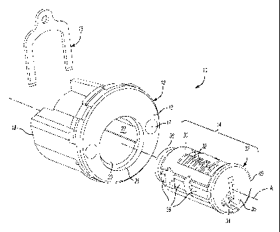
Figure 1 is a front exploded view of a lock assembly according to the
present invention;
Figure 2 is a rear exploded view of a lock assembly according to the
2 5 present invention;
Figure 3 is a planar view of a retainer;
Figure 4 is a rear perspective view of a lock assembly according to the
present invention with the retainer partially installed;
Figure 5 is an expanded view of Figure 4;
Figure 6 is a sectional view of a retainer engagement member;
2

CA 02557331 2006-08-24
WO 2005/085566 PCT/US2005/006449
Figure 7 is a rear perspective view of a lock assembly according to the
present invention with the retainer installed; and
Figure 8 is an expanded view of Figure 7.
DETAILED DESCRIPTION OF THE PREFERRED EMBODIMENT
Figure 1 illustrates a general exploded perspective view of a lock
assembly 10. The lock assembly generally includes a housing 12, a core
assembly 14 and a retainer 16. It should be understood that although a
particular
component configuration is disclosed in the illustrated embodiment, other
to arrangements will benefit from the instant invention.
The housing 12 supports and protects the core assembly 14. The housing
12 includes openings 17 for fasteners or the like to secure the housing 12 to
a
structure. Although a deadbolt housing is illustrated in the disclosed
embodiment, it should be understood that other housings for other lock
assemblies such as a lever, or knob will also benefit from the present
invention.
The housing 12 includes a front face 13 and a rear face 18. It should be
understood that relative positional terms such as "forward," "aft," "upper,"
"lower,"
"above," "below," and the like are with reference to the normal operational
attitude and should not be considered otherwise limiting. A longitudinally
extending bore 20 opens through the front and rear faces 13, 18 and defines an
axis A. Elongate, open-ended grooves 22 are formed within the bore 20
generally parallel to the axis A. The grooves 22 are preferably open through
the
front and rear face 13, 18 and are parallel to axis A. A recessed face 28
within
the front face 22 extends about the periphery of the bore 20.
The core assembly 14 includes a barrel 30 and a rotatable lock core 32.
A keyway 34 is defined in a front face 35 of the lock core 32 to permit
insertion of
a key such that the lock core 32 can be rotated to operate the lock. Operation
of
the key to pin arrangement may take various conventional forms and need not be
described in detail herein.
3

CA 02557331 2006-08-24
WO 2005/085566 PCT/US2005/006449
A core assembly extension 36 extends from the core assembly 14. The
extension 36 is preferably formed as a portion of the barrel 30 to engage the
grooves 22 to prevent relative rotation of the housing 12 and core assembly
14.
The extension 36 also assists in guiding the core assembly 14 into the bore
20.
The extension 36 may be formed in one or more portions to preferably form a
rail
structure along the longitudinal length of the core assembly 14. It should be
understood that various extension shape and arrangements will benefit from the
present invention.
An actuating member 24 is located within a rear portion 38 of the lock core
l0 32 (Figure 2) to engage an actuating plate (not shown) that extends through
a
latch bolt (not shown), which is conventional and need not described in detail
herein.
A circumferential flange 40 (Figure 2) is received within the recessed face
28 to control the axial insertion depth of the core assembly 14 into the
housing
12.
Referring to Figure 2, the housing 12 includes a housing retainer groove
42 located generally transverse to the axis A. The housing retainer groove 42
corresponds with a core assembly retainer groove 44, which is located
transverse
to axis A. The core assembly retainer groove 44 is preferably formed
transversely through the extension 36.
When the core assembly 14 is mounted within the bore 20, the retainer
groves 42, 44 are aligned (Figure 4) through interaction of the
circumferential
flange 40 and the counter bore 28. That is, the core assembly 14 is pushed
into
the bore 20 until the circumferential flange 40 engages the counter bore 28
such
that the retainer grooves 42, 44 are aligned.
Referring to Figure 3, the retainer 16 is preferably formed as a generally
flat U-shaped member. It should be understood that other shapes will also
benefit from the present invention. The retainer 16 includes a first leg 46, a
second leg 48 and a bridge portion 50 therebetween. Each leg 46, 48 preferably
include a bevel 51 at the end thereof to assist installation of the retainer
16 into
4

CA 02557331 2006-08-24
WO 2005/085566 PCT/US2005/006449
the groove 42, 44 (Figure 5). The bridge portion 50 preferably includes an
aperture 52.
Referring to Figure 4, the retainer 16 is partially inserted into the grooves
42, 44 such that the bridge portion 50 is just above a retainer engagement
feature 54. The retainer engagement feature 54 is preferably formed along a
top
portion of housing 12 and extends toward the rear face 18 thereof.
Referring to Figure 6, the retainer engagement feature 54 includes a
biased detent 56. The biased detent 56 is located parallel to axis A.
Referring to Figure 7, as the retainer 16 is pushed into the grooves 42, 44,
the bridge portion of the retainer 16 engages the detent 56. The unique shape
of
detent 56 allows the bridge portion of 16 to slide into position, resting on
feature
61. The retainer 16 is pushed into the grooves 43, 44 until the aperture 52 is
aligned with the detent 56. When the aperture 52 is aligned with the detent
56,
detent 56 secures retainer 16 into the grooves 42, 44 and thereby mounts the
core assembly 14 within the housing 12. To remove the core assembly 14, the
bridge retainer 16 is lifted at an angle allowing 52 to clear detent 56, and
the
retainer 16 is removed.
The foregoing description is exemplary rather than defined by the
limitations within. Many modifications and variations of the present invention
are
possible in light of the above teachings. The preferred embodiments of this
invention have been disclosed, however, one of ordinary skill in the art would
recognize that certain modifications would come within the scope of this
invention. It is, therefore, to be understood that within the scope of the
appended
claims, the invention may be practiced otherwise than as specifically
described.
For that reason the following claims should be studied to determine the true
scope and content of this invention.
5

Representative Drawing
A single figure which represents the drawing illustrating the invention.
Administrative Status

2024-08-01:As part of the Next Generation Patents (NGP) transition, the Canadian Patents Database (CPD) now contains a more detailed Event History, which replicates the Event Log of our new back-office solution.

Please note that "Inactive:" events refers to events no longer in use in our new back-office solution.

For a clearer understanding of the status of the application/patent presented on this page, the site Disclaimer , as well as the definitions for Patent , Event History , Maintenance Fee  and Payment History  should be consulted.

Event History

Description Date
Inactive: Recording certificate (Transfer) 2024-01-08
Inactive: Multiple transfers 2023-11-30
Change of Address or Method of Correspondence Request Received 2019-11-20
Common Representative Appointed 2019-10-30
Letter Sent 2013-03-20
Revocation of Agent Requirements Determined Compliant 2013-02-01
Inactive: Office letter 2013-02-01
Appointment of Agent Requirements Determined Compliant 2013-02-01
Revocation of Agent Request 2013-01-21
Appointment of Agent Request 2013-01-21
Appointment of Agent Requirements Determined Compliant 2013-01-16
Revocation of Agent Requirements Determined Compliant 2013-01-16
Inactive: Office letter 2013-01-14
Appointment of Agent Request 2012-12-19
Revocation of Agent Request 2012-12-19
Grant by Issuance 2012-12-04
Inactive: Cover page published 2012-12-03
Pre-grant 2012-09-25
Inactive: Final fee received 2012-09-25
Letter Sent 2012-04-03
Notice of Allowance is Issued 2012-04-03
Inactive: Approved for allowance (AFA) 2012-03-23
Amendment Received - Voluntary Amendment 2011-10-19
Inactive: S.30(2) Rules - Examiner requisition 2011-09-02
Amendment Received - Voluntary Amendment 2010-04-27
Letter Sent 2010-03-12
Request for Examination Received 2010-02-25
Request for Examination Requirements Determined Compliant 2010-02-25
All Requirements for Examination Determined Compliant 2010-02-25
Inactive: Cover page published 2006-10-23
Inactive: Notice - National entry - No RFE 2006-10-18
Letter Sent 2006-10-18
Application Received - PCT 2006-09-25
National Entry Requirements Determined Compliant 2006-08-24
Application Published (Open to Public Inspection) 2005-09-15

Abandonment History

There is no abandonment history.

Maintenance Fee

The last payment was received on 2012-02-27

Note : If the full payment has not been received on or before the date indicated, a further fee may be required which may be one of the following

  • the reinstatement fee;
  • the late payment fee; or
  • additional fee to reverse deemed expiry.

Please refer to the CIPO Patent Fees web page to see all current fee amounts.

Owners on Record

Note: Records showing the ownership history in alphabetical order.

Current Owners on Record
ASSA ABLOY AMERICAS RESIDENTIAL INC.
Past Owners on Record
FRANKLIN T. NAKASONE
Past Owners that do not appear in the "Owners on Record" listing will appear in other documentation within the application.
Documents

To view selected files, please enter reCAPTCHA code :


To view images, click a link in the Document Description column. To download the documents, select one or more checkboxes in the first column and then click the "Download Selected in PDF format (Zip Archive)" or the "Download Selected as Single PDF" button.

List of published and non-published patent-specific documents on the CPD .

If you have any difficulty accessing content, you can call the Client Service Centre at 1-866-997-1936 or send them an e-mail at CIPO Client Service Centre.


Document
Description 
Date
(yyyy-mm-dd) 
Number of pages   Size of Image (KB) 
Description 2006-08-24 5 227
Drawings 2006-08-24 4 88
Claims 2006-08-24 4 97
Representative drawing 2006-08-24 1 20
Abstract 2006-08-24 2 81
Cover Page 2006-10-23 1 42
Claims 2011-10-19 4 145
Representative drawing 2012-11-07 1 14
Cover Page 2012-11-07 1 42
Maintenance fee payment 2024-02-23 47 1,942
Notice of National Entry 2006-10-18 1 192
Courtesy - Certificate of registration (related document(s)) 2006-10-18 1 105
Reminder - Request for Examination 2009-11-03 1 118
Acknowledgement of Request for Examination 2010-03-12 1 177
Commissioner's Notice - Application Found Allowable 2012-04-03 1 163
Fees 2012-02-27 1 157
PCT 2006-08-24 1 48
Fees 2008-02-25 2 51
Correspondence 2012-09-25 3 74
Correspondence 2012-12-19 12 839
Correspondence 2013-01-14 1 25
Correspondence 2013-01-21 3 150
Correspondence 2013-02-01 1 14
Correspondence 2013-02-01 1 19