Note: Descriptions are shown in the official language in which they were submitted.
CA 02557454 2006-08-28
SYSTEM AND METHOD FOR RECOVERING CO2
BACKGROUND OF THE INVENTION
1. Field of the Invention
The present invention relates to a CO2 recovery system
and method for achieving energy saving.
2. Description of the Related Art
In recent years the greenhouse effect produced by CO2
has been pointed out as one of causes of the global warming,
and a countermeasure against it is urgently required
internationally to protect global environment. CO2 is
emitted during various human activities, including burning
of fossil fuels, and there is an increasing demand to
suppress the CO2 emission. Consequently, people have been
energetically studying means and methods for suppressing
emission of CO2 from power generation facilities such as
power plants which use an enormous amount of fossil fuels.
One of the methods includes bringing combustion exhaust gas
of boilers into contact with an amine-based C02-absorbing
solution. This method allows removal and recovery of CO2
from the combustion exhaust gas. Another method includes
storing recovered CO2, i.e., not returning the recovered
CO2 to the atmosphere.
Various methods are known for removing and recovering
1
CA 02557454 2009-01-28
28964-129
C02 from combustion exhaust gas using the C02-absorbing
solution. One of the methods includes contacting the
combustion exhaust gas with the C02-absorbing solution in an
absorption tower, heating an absorbing solution having
absorbed COZ in a regeneration tower, and releasing CO2,
regenerating the absorbing solution, and circulating the
absorbing solution recovered to the absorption tower again
to be reused. A conventional technique has been disclosed
in, for example, Japanese Patent Application Laid-Open No.
H7-51537.
SUMMARY OF THE INVENTION
It is an object of the present invention to at
least partially solve the problems in the conventional
technology.
According to an aspect of the present invention, a
CO2 recovery system including an absorption tower that
receives C02-containing gas and C02-absorbing solution, and
causes the C02-containing gas to come in contact with the
C02-absorbing solution to produce C0Z rich solution, and a
regeneration tower that receives the rich solution and
produces lean solution from the rich solution by removing C02
from the rich solution, wherein the C02 recovery system
comprises: a heating member that is provided in the
regeneration tower and that heats the rich solution in the
regeneration tower with steam generated when regenerating
the rich solution in the regeneration tower; a first lean-
solution conveying path that conveys the lean solution from
the regeneration tower to the absorption tower; a first
rich-solution conveying path that extracts the rich solution
from the regeneration tower from a first point and returns
2
CA 02557454 2009-01-28
28964-129
extracted rich solution to the regeneration tower to a
second point downstream of a third point; and a lean-
solution heat exchanger provided in the first lean-solution
conveying path and a second rich-solution conveying path and
heats the lean solution in the first lean-solution conveying
path with the extracted rich solution in the second rich-
solution conveying path.
According to another aspect of the present
invention, a CO2 recovery method including causing C02-
containing gas to come in contact with C02-absorbing solution
to produce CO2 rich solution in an absorption tower,
conveying the rich solution to a regeneration tower, and
producing a lean solution from the rich solution by removing
CO2 from the rich solution in the regeneration tower, wherein
the COz recovery method comprises: heating the rich solution
in the regeneration tower with steam generated when
regenerating the rich solution in the regeneration tower;
heating the rich solution with the lean solution produced in
the regeneration tower; extracting the lean solution from
the regeneration tower, heating extracted lean solution with
steam, and returning heated lean solution to the
regeneration tower, whereby a steam condensate is produced
from the steam due to loss of heat; and extracting the rich
solution from the regeneration tower, heating extracted rich
solution with the steam condensate, and returning heated
rich solution to the regeneration tower.
The above and other objects, features, advantages
and technical and industrial significance of this invention
will be better understood by reading the following detailed
description of presently preferred embodiments of the
invention, when considered in connection with the
accompanying drawings.
3
CA 02557454 2009-01-28
28964-129
BRIEF DESCRIPTION OF THE DRAWINGS
Fig. 1 is a schematic of a CO2 recovery system
according to a first embodiment of the present invention;
Fig. 2 is a schematic of a CO2 recovery system
according to a second embodiment of the present invention;
Fig. 3 is a schematic of a CO2 recovery system
according to a third embodiment of the present invention;
3a
CA 02557454 2006-08-28
Fig. 4 is a schematic of a COZ recovery system
according to a fourth embodiment of the present invention;
Fig. 5 is a schematic of a COz recovery system
according to a fifth embodiment of the present invention;
and
Fig. 6 is a schematic of a COZ recovery system
according to an example.
DETAILED DESCRIPTION OF THE PREFERRED EMBODIMENTS
Exemplary embodiments of the present invention are
explained below in detail with reference to the
accompanying drawings. The present invention is not to be
limited by the following embodiments and examples.
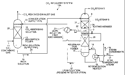
Fig. 1 is a schematic of a COZ recovery system 10A
according to a first embodiment. The COZ recovery system
10A includes an absorption tower 13 that causes COZ-
containing gas 11 containing CO2 to contact with a C02-
absorbing solution 12 to produce a C02-rich solution 14;
and a regeneration tower 15 that regenerates the rich
solution 14 to produce a lean solution (regenerated
solution) 16 by heating the rich solution 14 with steam S
generated by heating the lean solution with high
temperature steam 17 in a regeneration heater 18. The lean
solution 16 is reused in the absorption tower 13. The rich
solution 14 is introduced from a tower head via a nozzle 8
4
CA 02557454 2006-08-28
to the regeneration tower 15. The regeneration tower 15
includes a heating member 30, in which the rich solution 14
is heated with the steam S, which is generated by heating
the lean solution 16 in the regeneration heater 18 or
generated by a heat exchange in a lean-solution heat
exchanger 23. According to the first embodiment, the
heating member 30 includes a filling layer 31 to improve
contact efficiency between the rich solution 14 and the
steam S.
Conventionally, the steam S generated by heating the
lean solution 16 has been exhausted with COZ to the
outside after the steam S is used for producing the lean
solution 16. However, according to the present invention,
almost all heat of the steam S can be effectively used.
Thus, heat energy of the steam S to be exhausted to the
outside can be used by the introduced rich solution 14 in
the regeneration tower 15. As a result, energy consumption
in the regenerating system can be reduced.
According to the first embodiment, the lean-solution
heat exchanger 23 is provided in a lean-solution supply
pipe 22 that supplies the lean solution 16 from the
regeneration tower 15 to the absorption tower 13. The
lean-solution heat exchanger 23 further heats the rich
solution 14, which is heated by the steam S and extracted
via an extraction path 32, with residual heat of the lean
CA 02557454 2006-08-28
solution 16. In this manner, the heat of the lean solution
16 is reused to heat the rich solution 14.
In Fig. 1, reference numeral 8 represents a nozzle, 9
represents a chimney tray, 25 represents a filling layer
provided in the absorption tower 13, and 26 represents a
filling layer provided in the regeneration tower 15. The
heat exchanger can be any device that transfers heat of one
material to another material. The heat exchanger can be
the plate heat exchanger and the shell-and-tube heat
exchanger that are known in the art. The C02-absorbing
solution can be any medium that can absorb C02. The C02-
absorbing solution can be, for example, a hindered amine
group having alkanolamine or alcoholic hydroxyl.
Monoethanolamine, diethanolamine, triethanolamine,
methyldiethanolamine, diisopropanolamine, diglycolamine,
are the example of alkanolamine; however, it is preferable
to use monoethanolamine (MEA). The hindered amine having
alcoholic hydroxyl can be exemplified by 2-amino-2-methyl-
1-propanol (AMP), 2-(ethylamino)-ethanol (EAE), and 2-
(methylamino)-ethanol (MAE).
The C02-containing gas 11 is first cooled by a cooling
device (not shown) to about 40 C to 50 C and then supplied
to the COZ recovery device. On the other hand, the lean
solution 16 is cooled to about 40 C by another cooling
6
CA 02557454 2006-08-28
device (not shown) and then supplied to the absorption
tower 13.
The rich solution 14 output from the absorption tower
13 is maintained at about 50 C due to heat reaction and
supplied to the regeneration tower 15. The temperature of
the rich solution 14 supplied to the regeneration tower 15
is raised by about 10 C with the heat of the steam S.
Fig. 2 is a schematic of a CO2 recovery system 10B
according to a second embodiment of the present invention.
Components that are the same as those of the CO2 recovery
system 10A are assigned with the same reference numerals,
and explanation thereof is omitted.
The COZ recovery system lOB includes, in addition to
the configuration of the COZ recovery system 10A, a steam-
condensate heat exchanger 21. The steam-condensate heat
exchanger 21 further heats the rich solution 14, which has
been heated in the lean-solution heat exchanger 23, with
steam condensate 19 fed from the regeneration heater 18.
The steam-condensate heat exchanger 21 heats the rich
solution 14 with the residual heat of the steam condensate
19 and introduces the heated rich solution 14 into the
regeneration tower 15. Thus, because the residual heat of
the steam condensate 19 having been once used in the
regeneration heater 18 is reused, the energy consumption in
7
CA 02557454 2006-08-28
the regenerating system can be further reduced compared
with that of the first embodiment. If the lean-solution
heat exchanger 23 is configured in a multistage, it is
preferable to configure the corresponding steam-condensate
heat exchanger 21 also in a multistage.
Fig. 3 is a schematic of a CO2 recovery system 10C
according to a third embodiment of the present invention.
Components that are the same as those in each of the COz
recovery systems 10A and 10B are assigned with the same
reference numerals, and explanation thereof is omitted.
The COZ recovery system 10C includes, in addition to
the configuration of the COZ recovery system 10B, a cooling
device 33 that cools the rich solution 14 in a rich-
solution supply pipe 20. The rich-solution supply pipe 20
supplies the rich solution 14 from the absorption tower 13
to the regeneration tower 15. As a result of the cooling,
the temperature of the rich solution 14 decreases thereby
decreasing the heat exchange amount in the heating member
30 of the regeneration tower 15. As a result, reduction in
the supply amount of steam used in the regeneration tower
15 can be achieved.
Fig. 4 is a schematic of a COZ recovery system 10D
according to a fourth embodiment of the present invention.
Components that are the same as those in each of the COZ
recovery systems 10A, lOB, and 10C are assigned with the
8
CA 02557454 2006-08-28
same reference numerals, and explanation thereof is omitted.
The COZ recovery system 10D further includes a first
extraction path 32a and a second extraction path 32b that
branch from the extraction path 32. The lean-solution heat
exchanger 23 is provided in the first extraction path 32a,
which extracts the rich solution 14 having been heated with
the steam S in the heating member 30, and further heats the
rich solution 14. The heated rich solution 14 is returned
to the regeneration tower 15. The second extraction path
32b introduces the rich solution 14, which is heated with
the steam condensate 19 in the steam-condensate heat
exchanger 21, to the regeneration tower 15. The rich
solution 14 can be divided into the first extraction path
32a and the second extraction path 32b at any ratio;
however, it is preferable that ratio is about 9:1.
As a result of such a configuration, effective heating
can be realized and reduction in the supply amount of steam
used in the regeneration tower 15 can be achieved.
Fig. 5 is a schematic of a COZ recovery system 10E
according to a fifth embodiment of the present invention.
Components that are the same as those in each of the CO2
recovery systems 10A to 10D are assigned with the same
reference numerals, and explanation thereof is omitted.
The COZ recovery system l0E further includes a heat
exchanger 34 in the heating member 30 of the regeneration
9
CA 02557454 2006-08-28
tower 15 for using the heat of the steam S. As a result,
effective heating can be realized and reduction in the
supply amount of steam used in the regeneration tower 15
can be achieved.
The heat exchanger can be any device that transfers
heat of one material to another material. The heat
exchanger can be the plate heat exchanger and the shell-
and-tube heat exchanger that are known in the art.
A concrete example of the COZ recovery system is
explained in detail below with reference to Fig. 6.
Components that are the same as those of the CO2 recovery
systems 10A to 10E are assigned with the same reference
numerals.
The regeneration tower 15 includes two filling layers,
which are an upper-stage filling layer 26-1 and a lower-
stage filling layer 26-2. The extraction path 32 that
extracts the rich solution 14 branches into an upper-stage
extraction path 32-1 and a lower-stage extraction path 32-2.
An upper-stage steam-condensate heat exchanger 21-1 for the
second extraction path 32b is provided in the upper-stage
extraction path 32-1, while a lower-stage steam-condensate
heat exchanger 21-2 for the second extraction path 32b is
provided in the lower-stage extraction path 32-2.
The C02-containing gas 11 supplied to the absorption
tower 13 is brought into countercurrent contact with the
CA 02557454 2006-08-28
C02-absorbing solution 12 in the filling layer 25, the C02-
absorbing solution 12 having predetermined concentration
and being supplied from the nozzle 8. COZ in the
combustion exhaust gas is absorbed and removed by the C02-
absorbing solution 12, and the remaining C02-removed
exhaust gas 10, from which CO2 has been absorbed and
removed, is fed to the outside. The C02-absorbing solution
12 supplied to the absorption tower 13 absorbs COZ, and
reaction heat due to the absorption causes the temperature
of the C02-absorbing solution 12 to be raised above the
normal temperature in a tower head. The COZ absorbing
solution 12 with the absorbed CO2 is sent by a discharge
pump 51 for the absorbing solution, as the rich solution 14,
via the rich-solution supply pipe 20, to be introduced into
the regeneration tower 15. The cooling device 33 cools the
rich solution 14.
In the regeneration tower 15, the C02-absorbing
solution 12 is regenerated by being heated with the high
temperature steam 17 by the regeneration heater 18, cooled
as the lean solution 16 by the lean-solution heat exchanger
23 and a cooling device 35 provided as necessary, and is
returned to the absorption tower 13.
In the upper portion of the regeneration tower 15, the
rich solution 14 introduced via the nozzle 8 recovers the
heat of the steam S in the heating member 30. The rich
11
CA 02557454 2006-08-28
solution 14 is extracted by the upper-stage extraction path
32-1 and heated in the lean-solution heat exchanger 23-1 in
the first extraction path 32a. Further, the rich solution
14 is heated in the upper-stage steam-condensate heat
exchanger 21-1 in the second extraction path 32b.
The rich solution 14 having been heated in the upper-
stage extraction path 32-1 is supplied to the upper-stage
filling layer 26-1. Thereafter, the rich solution 14 is
extracted and heated in the lower-stage extraction path 32-
2 and supplied to the lower-stage filling layer 26-2.
Assuming that the rich solution 14, fed from the
absorption tower 13, is cooled by the cooling device 33 so
that the temperature of the rich solution 14 to be
introduced from the tower head of the regeneration tower 15
becomes approximately 38 C, the temperature of the rich
solution 14 introduced into the upper-stage filling layer
26-1 increases to approximately 107 C, and the temperature
of the rich solution 14 introduced into the lower-stage
filling layer 26-2 increases to approximately 120 C.
Accordingly, when, for example, COZ was removed from
the exhausted gas with the amount of 555 Nm3/H, the amount
of steam of the high temperature steam 17 to be supplied to
the regeneration heater 18 becomes 85 kg/H. The result is
shown below in a below table.
12
CA 02557454 2006-08-28
present conventional
example example
exhaust gas amount (Nm3/H) 555 555
COZ concentration of exhaust gas
10.3 10.3
(Vol%)
CO2 recovery ratio (%) 90 90
COZ recovery amount (Nm3/H) 46.3 46.3
absorbing solution circulation 1000 1000
amount (Kg/H)
temperature of absorbing
solution introduced to 38 110
regeneration tower ( C)
temperature of absorbing
solution output from 120 120
regeneration tower ( C)
temperature of CO2 output from
regeneration tower ( C) 38 92
temperature in the bottom of
regeneration tower ( C) 120 120
regeneration heater
steam amount (Kg/H) 85 138
regeneration heater 45,350 71,800
input heat amount (Kcal/H)
heat generator (23-1) 50,000 -
heat exchange amount (Kcal/H)
heat generator (23-2) 16,000 -
heat exchange amount (Kcal/H)
heat.generator (21-1) 4,930 -
heat exchange amount (Kcal/H)
heat generator (21-2) 2,125 -
heat exchange amount (Kcal/H)
As can be confirmed from the table, in the
conventional example, where the heat of the steam is not
reused, the amount of steam used in the regeneration heater
was 138 kg/H. On the contrary, the amount of the steam
used in the regeneration heater according to the example is
85 kg/H, which means that there is an improvement of about
39%.
13
CA 02557454 2006-08-28
Although the invention has been described with respect
to a specific embodiment for a complete and clear
disclosure, the appended claims are not to be thus limited
but are to be construed as embodying all modifications and
alternative constructions that may occur to one skilled in
the art that fairly fall within the basic teaching herein
set forth.
14