Note: Descriptions are shown in the official language in which they were submitted.
CA 02557478 2006-08-24
WO 2005/086745 PCT/US2005/007277
UNIVERSAL LOCK CYLINDER
BACKGROUND OF THE INVENTION
The present invention relates to a lock assembly, and more particularly to
a mounting arrangement for a universal core assembly into multiple lock
housings.
Numerous types of conventional lock assemblies are utilized for various
applications. Homes and commercial establishments are protected
predominantly by key-actuated pin tumbler locks. In a typical lock, a core
assembly houses a rotational cylindrical plug having a longitudinally
extending
keyway. A driving member such as a cam is connected to the rear face of the
plug. Rotation of the plug rotates the cam, which thereby rotates a driving
member. The driving member actuates a bolt-throwing or latch-moving
mechanism.
The interface between the plug and the case is called the shear line. A
plurality of radially extending, parallel chambers is formed in the case and
the
plug. Spring-biased pins are disposed in each chamber. Under normal
conditions, the drivers block the shear line, thereby preventing the plug from
being rotated relative to the case. However, when a properly configured key is
inserted into the keyway, the drivers and lower pins are moved so that the top
of
the lower pins and the bottom of the drivers meet at the shear line. The plug
can
then be rotated to cause rotation of the driving member and subsequent
retraction or extension of the bolt or latch.
Locksmiths frequently must re-key or replace residential or commercial
locks on short notice. To this end, interchangeable core assemblies are
manufactured by various lock makers. Disadvantageously, the interchangeable
core assemblies are relatively complicated. Typically, the interchangeable
core
assembly, even those from a single manufacture, is specific to a particular
lock
type and including mounting structure specific thereto. For example, a knob
lock
assembly, a lever lock assembly, and deadbolt lock assembly each utilize a
core
assembly and mounting arrangement particular to a knob, a lever, and a
CA 02557478 2006-08-24
WO 2005/086745 PCT/US2005/007277
deadbolt, respectively. Such an arrangement complicates re-keying and
replacement of residential and commercial locks.
Accordingly, it is desirable to provide an uncomplicated mounting
arrangement for a core assembly that is readily mounted into multiple lock
types.
SUMMARY OF THE INVENTION
The lock assembly according to the present invention provides a universal
core assembly. The universal core assembly provides engagement features,
which permit the core assembly to be mounted into various lock housings. A
torque blade or a spindle assembly is received within a rear segment of the
lock
core depending upon the desired lock within which the core is to be mounted.
A rear segment of the plug includes a first engagement member arranged
generally perpendicular to a second engagement member. In an assembled
position for a deadbolt, a female portion of the torque blade is mounted over
the
second engagement member. In an assembled position for a lever or knob, a
female portion of the spindle assembly is mounted over the first engagement
member. Rotation of the plug rotates the torque blade or the spindle assembly
to
rotate the appropriate lock assembly.
The present invention therefore provides an uncomplicated mounting
arrangement for a core assembly that is readily mounted into multiple lock
types.
BRIEF DESCRIPTION OF THE DRAWINGS
The various features and advantages of this invention will become
apparent to those skilled in the art from the following detailed description
of the
currently preferred embodiment. The drawings that accompany the detailed
description can be briefly described as follows:
Figure 1 is a front exploded perspective view of a deadbolt lock assembly
according to the present invention;
Figure 2 is a rear exploded perspective view of a deadbolt lock assembly
according to the present invention;
Figure 3 is a rear perspective view of a core assembly;
-2-
CA 02557478 2006-08-24
WO 2005/086745 PCT/US2005/007277
Figure 4 is a rear perspective view of a retainer;
Figure 5 is a rear assembled perspective view of the deadbolt lock
assembly of Figures 1 and 2;
Figure 6 is another rear perspective view of a core assembly;
Figure 7 is a side sectional view of a core assembly plug;
Figure 8 is a side sectional view of a torque blade;
Figure 9 is a perspective view of the torque blade of Figure 8;
Figure 10 is a section view of the torque blade mounted to the core
assembly plug;
Figure 11 is a rear perspective view of a knob/lever lock assembly
according to the present invention;
Figure 12 is a rear perspective view of a spindle assembly according to
the present invention; and
Figure 13 is a section view of the spindle assembly mounted to the core
assembly plug.
DETAILED DESCRIPTION OF THE PREFERRED EMBODIMENT
Figure 1 illustrates a general exploded perspective view of a lock
assembly 10. The lock assembly generally includes a lock housing 12 and a
core assembly 14. As will be further described, the core assembly 14 is a
universal core assembly that provides engagement features, which permits the
core assembly to be mounted into various lock housings. The housing 12
supports and protects the core assembly 14. Although a deadbolt housing is
illustrated in this embodiment, it should be understood that other housings
for
other lock assemblies, such as a lever or knob, will also benefit from the
present
invention.
The housing 12 includes a front face 16 and a rear face 18 (Figure 2). It
should be understood that relative positional terms such as "forward," "aft,"
"upper," "lower," "above," "below," and the like are with reference to the
normal
operational attitude of the vehicle and should not be considered otherwise
-3-
CA 02557478 2006-08-24
WO 2005/086745 PCT/US2005/007277
limiting. A longitudinally extending bore 20 opens through the front and rear
faces 16, 18 into which the core assembly 14 is mounted.
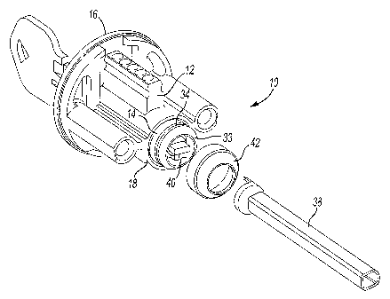
Referring to Figure 2, the core assembly 14 includes a barrel 30 and a
plug 32 (Figure 3). A keyway 22 (Figure 1 ) is defined in a front face 36 of
the
plug 32 to permit insertion of a key 24 such that the plug 32 can be rotated
to
operate the lock. Operation of the key to pin arrangement may take various
conventional forms and need not be described in detail herein.
For a deadbolt lock assembly, a torque blade 38 is received within a rear
segment 40 of the plug 32. The rear segment 40 defines a skirt 33 having a
circumferential groove 34 to receive fasteners 43 which extend from within a
frustum-conically shaped retainer 42 (Figure 4) to retain the torque blade 38
within the rear segment 40 (Figure 5). The skirt 33 preferably provides a
counter
bore to receive an end segment of the torque blade 38.
Referring to Figure 6, the plug 32 defines a longitudinal plug axis A. The
rear segment 40 defines a first plane P1 parallel to a second plane P2. The
planes P1, P2 are transverse and offset along the axis A (Figure 7). A first
engagement member 44 is located at least partially within the first plane P1
and
a second engagement member 46 is at least partially located within the second
plane P2. The first engagement member 44 is arranged generally perpendicular
to the second engagement member 46. The first and second engagement
member 44, 46 are preferably recessed within the skirt 33.
The first engagement member 44 is preferably a generally rectangular
shaped member 48, which extends from a circular member 50. The second
engagement member 46 includes the circular member 50 and a stop 52, which
extends from the radial periphery thereof. The circular member 50 defines an
inner diameter and the stop 52, which extends from the periphery of the
circular
member 50, defines an outer diameter.
Referring to Figure 8, the torque blade 38 is generally cylindrical. The
torque blade 38 preferably includes a female portion 52 and a rod portion 54.
The female portion 52 is preferably of a larger diameter than the rod portion
54.
The rod portion 54 typically engages an actuating plate (not shown) that
extends
-4-
CA 02557478 2006-08-24
WO 2005/086745 PCT/US2005/007277
through a latch bolt (not shown), which is conventional and need not be
described in detail herein. The female portion 52 includes a stepped section
56
(Figure 9).
In an assembled position, the female portion 54 is mounted over the
circular member 50 of the second engagement member 46. Rotation of the plug
32 within the barrel 30 rotates the second engagement member 46 into contact
with the stepped section 56 of the female portion to rotate the torque blade
38.
That is, the stop 52 is rotated into contact with stepped section 56 of the
female
portion 54, which is received at least partially over the circular portion 50
(Figure
10).
Referring to Figure 11, another lock housing 12' engages the core
assembly 14. That is, the core assembly 14 is universal and, in addition to
the
deadbolt housing discussed above, is engageable with a spindle assembly 60 for
a lever and knob. The core assembly 14 is typically mounted within a lever or
knob on one side of a door (not shown) and the spindle assembly 60 passes
through a door (not shown) to mount a knob or lever (not shown), which are
conventional and need not be described in detail herein.
Referring to Figure 12, the spindle assembly 60 is generally cylindrical.
The spindle assembly 60 preferably includes a female portion 62, which engages
the plug 32 and a rod portion 64, which mounts to the knob or lever opposite
the
knob or lever, which includes the core assembly 14.
The female portion 62 includes opposed spindle cams 66. The cams 66
are preferably axial partially triangular members, which extend toward axis A.
In an assembled position, the female portion 62 is mounted over the first
engagement member 44. The cams 66 which define a smaller diameter within
the female portion extend within an outer diameter defined by the first
engagement member 44. That is, the rectangular shaped member 48 is rotated
into contact with cams 66 of the female portion 62. Rotation of the plug 32
within
the barrel 30 rotates the first engagement member 44 into contact with the
cams
66 to rotate the spindle assembly 60 (Figure 13).
-5-
CA 02557478 2006-08-24
WO 2005/086745 PCT/US2005/007277
It should be understood that relative positional terms such as "forward,"
"aft," "upper," "lower," "above," "below," and the like are with reference to
the
normal operational attitude of the vehicle and should not be considered
otherwise limiting.
The foregoing description is exemplary rather than defined by the
limitations within. Many modifications and variations of the present invention
are
possible in light of the above teachings. The preferred embodiments of this
invention have been disclosed, however, one of ordinary skill in the art would
recognize that certain modifications would come within the scope of this
invention. It is, therefore, to be understood that within the scope of the
appended
claims, the invention may be practiced otherwise than as specifically
described.
For that reason the following claims should be studied to determine the true
scope and content of this invention.
-6-