Note: Descriptions are shown in the official language in which they were submitted.
CA 02558282 2006-08-31
RAMP KIT
[0001]
FIELD OF INVENTION
[0002] The present invention relates generally to ramps, and more
particularly, to ramp kits
of ramp components packaged in a disassembled condition for shipping and
storage.
BACKGROUND OF THE INVENTION
[0003] Numerous types of ramps are used to assist in the loading and unloading
of objects
from elevated positions, including transportation vehicles. Particularly,
trucks, vans, trailers
and the like utilize ramps to assist in the loading of objects such as ATVs,
motorcycles,
lawnmowers, etc. Due to the required length of these ramps, it is advantageous
that some
ramps are foldable so as to increase their use length and decrease their
storage length, while
other ramps may be one-piece units. One such foldable ramp is disclosed in
commonly
assigned U.S. Patent Application Serial No. 10/900,023, entitled Foldable Ramp
Having
Rung Hinge filed on July 27, 2004 (U.S. Publication No. 20050055783, published
March 17,
2005), and herein incorporated by reference herein.
[0004] Most ramps are typically manufactured from aluminum to promote a light
ramp with
overall strong properties. Therefore, a user can lift or unfold a ramp alone
when loading or
unloading a vehicle from a transportation vehicle. Further, these ramps are
often welded
together which increases the costs associated with manufacturing the ramps and
also requires
skilled personnel to operate the welding equipment. However, these ramps may
also be
riveted together. Again, such construction techniques require special rivet
fasteners that must
be installed by trained personnel. As such, the method of manufacture greatly
increases the
time and cost associated with producing such ramps.
[0005] Further, ramps manufactured by welding or riveting are shipped and sold
in their end-
use, constructed state, which makes transporting the ramps particularly
cumbersome and
expensive given their overall shape and length. And should a portion of the
ramp bend,
break, or be damaged during shipping or use, the ramp is often discarded in
its entirety or
attempted to be fixed in any unconventional manner.
CA 02558282 2006-08-31
SUMMARY OF THE INVENTION
[0006] The invention disclosed herein overcomes at least some of the
disadvantages
associated with the prior art by providing a ramp kit of ramp components
packaged in a
disassembled condition for ease of shipping and storage. Such a kit permits
the ramp to be
manufactured with replaceable parts and shipped disassembled so as to reduce
packaging and
shipping sizes. Also, such a construction permits the user to assembly the
ramp after
purchase and properly repair the ramp if required from available replacement
parts.
[0007] A ramp kit of ramp components packaged in a disassembled condition for
shipping
and storage generally comprising a plurality of elongated side members, a
plurality of cross
members having an integrally formed fastener engagement boss, and a plurality
of threaded
fasteners for connecting the cross members to the elongated side members to
assemble the
ramp. The ramp kit may also include a drive member for installing and removing
the
threaded fasteners as well as components being configured to be capable of
nesting along
their lengths to reduce the shipping size of the disassembled components.
[0008] The invention will be more fully described in the following written
description with
reference to the accompanying drawings.
BRIEF DESCRIPTION OF THE SEVERAL VIEWS OF THE DRAWING
[0009] FIG. 1 is a perspective, underside view of a foldable ramp in an
assembled state.
[0010] FIG. 1A is an exploded view of the ramp shown within circle A of FIG.
1.
[0011 ] FIG. 2 is view of the bottom section of the ramp of FIG. 1 showing the
hinge device.
[0012] FIG. 3 is a partially exploded view of the top section of the ramp of
FIG. 1.
[0013] FIG. 4 is a partially exploded view of the bottom section of the ramp
of FIG. 1.
[0014] FIG. 5 is a segmented view of the cross member of the ramp of FIG. 1
[0015] FIG. 6 is a segmented view of the end support member of the ramp of
FIG. 1.
DETAILED DESCRIPTION OF THE INVENTION
[0016] The ramp described herein is capable of being manufactured and shipped
in an
unassembled condition so as to keep the packaging and shipping sizes as small
as possible.
CA 02558282 2006-08-31
Therefore, the ramp is intended to be assembled by the customer, possibly with
tools supplied
with the ramp kit. Further, any damaged components can be removed or desired
changes the
configuration of the structure can be accomplished by user disassembly of the
ramp and
replacement of components. This is a distinct advantage over previously
constructed welded
and riveted ramps. And while the preferred embodiment of the invention is
directed to a
foldable vehicle ramp, it should be clear to anyone reading and understanding
this description
that the invention could be utilized for any type of ramp whether foldable or
otherwise and
that the following description of the preferred embodiment should in no way
limit the scope
of the invention or the claims as appended.
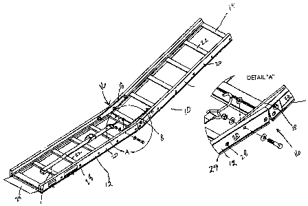
[0017] Referring now to the drawings, and in particular to FIG. 1, a ramp,
generally
designated 10, includes a first or upper ramp section 12 and a second or
bottom ramp section
14. The first and second ramp sections 12,14 are pivotally connected to each
other by a hinge
16. As shown in FIG. 1 A, the hinge 16 comprises a pair of brackets 18
connected to the inner
surface of the side members 20 of both the first and second ramp section
12,14. Each hinge
bracket 18 preferably comprises an A-shaped member having apertures
therethrough for
connecting to the first or second ramp members 12,14. For example, as best
shown in FIGS.
1A and 2, one side of the A-shaped bracket 18 is bolted to the second ramp
section 14 by a
two-bolt connection while the other end of the bracket 18 is pivotally
connected to the first
ramp section 12 or visa versa. Therefore, one of the ramp sections can pivot
relative to the
other ramp section so that the ramp 10 can be positioned between an extended,
operable
position shown in FIG. 1 and a folded, storage position (not shown).
[0018] The first ramp section 12 (shown in FIG. 3) and the second ramp section
14 (shown in
FIG. 4) are constructed having similar components, namely, a pair of elongated
side members
20, rungs or cross members 22, and an end support member 24. Side members 20
comprise
elongated tubular members having a longitudinal channel 26 located on an inner
surface
thereof. The end support member 24 and the cross members 22 each have
predetermined
lengths, first and second ends, and a fastener engagement boss 36 integrally
formed therein.
The ends of end support member 24 and cross members 22 are capable of nesting
within the
CA 02558282 2006-08-31
longitudinal channels 26 of the side members 20 and being connected thereto
through
mounting apertures 28.
[0019] As best shown in FIG. S, the cross member 22 comprises an elongated
tubular
member having a support surface 30, a pair of side walls 32, a base 34, and a
bolt engaging
boss 36 (a C-shaped channel at a central portion thereof for receiving a self
tapping screw).
Preferably, the elongated members 20, the cross members 22, and the end
support members
24 are each integrally formed from a light-weight material, preferably
extruded aluminum,
while any other suitable materials can be used. The end support member 24, as
best shown in
FIG. 6, comprises a box-shaped base 40 having a fastener engaging boss 36
therethrough and
an inclined surface 44 extending therefrom. All of the components of the ramp
10 are
preferably manufactured from aluminum so as to provide a lightweight component
having a
high strength level.
[0020] The ramp 10 is constructed wherein self tapping screws 46 are inserted
through the
mounting apertures 28 of the side members 20 and engage the fastener engaging
bosses 36
formed in the cross members 22 and end support member 24. Each cross member 22
and end
support member 24 has screw bosses 36 formed during the aluminum extrusion
process. The
'/-20x3/4 zinc plated steel torx pan head type F screws 46 are self tapped
into the bosses 36
using a hand tool or power tool bit which could be supplied in the ramp kit.
The side
members 20 are tightened to the cross members 22 and to the end support member
24 to form
the upper ramp section 12 and lower ramp section 14. Such a novel construction
permits ease
of assembly and disassembly so that the ramp 10 can be shipped disassembled to
the
customer for assembly, thus saving packaging and shipping space, as well as
permitting the
removal and replacement of damaged components. The screw design permits the
ramp to flex
under heavy loads with no weld stress points so the ramp can achieve a higher
load rating (no
welding failure).
[0021 ] As indicated above, the particular ramp design and construction
enables the
components to be prefabricated and packaged in a disassembled condition for
shipping and
storage in a ramp kit and assembled by the end user. Due to the disassembled
construction
4
CA 02558282 2006-08-31
and the nestable configuration of the ramp components, the ramp kit takes up
substantially
less shipping and storage space as opposed to the previously welded or riveted
ramp
constructions.
[0022] As such, a ramp kit of ramp components packaged in a disassembled
condition for
shipping and storage generally comprises a plurality of elongated side members
20, a
plurality of cross members 22, and a plurality of threaded fasteners 42 for
connecting the
components. It is likely that the ramp kit would also include a tool as part
of the ramp kit to
enable the user to assemble and disassemble the ramp. However, depending upon
the type of
fasteners used, the ramp kit may not include a tool in that the user may be
able to use a
simple wrench or screwdriver to assemble the ramp.
[0023] The elongated side members 20 each have a predetermined length and a
longitudinal
channel 26 along their lengths. Any number of side members 20 can be provided
having any
number of predetermined lengths. As indicated below, due to ramp sections
constructed with
pairs of side members, it is preferable that there be at least two side
members of similar
length. At least one mounting aperture 28 is provided in the side members to
connect the side
members 20 to the cross members 22 and end support member 24. Preferably, the
mounting
apertures 28 are located systematically along the side member 20 to provide
proper spacing
for the cross members 22. Further, additional mounting apertures 28 may be
provided so that
additional cross member configurations can be achieved as desired. 16. The
side member 20
also includes an upwardly extending side structure 29 extending along its
length to provide a
wall to prevent the accidental movement of an object off of the surface of the
ramp.
[0024] The cross members 22 also have a predetermined length and a first and
second end.
Again, any number of side members 20 can be provided having any number of
predetermined
lengths. A fastener engagement boss 36 is integrally formed within the cross
member
wherein the ends are capable of insertion within the corresponding
longitudinal channels 26
of a pair of side members 20 so that the fastener engagement bosses 26 align
between
corresponding mounting apertures 28.
CA 02558282 2006-08-31
[0025] The threaded fasteners 42 are each capable of insertion within the
mounting apertures
28 of the side members 20 and engagable with the fastener engagement bosses of
the cross
members 22 and end support members 24. Any kind of threaded fastener can be
utilized
having any type of drive means, including Phillips, Standard, Hex-head, star-
shaped, or any
other know driving surface configuration. If a tool in included with the ramp
kit, it would be
required to engage the driving surface as provided.
[0026] The ramp kit and therefore the ramp 10 may or may not include at least
one end
support member 24. The end support members 24 are of a predetermined length
having first
and second mounting ends. A fastener engagement boss 36 is integrally formed
within the
first and second mounting ends so that the fastener engagement bosses 36 align
with the
mounting apertures 28 or the side members 20. Therefore, the ends of the
support members
24 are capable of insertion within the corresponding longitudinal channels 26
of a pair of side
members 20 and fastened thereto to assemble the ramp. 13. As shown in FIG. 6,
the end
support member 24 preferably includes a lip portion 44 extending along at
least a portion of
the length of the body 40 and extending outwardly therefrom at a predetermined
angle.
[0027] Preferably, the ramp kit provides the assembly of a ramp having
pivotable upper and
lower ramp sections. As described above, an upper ramp section 12 comprises a
first pair of
side members 20, a plurality of cross members 22. At least one support member
24 may also
be utilized to form the upper ramp section 12. A second pair of side members
20 and a
plurality of cross members 22 form a lower ramp section 14. A hinge device 16
joins the
upper ramp section 12 and the lower ramp section 14 to create a pivotable ramp
sp that the
ramp sections 12,14 are pivotable between an extended, working position and a
collapsed,
storage position.
[0028] Of significant importance related to the reduced shipping size of the
ramp kit, the
components are configured to provide nesting during packaging and shipment.
Particularly,
the longitudinal channel 26 of the side members 20 and the cross members 22
and end
support members 24 are configured such that the cross members 22 and the end
support
members 24 are capable of nesting along their lengths within the longitudinal
channel 26
CA 02558282 2006-08-31
during packaging and shipment. Therefore, as the packaging size of the ramp is
greatly
reduced by provide a disassembled ramp kit, the packing size if further
reduced by
configuring several components to nest together thereby additionally reducing
packaging
space.
[0029] The invention has been described with reference to the preferred
embodiment.
Obviously, modifications and alternations will occur to others upon a reading
and
understanding of this specification. The claim as follows is intended to
include all
modifications and alterations insofar as they come within the scope of the
claim or an
equivalent thereof.
7