Language selection

Search

Patent 2558308 Summary

Third-party information liability

Some of the information on this Web page has been provided by external sources. The Government of Canada is not responsible for the accuracy, reliability or currency of the information supplied by external sources. Users wishing to rely upon this information should consult directly with the source of the information. Content provided by external sources is not subject to official languages, privacy and accessibility requirements.

Claims and Abstract availability

Any discrepancies in the text and image of the Claims and Abstract are due to differing posting times. Text of the Claims and Abstract are posted:

  • At the time the application is open to public inspection;
  • At the time of issue of the patent (grant).
(12) Patent: (11) CA 2558308
(54) English Title: METHOD AND APPARATUS FOR CHARACTERISING A THREE PHASE TRANSFORMER USING A SINGLE PHASE POWER SUPPLY
(54) French Title: PROCEDE ET APPAREIL PERMETTANT DE CARACTERISER UN TRANSFORMATEUR TRIPHASE AU MOYEN D'UNE ALIMENTATION MONOPHASEE
Status: Expired and beyond the Period of Reversal
Bibliographic Data
(51) International Patent Classification (IPC):
(72) Inventors :
  • FAWCETT, TIMOTHY JAMES (United Kingdom)
(73) Owners :
  • HAEFELY TEST, AG
(71) Applicants :
  • HAEFELY TEST, AG (Switzerland)
(74) Agent: MOFFAT & CO.
(74) Associate agent:
(45) Issued: 2012-01-31
(86) PCT Filing Date: 2005-03-03
(87) Open to Public Inspection: 2005-09-15
Examination requested: 2006-09-01
Availability of licence: N/A
Dedicated to the Public: N/A
(25) Language of filing: English

Patent Cooperation Treaty (PCT): Yes
(86) PCT Filing Number: PCT/GB2005/000810
(87) International Publication Number: GB2005000810
(85) National Entry: 2006-09-01

(30) Application Priority Data:
Application No. Country/Territory Date
0404918.5 (United Kingdom) 2004-03-04

Abstracts

English Abstract


A method and apparatus for characterising a three phase transformer (3) using
a single phase power supply (1). Pairs of input terminals (H0-H3) of the
transformer are sequentially energised for each energisation and the voltage
between pairs of output terminals (x0-x3) of the transformer are measured.
Measured voltages are processed in order to characterise the winding
configuration of the transformer. Either simultaneously or subsequently the
presence of neutrals on the primary and/or secondary side of the transformer
are identified to enable the winding configuration to be further
characterised. Subsequently any phase displacement of the transformer is
determined. The apparatus comprises means (2) for selectively applying a
single phase power supply (1) to pairs of terminals (H0-H3) on the transformer
(3) and for measuring voltages between pairs of terminals (x0-x3) of the
transformer and for measuring phase difference between the primary and
secondary sides of the transformer all under automatic control of a control
means (13) which includes a processing means to process measured voltages and
phase differences in order to characterise the transformer.


French Abstract

L'invention concerne un procédé et un appareil qui permettent de caractériser un transformateur triphasé (3) au moyen d'un alimentation monophasée (1). Des paires de bornes d'entrée (H0-H3) du transformateur sont séquentiellement mises sous tension pour chaque mise sous tension et la tension entre les paires de bornes de sortie (x0-x3) du transformateur sont mesurées. Les tensions mesurées sont traitées afin de caractériser la configuration d'enroulement du transformateur. La présence de conducteurs neutres sur le côté primaire et/ou le côté secondaire du transformateur est identifiée, soit simultanément, soit séquentiellement, de façon à caractériser davantage la configuration d'enroulement. Par la suite, n'importe quelle déphasage du transformateur est déterminé. L'appareil comprend un moyen (2) permettant d'appliquer sélectivement une alimentation monophasée (1) sur des paires de bornes (H0-H3) figurant sur le transformateur (3), de mesurer les tensions entre les paires de bornes (x0-x3) du transformateur et de mesurer la différence de phase entre le côté primaire et le côté secondaire du transformateur, le tout sous le contrôle automatique d'un moyen de contrôle (13) qui comprend un moyen permettant de traiter les tensions mesurées et les différences de phase afin de caractériser le transformateur.

Claims

Note: Claims are shown in the official language in which they were submitted.


CLAIMS
1. A method of characterising a three phase transformer having three input
terminals and three output terminals using a single phase power supply, the
method comprising the steps of:
sequentially connecting the single phase power supply between all three
available pairs of input terminals selected from the three input terminals of
the
transformer so as to energise each available pair of input terminals in turn;
during energisation of each pair of terminals measuring the voltage
between all three available pairs of output terminals selected from the three
output terminals of the transformer; and
processing the measured voltages to characterise the transformer
according to its winding configuration.
2. A method as claimed in claim 1 wherein the transformer is classified as D-
D equivalent, D-Y equivalent, Y-D equivalent or Y-Y equivalent.
3. A method as claimed in claim 2 wherein the three voltages measured
during energisation of each pair of input terminals are processed to identify
the
highest, lowest and intermediate value and the difference between the
intermediate value less the lowest value computed and then divided by the
highest value to produce three figures of merit, one associated with
energisation
of each pair of input terminals.
4. A method as claimed in claim 3 wherein each figure of merit is classified
into one of four classes according to its value.
5. A method as claimed in claim 4 wherein each figure of merit is classified
in
a first class if it is greater than 0.82, a second class if it is less than or
equal to
22

0.82 but greater than 0.45, a third class if it is less than or equal to 0.45
but
greater than 0.16 and a fourth class if it is less than or equal to 0.16.
6. A method as claimed in either claim 4 or 5 wherein a value is allocated to
each figure of merit according to its classification, the allocated values are
then
added, and the transformer classified as D-D equivalent, D-Y equivalent, Y-D
equivalent or Y-Y equivalent according to the total.
7. A method as claimed in claim 6 wherein the first, second, third and fourth
classes are allocated the decimal numbers 64, 16, 4 and 1 respectively, or
equivalent numbers in a different base, and the transformer classified as
follows
according to the total of the allocated values:
Winding Classification Sum of Values
D-D 33
D-Y 72
Y-D 96
Y-Y 9
8. A method as claimed in any one of claims 2 to 7, wherein the transformer
is characterised according to the presence of neutrals on its primary side,
secondary side, or both primary and secondary sides.
9. A method as claimed in claim 8 wherein the transformer has three input
terminals H1, H2 and H3 and an input neutral terminal HO and three output
terminals X1, X2 and X3 and an output neutral XO and when the single phase
power supply is connected between input terminals H1 and H3 the highest
voltage measured between output terminals X1 and X3, X2 and X1 and X3 and
X2, referred to herein as `X pp`, is saved and the highest voltage measured
between X1 and XO, X2 and XO and X3 and XO, referred to herein as `X pn`, is
23

saved and further comprising the step of connecting the single phase power
supply between H1 and HO, measuring the voltages between X1 and X3, X2 and
X1, and X3 and X2, saving the highest value, referred to herein as 'X np', and
determining the ratios of the first saved voltage with each of the second and
third
saved voltages respectively, said ratios being X pn/X pp and X np/X pp,
thereby to
determine the presence of neutrals on the primary side, secondary side or both
primary and secondary sides of the transformer.
10. A method as claimed in claim 9 wherein the presence or absence of a
neutrals is combined with the classification of winding configuration in order
to
further classify the winding configuration of the transformer as one of the
following:
a) D-D or D-Z or Z-D or Z-Z
b) D-Z n
c) Z n-D or Z n-Z
d) Z n-Z n
e) D-Y or Z-Y
f) D-Y n or Z-Y n
g) Z n-Y
h) Z n-Y n
i) Y-D or Y-Z
j) Y-Z n
k) Y n-D or Y n-Z
i) Y n-Z n
m) Y-Y
n) Y-Y n
0) Y n-Y
p) Y n-Y n
24

11. A method as claimed in any one of claims 2 to 10, wherein the phase
displacement of the transformer is calculated by the following steps:
determining if the primary and secondary winding configurations are
similar and if not allocating a value of I, otherwise allocating a value of 0;
determining a configuration result factor and adding a value according to
the configuration result factor to the value allocated in the previous step;
determining if the secondary winding of the transformer windings is
reversed and if not adding 6 to the value calculated in the previous step,
otherwise leaving the value unaltered; and
if the value is greater than 12 subtracting 12, otherwise leaving the value
unaltered, thereby to determine the phase displacement of the transformer.
12. A method as claimed in claim 11 wherein the configuration result factor is
determined as follows:
during energisation of each pair of input terminals shorting the remaining
terminal to the low end of the energising power supply noting the pair of
output
terminals across which the lowest output is measured and allocating a value
depending on at which pair of output terminals the lowest output is measured,
said value also depending upon whether or not the primary and secondary
winding configurations are similar or not and naming the three values
allocated to
obtain the configuration result factor.
13. A method according to either claim 11 or 12 wherein to determine if the
secondary windings of the transformer are reversed the transformer is
energised
phase to phase on the primary and a corresponding phase to phase
measurement made on the secondary and measuring the phase shift and the
primary with respect to the secondary.
14. A method as claimed in claim 1, wherein the three voltages measured
during energisation of each pair of input terminals are processed to identify
the
highest, lowest and intermediate value and the difference between the

intermediate value less the lowest value computed and then divided by the
highest value to produce three figures of merit, one associated with
energisation
of each pair of input terminals.
15. A method as claimed in claim 14 wherein each figure of merit is classified
into one of four classes according to its value.
16. A method as claimed in claim 15 wherein each figure of merit is classified
in a
first class if it is greater than 0.82, a second class if it is less than or
equal to 0.82
but greater than 0.45, a third class if it is less than or equal to 0.45 but
greater
than 0.16 and a fourth class if it is less than or equal to 0.16.
17. A method as claimed in either claim 15 or 16 wherein a value is allocated
to each figure of merit according to its classification, the allocated values
are then
added, and the transformer classified as D-D equivalent, D-Y equivalent, Y-D
equivalent or Y-Y equivalent according to the total.
18. A method as claimed in claim 17 wherein the first, second, third and
fourth
classes are allocated the decimal numbers 64, 16, 4 and 1 respectively, or
equivalent numbers in a different base, and the transformer classified as
follows
according to the total of the allocated values:
Winding Classification Sum of Values
D-D 33
D-Y 72
Y-D 96
Y-Y 9
26

19. A method as claimed in any one of claims 14 to 20, wherein the
transformer is characterised according to the presence of neutrals on its
primary
side, secondary side or both primary and secondary sides.
20. A method as claimed in claim 8 wherein the transformer has three input
terminals H1, H2 and H3 and an input neutral terminal HO and three output
terminals X1, X2 and X3 and an output neutral XO and when the single phase
power supply is connected between input terminals H1 and H3 the highest
voltage measured between output terminals X1 and X3, X2 and X1 and X3 and
X2, referred to herein as `X pp', is saved and the highest voltage measured
between X1 and XO, X2 and XO and X3 and XO, referred to herein as 'X pn', is
saved and further comprising the step of connecting the single phase power
supply between H1 and HO, measuring the voltages between X1 and X3, X2 and
X1, and X3 and X2, saving the highest value, referred to herein as 'XnP', and
determining the ratios of the first saved voltage with each of the second and
third
saved voltages respectively, the ratios beingX pn/X pp and X np,X pp, thereby
to
determine the presence of neutrals on the primary and/or secondary side of the
transformer.
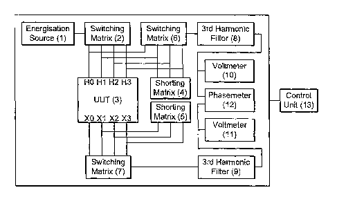
21. An apparatus comprising:
a three phase transformer having three input terminals and three output
terminals;
a single phase power supply;
means for sequentially connecting the single phase power supply between
all three available pairs of input terminals selected from the three input
terminals
of the transformer so as to energise each available pair of input terminals in
turn;
means for measuring the voltage between all three available pairs of
output terminals selected from the three output terminals of the transformer
during energisation of each pair of terminals; and
means for processing the measured voltages to characterise the
transformer according to its winding configuration.
27

22. An apparatus as claimed in claim 21 wherein the means for processing is
arranged to classify the transformer as D-D equivalent, D-Y equivalent, Y-D
equivalent or Y-Y equivalent.
23. An apparatus as claimed in claim 21 or claim 22, wherein the means for
processing is further arranged to identify the highest, lowest and
intermediate
value and the difference between the intermediate value less the lowest value
computed and then divided by the highest value to produce three figures of
merit,
one associated with energisation of each pair of input terminals.
24. An apparatus as claimed in claim 23 wherein the means for processing is
further arranged to classify each figure of merit into one of four classes
according
to its value.
25. An apparatus as claimed in claim 24 wherein the means for processing is
further arranged to classify each figure of merit in a first class if it is
greater than
0.82, a second class if it is less than or equal to 0.82 but greater than
0.45, a
third class if it is less than or equal to 0.45 but greater than 0.16 and a
fourth
class if it is less than or equal to 0.16.
26. An apparatus method as claimed in either claim 24 or 25 wherein the
means for processing is further arranged to allocate a value to each figure of
merit according to its classification, and then add the allocated values ,
means for
processing being arranged to classify the transformer as D-D equivalent, D-Y
equivalent, Y-D equivalent or Y-Y equivalent according to the total.
27. An apparatus as claimed in claim 26 wherein the means for processing is
further arranged to allocate the first, second, third and fourth classes the
decimal
28

numbers 64, 16, 4 and 1 respectively, or equivalent numbers in a different
base,
the transformer being classified as follows according to the total of the
allocated
values:
Winding Classification Sum of Values
D-D 33
D-Y 72
Y-D 96
Y-Y 9
28. An apparatus as claimed in any one of claims 21 to 27, wherein the
transformer is characterised according to the presence of neutrals on its
primary
side secondary side, or both primary and secondary sides.
29. An apparatus as claimed in claim 28 wherein the transformer has three
input terminals H1, H2 and H3 and an input neutral terminal HO and three
output
terminals X1 , X2 and X3 and an output neutral XO and when the single phase
power supply is connected between input terminals H1 and H3, the means for
processing being arranged to save the highest voltage measured between output
terminals X1 and X3, X2 and X1 and X3 and X2, referred to herein as 'X pp',
and
to save the highest voltage measured between X1 and XO, X2 and XO and X3
and XO, referred to herein as 'X pn', the means for processing being further
arranged to connect the single phase power supply between H1 and HO,
measure the voltages between X1 and X3, X2 and X1 , and X3 and X2, save the
highest value, referred to herein as 'X np' and determine the ratios of the
first
saved voltage with each of the second and third saved voltages respectively,
the
ratios being X pn/X pp and X np/X pp, thereby to determine the presence of
neutrals on
29

the primary side, secondary side or both primary and secondary sides of the
transformer.
30. An apparatus as claimed in claim 29 wherein the means for processing is
further arranged to combine the presence or absence of a neutrals with the
classification of winding configuration in order to further classify the
winding
configuration of the transformer as one of the following:
a) D-D or D-Z or Z-D or Z-Z
b) D-Zn
c) Zn-D or Zn-Z
d) Zn-Zn
e) D-Y or Z-Y
f) D-Yn or Z-Y,
g) Zn-Y
h) Zn-Yn
i) Y-D or Y-Z
j) Y-Zn
k) Yn-D or Yn-Z
l) Yn-Zn
m) Y-Y
n) Y-Yn
0) Yn-Y
p) Yn-Yn
31. An apparatus as claimed in any one of claims 22 to 30, wherein the
means for processing is further arranged to calculate the phase displacement
of
the transformer by having:

means for determining if the primary and secondary winding
configurations are similar and if not allocating a value of 1, otherwise
allocating a
value of 0;
means for determining a configuration result factor and adding a value
according to the configuration result factor to the value allocated in the
previous
step;
means for determining if the secondary winding of the transformer
windings is reversed and if not adding 6 to the value calculated in the
previous
step, otherwise leaving the value unaltered; and
if the value is greater than 12 means for subtracting 12, otherwise leaving
the value unaltered, thereby to determine the phase displacement of the
transformer.
32. An apparatus as claimed in claim 31 wherein the means for determining a
configuration result factor is arranged to:
during energisation of each pair of input terminals, short the remaining
terminal to the low end of the energising power supply noting the pair of
output
terminals across which the lowest output is measured and allocating a value
depending on at which pair of output terminals the lowest output is measured,
said value also depending upon whether or not the primary and secondary
winding configurations are similar or not and naming the three values
allocated to
obtain the configuration result factor.
33. An apparatus according to either claim 31 or 32 wherein the means to
determine if the secondary windings of the transformer are reversed is
arranged
to determine when the transformer is energised phase to phase on the primary
and a corresponding phase to phase measurement made on the secondary and
measuring the phase shift and the primary with respect to the secondary.
34. An apparatus as claimed in claim 21, wherein the means for processing is
further arranged to identify the highest, lowest and intermediate value and
the
31

difference between the intermediate value less the lowest value computed of
the
three voltages measured during energisation of each pair of input terminals,
the
means for processing further arranged to then divide by the highest value to
produce three figures of merit, one associated with energisation of each pair
of
input terminals.
35. An apparatus as claimed in claim 34 wherein the means for processing is
further arranged to classify each figure of merit into one of four classes
according
to its value.
36. An apparatus as claimed in claim 35 wherein the means for processing is
further arranged to classify each figure of meritin a first class if it is
greater than
0.82, a second class if it is less than or equal to 0.82 but greater than
0.45, a
third class if it is less than or equal to 0.45 but greater than 0.16 and a
fourth
class if it is less than or equal to 0.16.
37. An apparatus as claimed in either claim 34 or 35 wherein the means for
processing is further arranged to allocate a value to each figure of merit
according to its classification, the allocated values being added, and the
means
for processing is being arranged to classify the transformer as D-D
equivalent, D-
Y equivalent, Y-D equivalent or Y-Y equivalent according to the total.
38. An apparatus as claimed in claim 37 wherein the means for processing is
further arranged to allocate the first, second, third and fourth classes the
decimal
numbers 64, 16, 4 and 1 respectively, or equivalent numbers in a different
base,
and the means for processing being arranged to classify the transformer as
follows according to the total of the allocated values:
Winding Classification Sum of Values
D-D 33
32

D-Y 72
Y-D 96
Y-Y 9
39. The apparatus as claimed in any one of claims 34 to 38, wherein the
transformer is characterised according to the presence of neutrals on its
primary
side, secondary side or both primary and secondary sides.
40. An apparatus as claimed in claim 39 wherein the transformer has three
input terminals H1, H2 and H3 and an input neutral terminal HO and three
output
terminals X1, X2 and X3 and an output neutral XO and when the single phase
power supply is connected between input terminals H1 and H3, the means for
processing is further arranged to save the highest voltage measured between
output terminals X1 and X3, X2 and X1 and X3 and X2, referred to herein as `
X pp',and save the highest voltage measured between X1 and XO, X2 and XO and
X3 and XO, referred to herein as 'X pn', and the means for processing is
further
arranged to connect the single phase power supply between H1 and HO,
measure the voltages between X1 and X3, X2 and X1, and X3 and X2, save the
highest value, referred to herein as 'X np', and determine the ratios of the
first
saved voltage with each of the second and third saved voltages respectively,
the
ratios being X pn/X pp and X np,X pp, thereby to determine the presence of
neutrals on
the primary and/or secondary side of the transformer.
41. An apparatus as claimed in any one of claims 21 to 40, further comprising:
means for selectively applying power from the power supply to the pairs of
input terminals of the three phase transformer;
means for measuring the voltage between pairs of output terminals of the
three phase transformer and a control means comprising a processing means,
said control means being operative to control the power supply,
means for measuring voltages; and
processing means thereby to characterise a three phase transformer.
33

42. An apparatus as claimed in claim 41, further comprising a phase meter
under control of the control means.
43. An apparatus as claimed in either claim 41 or 42 wherein the control
means comprises a programmed computer.
34

Description

Note: Descriptions are shown in the official language in which they were submitted.


CA 02558308 2006-09-O1
WO 2005/085885 PCT/GB2005/000810
1
METHOD AND APPARATUS FOR CHARACTERISING A THREE PHASE
TRANSFORMER USING A SINGLE PHASE POWER SUPPLY
The present invention relates to a method and apparatus for characterising a
three phase transformer using a single phase power supply.
Three phase transformers are widely used in power supply and other
applications. They typically comprise primary and secondary windings for each
phase mounted on a three legged core.
The turns ratio of a transforiner is the ratio of the number of turns of its
primary winding divided by the number of turns of the secondary winding, for
each
leg of the transformer. The turns ratio is equivalent to the step up or step
down
voltage ratio of the transformer. By measuring the turns ratio of a
transformer from
its performance and comparing this with its rated voltage a good indication of
the
condition of the transformer can be obtained.
Transformers are routinely tested in this way throughout their life. Typically
testing is carned out after manufacture to ensure that the transformer has
been
correctly wound, similarly after refurbishment or remanufacture, and as part
of
ongoing maintenance in order to detect any degradation in performance.
Probably the simplest way to measure the turns ratio of a three phase
transformer, at least from the point of view of the apparatus required, is to
use a single
phase power supply to test the three pairs of primary and secondary windings
individually. This approach is particularly desirable for field testing where
providing
a single phase power supply for testing is easier than providing a three phase
supply.
In fact provision of an appropriate three phase power supply may be
impossible.
A drawback with use of a single phase supply to measure the turns ratio of a

CA 02558308 2006-09-O1
WO 2005/085885 PCT/GB2005/000810
2
three phase transformer is that the way voltage should be applied to the
transformer
and the way it should be measured depends on characteristics of the
transformer being
tested, particularly its configuration and phase displacement, if any
The primary and secondary windings of a three phase transformer can each be
connected in one of five known configurations D (Delta), Y (Wye), Yn, Z (Zig
Zag)
and Zn.
In D configuration three windings are connected end to end in a loop and three
external connections for the transformer are taken from between the windings.
In Y
configuration (also known as star configuration) one end of each winding are
all
connected together. The free ends of each winding form three external
connections.
In Yn configuration the connection between the three windings of a Y
configuration is
brought out as an additional neutral connection. Z configuration is
electrically the
same as Y, but each winding is distributed across more than one leg of the
transformer
to improve performance in the presence of an unbalanced load. Zn is a Z
1 S configuration with the connection between the windings brought out as
neutral.
A three phase transformer can have a phase displacement. Shifting the
secondary connections with respect to the primary connections, essentially re-
labelling the connections, introduces a phase shift in 60 degree steps, as can
reversing
the windings. Configuration of the windings also affects phase. If
configurations of
the primary and second side are dissimilar an additional 30 degree shift is
introduced.
Phase displacement is usually classified using a number between 0 and 11 to
indicate
the number of 30 degree steps from in phase introduced by the transformer.
Before the turns ratio of a transformer can be properly measured using a
single

CA 02558308 2006-09-O1
WO 2005/085885 PCT/GB2005/000810
3
phase power supply it is necessary to know the winding configuration and any
phase
displacement of the transformer.
It is an object of the present invention to enable the windings configuration
and/or phase displacement of a three phase transformer to be determined using
a
single phase power supply. It is a particular object to enable winding
configuration
and/or phase displacement to be automatically determined.
According to a first aspect of the present invention, there is provided a
method
of characterising a three phase transformer having three input terminals and
three
output terminals using a single phase power supply, the method comprising the
steps
of
sequentially connecting the single phase power supply between all three
available pairs of input terminals selected from the three input terminals of
the
transformer so as to energise each available pair of input terminals in turn;
during energisation of each pair of terminals measuring the voltage between
all three available pairs of output terminals selected from the three output
terminals of
the transformer; and
processing the measured voltages to characterise the transformer.
According to a second aspect of the present invention, there is provided
apparatus for characterising a three phase transformer using the method of the
first
aspect of the present invention.
When characteristics of the transformer have been determined, it is possible
for the turns ratio of the transformer to be measured using a single phase
power
supply.

CA 02558308 2006-09-O1
WO 2005/085885 PCT/GB2005/000810
4
Preferably, the method and apparatus enable a three phase transformer to be
characterised according to its winding configuration. The method and apparatus
may
classify a three phase transformer as either D-D equivalent, D-Y equivalent, Y-
D
equivalent or Y-Y equivalent. The method and apparatus may further classify a
S transformer according to the presence of a neutral on either the primary or
secondary
side of the transformer, thereby to further characterise its winding
configuration.
The method and apparatus also preferably enables the phase displacement of a
transformer to be characterised.
The apparatus preferably comprises a single phase power supply and means
for selectively applying power from the power supply to pairs of input
terminals of a
three phase transformer. Said means may comprise a switching matrix. The
apparatus preferably further comprises means for measuring voltage between
pairs of
output terminals of a three phase transformer, which means may also include a
switching matrix. The apparatus may further include a phase meter. The various
components of the apparatus are preferably under the control of a control
means
which may comprise a programmed computer. The control means preferably
includes a processing means for processing measured voltages in order to
determine
characteristics of the transformer. The apparatus may further include means
for
shorting any two terminals of a transformer together. Such means may comprise
a
shorting matrix.
The apparatus is preferably arranged to automatically characterise a
transformer and provide results to a user. The apparatus may be further
arranged to
automatically test the turns ratio of a transformer using the single phase
power supply,

CA 02558308 2006-09-O1
WD 2005/085885 PCT/GB2005/000810
by the application of a known method.
The apparatus is preferably self contained and portable to facilitate in the
field
testing of transformers. The power supply of the apparatus may be provided by
a local
mains power supply.
S In order that the invention may be more clearly understood an embodiment
thereof will now be described, by way of example, with reference to the
accompanying drawings of which:
Figure 1 is a schematic diagram of apparatus according to the invention;
Figure 2 is a flowchart illustrating operation of the apparatus of Figure 1;
and
Figure 3 is another flowchart illustrating further operation of the apparatus
of
Figure 1.
An embodiment of the invention will be described with reference to a notional
three phase transformer to be tested having input (primary) terminals H1, H2,
H3 and
optionally an input neutral terminal H0, and output (secondary) terminals X1,
X2, X3
and optionally an output neutral terminal X0.
First the winding configuration of a transformer to be tested is determined.
Because the primary and secondary windings of a three phase transformer can
each be wound in five ways there are a total of twenty five possible
configurations for
a transformer, as set out below, however it is unlikely to find all these
configurations
in practice.
D-D D-Y D-Yn D-Z D-Zn
Y-D Y-Y Y-Yn Y-Z Y-Zn
Yn-D Yn-Y Yn- Yn-Z Yn-
Yn Zn

CA 02558308 2006-09-O1
WO 2005/085885 PCT/GB2005/000810
6
Z-D Z-Y Z-Yn Z-Z Z-Zn
Zn-D Zn-Y Zn- Zn-Z Zn-
Zn Zn
Single-phase energisation of a transformer with a Z configuration produces the
same results as a D configuration, so it is impossible to distinguish between
the two.
The use of Z windings on the primary of a transformer is unusual so these are
treated
as a special case. Because of the equivalent behaviour of Z and D windings,
they are
defined as similar, with Y windings being treated as different. This gives two
groups
of winding configurations:
D - Z - Zn; and
Y - Yn
This allows transformers to be grouped into four groups depending on the
configuration of their primary and secondary windings, as set out below.
Group D-D D-D, D-Z, D-Zn, Z-D, Z-Z,
Z-Zn,
1 equivalentZn-D, Zn-Z, Zn-Zn
Group D-Y D-Y, D-Yn, Z-Y, Z-Yn, Zn-Y,
Zn-
2 equivalentYn
Group Y-D Y-D, Y-Z, Y-Zn, Yn-D, Yn-Z,
Yn-
3 equivalentZn
Group Y-Y Y-Y, Y-Yn, Yn-Y, Yn-Yn
4 equivalent
Energising a transformer input to input on the primary side and measuring the
output to output voltages obtained on the secondary side allows a
discrimination of
the transformer's class to be made. The transformer is energised H1-H3, H2-H1
and

CA 02558308 2006-09-O1
WD 2005/085885 PCT/GB2005/000810
7
H3-H2 and with each energisation the line-to-line voltages Xl-X3, X2-X1 and X3-
X2
are measured. Each set of three secondary measurements is normalised to the
highest
line-to-line voltage measured for that energisation. The theoretical results
expected for
transformers of each group identified above are as follows:
Ener ise Measure Groun Group Groun Groun
1 2 3 4
(D-DIDI D~-Y ~Y-D) (Y-~
X1-X3 1 0.666 1 1
H1-H3 X2-X1 0.85 1 0 0.5
X3-X2 0.15 0.333 1 0.5
X1-X3 0.5 0 0.85 0.333
H2-H 1 X2-X 1 1 1 1
1
X3-X2 0.5 1 0.15 0.666
X1-X3 0.15 0.666 0.15 0.333
H3-H2 X2-X1 0.85 0.333 1 0.666
X3-X2 1 1 0.85 1
This shows that four response patterns can be expected to be observed, which
can be
classified as follows:
Class Response
A 1:1:0
B 1:0.85:0.15
C 1:0.66:0.33
D 1:0.5:0.5
The responses of the four groups of transformers can be further classified
according to
the classes of response that they show thus:
Group 1 (D-D) _ (2 * Class B) + (1 * Class D)
Group 2 (D-~') _ (2 * Class C) + (1 * Class A)

CA 02558308 2006-09-O1
WO 2005/085885 PCT/GB2005/000810
Group 3 (Y-D) _ (2 * Class B) + ( 1 * Class A)
Group 4 (Y-Y) _ (2 * Class C) + (1 * Class D)
So, by determining the class of response under each of the possible line-to-
line
energisations, it is possible to determine the group of the transformer under
test. The
expected voltage values shown above are theoretical ideal values and may not
be seen
in practice. Therefore to classify transformers in practice a range of values
is
substituted for each expected value and measured voltages are classified
according to
the range in which they fall.
Once the class of the transformer has been determined, it is necessary to
determine if it has neutral connections. If there is no neutral connection,
there is
essentially a floating connection. The presence of a primary neutral can be
determined by comparing the voltage produced on the secondary measuring output
to
output when the primary is energised input to input and input to neutral. If
there is a
significant difference recorded it indicates that the neutral line is floating
(i.e. not
connected). A similar process can be followed to determine the presence of a
neutral
on the secondary side. The transformer is energised input to input on the
primary and
the output to output and output to neutral voltages on the secondary are
compared.
Again if there is a significant difference, it indicates that the neutral line
is floating
(i.e. not connected).
When the group of transformer and the presence or absence of primary and
secondary neutral connections is known, it is possible to determine the
winding
configuration:
Transformer: Prfm. Sec Type

CA 02558308 2006-09-O1
WO 2005/085885 PCT/GB2005/000810
9
Neut. Neut.
No No D-D (or
D-Z
or Z-D or
Z-
Z)
Group 1 No Yes D-Zn
Yes No Zn-D (or
Zn-
Z)
Yes Yes Zn-Zn
No No D-Y (or
Z-Y)
No Yes D-Yn (or
Group 2 Z-
Yn)
Yes No Zn-Y
Yes Yes Zn-Yn
No No Y-D (or
Y-Z)
No Yes Y-Zn
Group 3 Yes No Yn-D (or
Yn-
Z)
Yes Yes Yn-Zn
No No Y-Y
No Yes Y-Yn
Group 4
Yes No Yn-Y
Yes Yes Yn-Yn
Once the configuration of a transformer has been determined, it is possible to
determine its phase displacement. A three phase transformer core can be
considered as
having three legs A, B and C, each of which carries a primary and a secondary
winding. If we regard the input to each primary winding as H1, H2 and H3 and
the
output of each secondary winding as X1, X2 and X3 the phase displacement is
determined by which secondary outputs are on the same leg as which primary
inputs.

CA 02558308 2006-09-O1
WO 2005/085885 PCT/GB2005/000810
At this stage it can also be helpful to determine if any output terminals are
swapped
over with respect to the input terminals (e.g. X2 and X3 exchanged with
respect to H2
and H3).
Determining which leg if a transformer is which depends on the class of the
5 windings. The transformer is energised across one phase with the other input
terminal
shorted to the low end of the energising supply. This constrains the flux in
the core of
the transformer, and produces a minimum or a maximum on one of the output
phases
depending on the configuration of the transformer. By this process the phase
shift,
cause by rotation of the output terminals with respect to the input terminals,
is
10 determined. There are three possibilities: 0 (no phase shift), 4 (120
degrees) and 8
(240 degrees).
Transformers can be divided into two different classes for the determination
of
the phase shift. Phase shift Class 1 transformers have similar primary and
secondary
windings (i.e. Group 1 or Group 4 transformers) while Phase shift Class 2
1 S transformers have dissimilar primary and secondary windings. This affects
the way
the transformer is treated to determine the winding configuration:
Phase Shift Class 1 Energise leg A, short leg C, minimum is measured on leg C
Phase Shift Class 2 Energise leg A, short leg C, maximum is measured on leg B
So for each group of transformers one can determine the phase shift due to the
shifting of output terminals with respect to the input terminals (Note,
"shifting"
indicates output terminals swapped with respect to input terminals, that is
that the X2
and X3 connections are reversed, essentially swapping the phase rotation from
clockwise to anti-clockwise or vice versa.) The definition of which leg of the

CA 02558308 2006-09-O1
WD 2005/085885 PCT/GB2005/000810
II
transformer is A, B or C depends on the configuration of the transformer and
how we
are energising it. If we define
A as energisation H1-H3, then leg a = X1-X3, leg b= X2-X1, leg c = X3-X2
A' as energisation H2-H1, then leg a' = X2-Xl, leg b'= X3-X2, leg c' = X1-X3
A" as energisation H3-H2, then leg a" = X3-X2, leg b"= X1-X3, leg c" = X2-X1
So, for the two phase shift classes of transformers the following will be
observed.
Phase Shift Class 1 Transformers:
EnergiseLink Minimum
measured
on
Output
Terminals:
A C (H3-H2) c b a c a b
A' C' (H1-H3) c' b' a' b' c' a'
A" C" (H2-H1) c" b" a" a" b" c"
ShiftShift Shift Shift Shift Shift = 8
=0 =4 =8 = 0 = 4
Swapped
Swapped Swapped

CA 02558308 2006-09-O1
WO 2005/085885 PCT/GB2005/000810
12
Phase Shift Class 2 Transformers:
Ener Link Minimum
ise measured
on
Output
Terminals:
A C (H3-H2) c b a a b c
A' C' (Hl-H3) c' b' a' c' a' b'
A" C" (H2-H c" b" a" b" c'' a"
l )
Shift ShiftShift Shift Shift Shift
= =4 =8 = 0 = 4 = 8
0
Swapped Swapped Swapped
t3y applying the appropriate energisation pattern, and looking for the
maximum or minimum depending on whether the windings are dissimilar or
similar,
it is possible to determine the basic phase displacement of the transformer.
Once the phase shift has been determined, it is necessary to check for phase
reversal, where the polarity of the secondary winding is reversed with respect
to the
primary winding, introducing a 180 degree phase shift onto the output. This is
achieved by energising one leg of the transformer and looking at the
corresponding
secondary to see if the voltage is in phase with the energising voltage or 180
degrees
out of phase. The phases to be energised and measured depend on the shift as
determined previously:
Determined EnergiseMeasure
Shift
0 H1-H3 X1-X3
4 H1-H3 X3-X2
8 H1-H3 X2-X1
0 (Swapped H1-H3 X1-X2
Output)
4 (Swapped H1-H3 X2-X3
Output)
8 (Swapped H1-H3 X3-X1
Output)
A figure from 0 to 11 for the phase displacement of the transformer is then

CA 02558308 2006-09-O1
WO 2005/085885 PCT/GB2005/000810
13
calculated by taking the phase shift, if the windings are reversed adding 6
and if the
transformer is Class 2 adding 1. If the result is greater than 11, 12 is
subtracted.
Figure 1 shows apparatus for automatically implementing the above method.
Referring to figure 1 the apparatus comprises various electrical components
and
provides eight electrical test connections for connection to the terminals of
a
transformer to be tested 3. The apparatus comprises an energisation source 1
which
provides a single phase electrical signal to a switching matrix 2. A switching
matrix 2
is connected to each of the four test connections for connection to terminals
HO-3 of a
transformer under test 3. A second switching matrix 6 is also connected to
each of the
four connections and a shorting matrix 4 is connected to the connections
intended for
terminals H1-3 of a transformer under test 3. A third switching matrix 7 is
connected
to each of the four connections for connection to terminals XO-3 of a
transformer
under test 3 and a second shorting matrix 7 is connected the connections
intended for
terminals X1-3 of a transformer under test 3. The second 6 and third 7
switching
matrices are connected via respective 3rd harmonic filters 8, 9 to respective
voltmeters
10, 11 and a single phasemeter 12
The various electrical components of the apparatus described above are all
under control of a control unit 13.
The energisation source 1 comprises a single-phase transformer driven from
the local mains electricity supply. However, alternative generation methods
can be
utilised. It is important that the energisation source provides a
substantially sinusoidal
signal as the presence of harmonics will disrupt measurement of the turns-
ratio and
compromise the accuracy of the system.
The first switching matrix 2 allows the output of the energisation source 1 to
be applied, under the control of the control unit 13, across any two of the
inputs HO-3
of the transformer under test 3.
The shorting matrix 4 is, in use, connected to' H1, H2 and H3 of the
transformer under test 3 and allows the apparatus to short any two of the
primary
terminals Hl-3 together. This is required for phase displacement
determination.
The second shorting matrix 5 allows any two of the secondary phase terminals
X1, X2 and X3 of the transformer under test 3 to be shorted together. This
feature is

CA 02558308 2006-09-O1
WO 2005/085885 PCT/GB2005/000810
14
not utilised for the winding configuration and phase determination procedure,
but is
essential for subsequent turns-ratio measurement.
The second switching matrix 6 is operative to connect any of the primary
connections of the transformer under test 3, HO-3 to the voltmeter 10 and
phasemeter
12. It is operated in synchronisation with the switching matrix 2 by the
control means
13 so that the primary voltage at the terminals of the transformer is measured
while
compensating for voltage drops in the measurement cables.
The third switching matrix 7 is operative to connect any two of the secondary
terminals of the transformer under test 3, XO-3 to the voltmeter 11 and
phasemeter 12.
The third switching matrix 7 is operated by the control means 13 independently
of the
first and second switching matrices 2,6.
The two 3'd harmonic filters 8 provide a notch response with a minimum at
either 150Hz or 180Hz depending on the line frequency selected. They eliminate
a
third harmonic generated by the energisation source 1, or a transformer under
test 3,
1 S that could otherwise affect measurement.
Voltages at the primary side of a transformer under test are measured by
voltmeter 10 by measuring the peak-to-peak excursion of the primary waveform.
The
waveform is constantly sampled by an ADC (analogue to digital converter), and
a
digital peak detection system which returns the maximum and the minimum
voltage
recorded by the ADC. The difference between the two is used as a measure of
the
voltage. This automatically compensates for any DC offset on the measurement
channel. Voltages at the secondary side of a transformer under test are
measured by
voltmeter 11 using the same technique.
The period of the voltage measured by voltmeter 10, the primary voltage, and
the time displacement between primary voltage zero crossings and zero
crossings of
the voltage measured by voltmeter 11 (the secondary voltage) are measured by
the
phasemeter 12, to determine the phase relationship between the primary and
secondary voltage to be measured by the apparatus.
The control means 13 comprises a software controlled computer, for example
a PC, and is operative. to control the various components of the apparatus, in
order to
determine the configuration and phase displacement of a transformer under test
3.

CA 02558308 2006-09-O1
WO 2005/085885 PCT/GB2005/000810
The control means 13 includes a processing means and a memory operative to
store
values relating to measured voltages, constants and to perform calculations
and output
results to a user in order to implement the algorithms described below. Any
other
appropriate type of control means could of course be employed.
5 The software is first arranged to cause the apparatus to characterise the
configuration of the transformer under test by employing an algorithm
illustrated in
figure 2, and then to further characterise the winding configuration and
determine the
phase displacement by employing the algorithm illustrated in figure 3.
Referring to figure 2 the first stage is energising the transformer input to
input
10 in each of the possible configurations (H1-H3, H2-H1 and H3-H2) and
measuring the
output to output voltages in each configuration (X1-X3, X2-X1, X3-X2). For
each
phase energisation, three measurements result, which must be classified to
establish
the configuration.
Classification is achieved by sorting the three measurements for each phase
15 to-phase energisation into order, so Vh is the highest, V; is the
intermediate value and
V; is the lowest value. The three values are then combined to give a single
figure of
merit:
FM=(V;-V,)/V,,
This gives a classification value for each of the four class responses.
Theoretically these values are as follows:
Class A: 1:1:0 FM = 1
Class B: 1:0.85:0.15 FM = 0.7
Class C: 1:0.666:0.333 FM = 0.333
Class D: 1:0.5:0.5 FM = 0
Because actual values may deviate from these the control means is arranged to
compare values using magnitudes in order to allocate the figure to the
appropriate
class. One way to allocate values is to move from one class to another at the
point
where the percentage difference between the two is equal, so
If (FM > 0.82) Result = Class A
If (FM <= 0.82) and (FM > 0.45) Result = Class B
If (FM <= 0.45) and (FM > 0.16) Result = Class C

CA 02558308 2006-09-O1
WO 2005/085885 PCT/GB2005/000810
16
If (FM <= 0.16) Result = Class D
In practice, though there are variations from the ideal in the FM values
measured. Similar values cause the measured FM values to be lower than the
ideal,
while dissimilar windings cause them to be elevated. This can cause errors in
determination, so a modified set of factors are used, as follows:
If (FM > 0.82) Result = Class A
If (FM <= 0.82) and (FM > 0.48) Result = Class B
If (FM <= 0.48) and (FM > 0.16) Result = Class C
If (FM <= 0.16) Result = Class D
When the three sets of results have been classified the configuration of the
transformer is determined. By assigning values to each of the class results,
the group
of the transformer is determined by summing the result values for each class
result.
The constants are defined so that when three class results are summed, if they
are the
same, they cannot be confused with a different class result. In this
embodiment the
constants are defined as follows, although other definitions are possible.
Class A = 0x40 (64 decimal)
Class B = 0x10 (16 decimal)
Class C = 0x04 (4 decimal)
Class D = 0x01 ( 1 decimal)
So, summing the results for each of the possible groups gives the following
results:
Group 1 (D-D) _ (2 * 0x10) = 0x21 (33 decimal)
+ 0x01
Group 2 (D-Y) _ (2 * 0x04) = 0x48 (72 decimal)
+ 0x40
Group 3 (Y-D) _ (2 * 0x10) = 0x60 (96 decimal)
+ 0x40
Group 4 (Y-Y) _ (2 * 0x04) = 0x09 (9 decimal)
+ 0x01
In other emb odiments different
methods of
classification
are used, for
example
the use of a neutral network.
Once the transformer group has been determined it is necessary to determine
the presence of neutrals on the transformers, using the algorithm illustrated
in figure
2. The transformer is energised using H1-H3, and X1-X3, X2-X1 and X3-X2, are
measured. The highest value is saved as XPP. The transformer is then energised
using

CA 02558308 2006-09-O1
WO 2005/085885 PCT/GB2005/000810
17
Hl-H3 and Xl-X0, X2-XO and X3-XO are measured. The highest value is saved as
Xpn. The transformer is finally energised using Hl-HO and Xl-X3, X2-Xl and X3-
X2
are measured. The highest value is saved as X"p.
If Xpn/Xpp > 0.25 the transformer has a neutral on the secondary
If Xnp/Xpp > 0.25 the transformer has a neutral on the primary.
So there is enough information to determine the configuration of transformer:
Transformer:Prim. Sec Type
Neut. Neut.
No No D-D (or
D-Z
or Z-D or
Z-
Z)
Group 1 No Yes D-Zn
Yes No Zn-D (or
Zn-
Z)
Yes Yes Zn-Zn
No No D-Y (or
Z-Y)
No Yes D-Yn (or
Group 2 Z-
Yn)
Yes No Zn-Y
Yes Yes Zn-Yn
No No Y-D (or
Y-Z)
No Yes Y-Zn
Group 3 Yes No Yn-D (or
Yn-
Z)
Yes Yes Yn-Zn
No No Y-Y
No Yes Y-Yn
4
Grou
p Yes No Yn-Y
Yes Yes Yn-Yn

CA 02558308 2006-09-O1
WO 2005/085885 PCT/GB2005/000810
18
If the time taken to determine the configuration is critical, some of the
measurements could be combined with the first stage of the determination
process,
though this would add complexity to the implementation of the system.
The final stage of the process is to determine the phase displacement of the
transformer. The algorithm for this is also illustrated in the flow chart in
figure 2. As
discussed above, there are three stages to determining the phase displacement
of the
transformer. If the transformer has dissimilar windings an intrinsic 30-degree
phase
shift introduced. This adds one to the determined phase displacement.
Looking at the tables above showing how the basic displacement of the
transformer is determined, we can arrange the results to give the same outputs
for
either class of transformer:
Phase Shift Phase
Class 1 Shift
Class
2
Ene~ Maximum/Minimum
rise measured
on
Output
- ink EnergiseLink
L
Terminals:
H2-H1 H1- H3-H2 H2-Hl Xl- X3-X2- X1-X2 X2-X3 X3-X1
H3 X3 X2 X1
H3-H2 H2- H1-H3 H3-H2 X2- X1-X3- X3-X1 Xl-X2 X2-X3
H1 X1 X3 X2
H1-H3 H3- H2-Hl Hl-H3 X3- X2-Xl- X2-X3 X3-XI X1-X2
H2 X2 X1 X3
Rot RotRot Rot Rot Rot
=0 =4 =8 = 0 = 4 = 8
SwappedSwappedSwapped
So, depending on whether the transformer is class 1 or class 2 it is energised
using the patterns above and the terminals on the secondary that give the
minimum
(class 1 ) or maximum (class 2). The leg results (highest or lowest leg) can
be
combined to give a net result for the transformer, by assigning a constant to
them and
summing the results:

CA 02558308 2006-09-O1
WO 2005/085885 PCT/GB2005/000810
19
Enereisin~Ener~isin~Lei Result:Constant
Leg - Lei - Class Applied
Class
1 2
X1-X3 OOOOOOOOB
-
Ox00 = 0
X2-X 1 00000001 B
H2-H 1 H3-H2
0x01 = 1
X3-X2 00000010B
-
0x02 = 2
X 1-X3 OOOOOOOOB
-
Ox00 = 0
X2-X1 OOOOOl00B
-
H3-H2 H1-H3
0x04 = 4
X3-X2 OOOOl000B
0x08 = 8
Xl-X3 OOOOOOOOB
0x00 = 0
X2-Xl 00010000B
H1-H3 H2-H1
0x10 =16
X3-X2 OO100000B
-
0x20 = 32
This gives six possible configuration results:
Value Phase X2 and X3
rotation swapped
0x24 = 36 0 No
Ox 12 = 18 4 No
0x09 = 9 8 No
0x21 = 33 0 Yes
Ox06 = 6 4 Yes

CA 02558308 2006-09-O1
WD 2005/085885 PCT/GB2005/000810
Ox 18 = 24 8 Yes
The final stage is to determine if the windings are reversed. The transformer
is
energised phase to phase on the primary and the corresponding phase to phase
measurement is made on the secondary. The phase shift of the secondary with
respect
S to the primary is measured. If it is greater than 90 degrees or less than -
90 degrees, the
windings are reversed. The energisation and measurement phases are determined
using the following table:
ConfigurationEnergiseMeasure
Result
0x24 = 36 H1-H3 X1-X3
0x12 = 18 H1-H3 X3-X2
0x09 = 9 H1-H3 X2-X1
0x21= 33 H1-H3 X1-X2
0x06 = 6 H1-H3 X2-X3
0x18 = 24 H1-H3 X3-X1
The phase displacement is then be calculated using the following steps:
10 Are the Primary and Secondary Windings Similar? (Stage 1)
If Yes: Phase Displacement = 0
If No: Phase Displacement = 1
What is the Configuration result factor? (Stage 2)
0x24 = 36: Add 0 to Phase Displacement
15 0x12 = 18: Add 4 to Phase Displacement
0x09 = 9: Add 8 to Phase Displacement
0x21 = 33: Add 0 to Phase Displacement
0x06 = 6: Add 4 to Phase Displacement
0x18 = 24: Add 8 to Phase Displacement
20 Are the secondary windings reversed? (Stage 3)
If Yes: Add 6 to the Phase Displacement

CA 02558308 2006-09-O1
WO 2005/085885 PCT/GB2005/000810
21
If No: Add 0 to the Phase Displacement
If the result is greater than 12, subtract 12 from the result.
The characteristics of the transformer being tested are now known and the
apparatus can be arranged to measure the turns ratio for the transformer using
a single
phase power supply using a known method.
The above embodiment is described by way of example. Many variations are
possible without departing from the scope of the following claims.

Representative Drawing
A single figure which represents the drawing illustrating the invention.
Administrative Status

2024-08-01:As part of the Next Generation Patents (NGP) transition, the Canadian Patents Database (CPD) now contains a more detailed Event History, which replicates the Event Log of our new back-office solution.

Please note that "Inactive:" events refers to events no longer in use in our new back-office solution.

For a clearer understanding of the status of the application/patent presented on this page, the site Disclaimer , as well as the definitions for Patent , Event History , Maintenance Fee  and Payment History  should be consulted.

Event History

Description Date
Time Limit for Reversal Expired 2021-09-03
Letter Sent 2021-03-03
Letter Sent 2020-09-03
Letter Sent 2020-03-03
Inactive: IPC expired 2020-01-01
Common Representative Appointed 2019-10-30
Inactive: Recording certificate (Transfer) 2019-07-26
Inactive: Single transfer 2019-07-17
Change of Address or Method of Correspondence Request Received 2019-07-17
Maintenance Request Received 2019-02-28
Maintenance Request Received 2018-02-15
Maintenance Request Received 2017-02-16
Maintenance Request Received 2016-03-03
Maintenance Request Received 2015-03-02
Maintenance Request Received 2014-02-28
Maintenance Request Received 2013-02-19
Grant by Issuance 2012-01-31
Inactive: Cover page published 2012-01-30
Pre-grant 2011-11-17
Inactive: Final fee received 2011-11-17
Notice of Allowance is Issued 2011-07-06
Letter Sent 2011-07-06
Inactive: Approved for allowance (AFA) 2011-06-29
Amendment Received - Voluntary Amendment 2011-01-24
Inactive: S.30(2) Rules - Examiner requisition 2010-07-26
Amendment Received - Voluntary Amendment 2009-05-27
Inactive: S.29 Rules - Examiner requisition 2008-11-27
Inactive: S.30(2) Rules - Examiner requisition 2008-11-27
Letter Sent 2007-10-19
Inactive: Single transfer 2007-07-18
Inactive: Office letter 2007-05-29
Inactive: Single transfer 2007-03-23
Inactive: Cover page published 2006-10-31
Inactive: Courtesy letter - Evidence 2006-10-31
Inactive: Acknowledgment of national entry - RFE 2006-10-27
Letter Sent 2006-10-27
Application Received - PCT 2006-09-29
National Entry Requirements Determined Compliant 2006-09-01
Request for Examination Requirements Determined Compliant 2006-09-01
All Requirements for Examination Determined Compliant 2006-09-01
Application Published (Open to Public Inspection) 2005-09-15

Abandonment History

There is no abandonment history.

Maintenance Fee

The last payment was received on 2011-02-16

Note : If the full payment has not been received on or before the date indicated, a further fee may be required which may be one of the following

  • the reinstatement fee;
  • the late payment fee; or
  • additional fee to reverse deemed expiry.

Patent fees are adjusted on the 1st of January every year. The amounts above are the current amounts if received by December 31 of the current year.
Please refer to the CIPO Patent Fees web page to see all current fee amounts.

Owners on Record

Note: Records showing the ownership history in alphabetical order.

Current Owners on Record
HAEFELY TEST, AG
Past Owners on Record
TIMOTHY JAMES FAWCETT
Past Owners that do not appear in the "Owners on Record" listing will appear in other documentation within the application.
Documents

To view selected files, please enter reCAPTCHA code :


To view images, click a link in the Document Description column (Temporarily unavailable). To download the documents, select one or more checkboxes in the first column and then click the "Download Selected in PDF format (Zip Archive)" or the "Download Selected as Single PDF" button.

List of published and non-published patent-specific documents on the CPD .

If you have any difficulty accessing content, you can call the Client Service Centre at 1-866-997-1936 or send them an e-mail at CIPO Client Service Centre.

({010=All Documents, 020=As Filed, 030=As Open to Public Inspection, 040=At Issuance, 050=Examination, 060=Incoming Correspondence, 070=Miscellaneous, 080=Outgoing Correspondence, 090=Payment})


Document
Description 
Date
(yyyy-mm-dd) 
Number of pages   Size of Image (KB) 
Description 2006-08-31 21 748
Claims 2006-08-31 5 161
Abstract 2006-08-31 2 76
Drawings 2006-08-31 5 90
Representative drawing 2006-10-29 1 11
Claims 2009-05-26 12 424
Claims 2011-01-23 13 445
Acknowledgement of Request for Examination 2006-10-26 1 176
Notice of National Entry 2006-10-26 1 201
Reminder of maintenance fee due 2006-11-05 1 112
Courtesy - Certificate of registration (related document(s)) 2007-10-18 1 104
Commissioner's Notice - Application Found Allowable 2011-07-05 1 165
Courtesy - Certificate of Recordal (Transfer) 2019-07-25 1 373
Commissioner's Notice - Maintenance Fee for a Patent Not Paid 2020-04-13 1 545
Courtesy - Patent Term Deemed Expired 2020-09-23 1 548
Commissioner's Notice - Maintenance Fee for a Patent Not Paid 2021-04-20 1 535
PCT 2006-08-31 3 83
Correspondence 2006-10-26 1 27
Fees 2007-02-15 1 60
Correspondence 2007-05-28 1 26
Fees 2008-02-10 1 64
Fees 2009-02-18 1 60
Fees 2010-02-04 1 50
Fees 2011-02-15 1 45
Correspondence 2011-11-16 1 39
Fees 2012-02-02 1 46
Fees 2013-02-18 1 45
Fees 2014-02-27 1 54
Fees 2015-03-01 1 46
Maintenance fee payment 2016-03-02 1 61
Maintenance fee payment 2017-02-15 1 60
Maintenance fee payment 2018-02-14 1 63
Maintenance fee payment 2019-02-27 1 59
Change to the Method of Correspondence 2019-07-16 1 43