Note: Descriptions are shown in the official language in which they were submitted.
CA 02558694 2006-08-30
MAINTENANCE STAND
BACKGROUND OF THE INVENTION
[0001] The need for mobile maintenance platforms and stands has been
recognized and
various wheeled and transportable versions of such equipment have been made
available for
construction, servicing and repair of buildings, high lines and other
equipment requiring an
elevated worker support. There is a special need for an improved and mobile
maintenance stand
for servicing aircraft. Large aircraft require relatively tall maintenance
stands, which require a
relatively large base frame which needs to be mobile so it can be moved from
place to place and
into proper position for aircraft servicing.
BRIEF DESCRIPTION OF THE INVENTION
[0002] The maintenance stand includes a hydraulically operated adjustable
height scissors
lift worker platform with a stair and handrail system, which allows personnel
to work safely at
selected platform heights. The maintenance stand has an elevated height of at
least thirty-seven
feet eight and one half inches and a collapsed height of approximately eight
feet. It has a
wheeled base frame supporting a pair of double scissors lift linkages, which
in turn support a
worker platform. Collapsible stairways with self leveling steps automatically
adjust as the
worker platform is raised and lowered by operation of hydraulic power
actuators connected to
the double scissors linkages. Certain stairways, attachments and accessory
type components are
removable to permit transport of the maintenance stand in a collapsed
condition by rail, highway
or aircraft.
[0003] The maintenance stand may be operated using a hand pendant connected to
a control
panel by a flexible control cable. The hand pendant permits an operator to
view all movement of
the stand from side, front and rear ground positions. While standing on the
ground an operator
can drive the steerable, power driven stand to the desired position at the
aircraft being
1
CA 02558694 2006-08-30
maintained. Using the pendant control, an operator can extend and lock the
outriggers, raise the
platforms to the desired height and climb the stairs to the upper platform
level and extend the
upper platforms to the desired position. The wheeled maintenance stand is an
engine driven,
self propelled unit; however, it is provided with a removable tow bar for
distant travel.
[0004] Compressed air and electric service are provided at the upper platform
through
conduit and cable reels mounted on the base frame. The upper platforms are
provided cooling
air through interconnected rigid and flexible ducts mounted on the scissor
arms of the scissors
linkage.
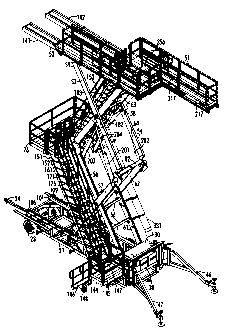
BRIEF DESCRIPTION OF THE DRAWING
[0005] One embodiment of the invention is illustrated in the accompanying
drawings, in
which:
Figure 1 is a perspective view from the left rear of the maintenance stand;
Figure 2 is a perspective view from the right rear of the maintenance stand
with the tow
bar removed;
Figure 3 is a left side view of the maintenance stand;
Figure 4 is a rear view of the maintenance stand;
Figure 5 is a top view of the maintenance stand shown in Figure 3;
Figure 6 is a perspective view of the double scissors linkages;
Figure 7 is a perspective exploded view of the connection between the
intermediate
platform and the scissors linkages;
Figure 8 is a perspective exploded view of the intermediate platform and the
upper
stairway;
Figure 9 is a perspective view of a left side lift lock;
2
CA 02558694 2006-08-30
Figure 10 is an exploded perspective view of the under side of the upper
platform support
frame and its connection to the upper arms of the scissors linkages;
Figure 11A is a perspective view showing a trolley being inserted into a track
on the
underside of the upper platform support frame;
Figure 11 B is an exploded perspective view of the trolley shown in Figure 11
A;
Figure 12 is a perspective view of the upper platforms and their support
frame;
Figure 13 is an exploded perspective view of the rolling center platform;
Figure 14 is an exploded perspective view of a center platform brake support
structure
and brake components;
Figure 15 is an exploded perspective view of the hand operated center platform
brake and
its support structure;
Figure 16 is an exploded perspective view of a foot-operated brake for the
right upper
rolling platform;
Figure 17 is an exploded perspective view of a foot-operated brake for the
left upper
rolling platform, and
Figure 18 is a top view of the upper rolling platforms and their support
frame;
Figure 19 is a section taken on line 19-19 in Figure 18;
Figure 20 is a section taken on line 20-20 in Figure 18;
Figure 21 is a left side view of the upper worker platform shown in Figure 18,
and
Figure 22 is a schematic illustration of a power and control system.
3
CA 02558694 2006-08-30
DETAILED DESCRIPTION OF THE INVENTION
[0006] The maintenance stand shown in Figures 1 through 5 includes a
horizontally
elongated wheeled base frame 21 supported at its front end by a pair of
laterally spaced steerable
front wheels 22, 23 mounted on king pins, not shown, to which a removable
tongue or tow bar
24 is connected through a transverse tie bar 26 of an Ackerman steering
assembly, as shown in
Figure 5. The rear end of the tongue 24 is pivotally connected on a vertical
pivot axis 25 to a
frame member 27 of the base frame 21. The maintenance stand includes a power
module 30 on
the rear end of the base frame 21 and is selectively power steered by a
hydraulic steering ram 28
interconnected between the base frame 21 and the Ackerman steering assembly.
The steering
ram 28 is controlled by a solenoid valve 29 of the control system shown in
Figure 22. The base
frame 21 is supported at its rear end by a pair of laterally spaced rear
wheels 31, 32.
(0007] Referring also to Figure 22, an internal combustion engine 37, housed
in an enclosure
38 of the power module 30, drives a fluid pump 39 supplying pressure fluid to
a fluid motor 36
through a control system including an electrically operated solenoid valve 41
having forward,
reverse and neutral control positions of adjustment. The left rear wheel 31 is
selectively driven
by the fluid motor 36 which has a built in spring biased brake, not shown. The
built in brake is
released when pressurized fluid is supplied to the motor 36. A suitable
commercially available
fluid motor with a built in brake is available from Sauer Daufoss, 500 Barclay
Blvd.,
Lincolnshire, Illinois.
[0008] The base frame 21 is stabilized by right and left outriggers 46, 47
which are pivotally
connected to the right rear and the left rear corners of the base frame on
vertical pivot axes.
Vertically adjustable leveling swivel pads 48 are threadingly mounted on
vertically axes on the
distal ends of the outriggers 46, 47.
4
CA 02558694 2006-08-30
[0009] As shown in Figures 1 through 5, an upper worker platform 51, elongated
horizontally fore and aft in relation to the base frame 21 and in parallel
relation to the base
frame, includes an upper platform support frame 52 which is supported on the
base frame 21 by a
pair of laterally spaced left and right, or first and second, double scissors
linkages 53, 54. The
left double scissor linkage 53 includes a laterally inner lower arm 56, a
laterally outer lower arm
57, a laterally inner upper arm 58 and a laterally outer upper arm 59. The
right double scissors
linkage 54 includes a laterally inner lower arm 61, a laterally outer lower
arm 62, a laterally
inner upper arm 63 and a laterally outer upper arm 64. The laterally inner
lower arms 56, 61 are
rigidly interconnected by cross braces 66 and the laterally inner upper arms
58, 63 are rigidly
interconnected by cross braces 67 and cross braces 68.
[0010] The laterally inner lower arms 56, 61 are pivotally connected near
their mid points to
the laterally outer lower arms 57, 62 respectively, on a laterally extending
horizontal axis 71.
The laterally inner upper arms 58, 63 are pivotally connected near their mid
point near the mid
point of the laterally outer upper arms 59, 64, respectively, on a laterally
extending horizontal
axis 72. As shown in Figure 6, the corresponding lower ends of the laterally
inner lower arms
56, 61 are pivotally connected to the base frame 21 on a laterally extending
horizontal axis 73.
Corresponding upper ends of the laterally inner upper arms 58, 63 are
pivotally connected to the
upper platform support frame 52 on a laterally extending horizontal axis 74.
The corresponding
lower ends of the laterally inner upper arms 58, 67 are pivotally connected to
the corresponding
upper ends of the laterally inner lower arms 56, 62, respectively, and to an
intermediate platform
76, as shown in Figure 7, on a laterally extending horizontal axis 77 by a
pair of pivot pins 78.
The lower ends of the laterally outer upper arms 59, 64 are pivotally
connected to the
corresponding upper ends of the laterally outer lower arms 57, 62 on a
laterally extending
CA 02558694 2006-08-30
horizontal axis 81. The laterally outer upper arms 59, 64 are vertically
aligned with the laterally
outer lower arms 57, 62, respectively; and the laterally inner upper arms 58,
63 are vertically
aligned with the laterally inner lower arms 56, 61, respectively. As shown in
Figures 1, 2, 4 and
6, the upper ends of the laterally outer lower arms 57, 62 are rigidly
interconnected by a
transverse cross brace 82.
[0011] As shown in Figure 6, the lower ends of the laterally outer lower arms
57, 62 are
pivotally connected, respectively, to a pair of trolleys 86, 87 on a laterally
extending pivot axis
88. The trolleys 86, 87 are reverse images of one another. The right lower
trolley 87, shown in
Figure 9, includes a mounting plate 89, support rollers 91, and side thrust
rollers 92, only one of
which is shown. The trolley 87 is supported by a front to rear extending
horizontal trolley track
101 formed by two channels 102, 103 rigidly secured to the top of the right
side of the base
frame 21. In a like manner the trolley 86 is mounted in a trolley track 106
rigidly secured to the
top of the left side of the base frame 21. The tracks 101, 106 and trolleys
86, 87 form track and
follower connections between the laterally lower arms 57, 62 and the base
frame 21. A
horizontal rack 109 with upstanding teeth 111 is secured to the laterally
outer channel 103 by
suitable fasteners 104. The trolley 87 includes a lift lock pawl 113 pivotally
mounted on the
plate 89 by a laterally extending pivot pin 114. The pawl 113 is biased
downwardly by a
compression coil spring 116 whereby its teeth 117 engage the teeth of the rack
109 thereby
locking the trolley 87 to the track 101. A linear fluid actuator in the form
of a double acting
hydraulic ram 121 has its cylinder end pivotally connected to the plate 89 of
the trolley 87 and its
rod end pivotally connected to the pawl 113. The trolley 86 is a reverse image
of trolley 87.
[0012] As shown in Figures 6, 10 and 11A a pair of trolleys 126, 127 have
plates 128, 129
pivotally connected, respectively, to the upper ends of the laterally outer
upper arms 59, 64 on a
6
CA 02558694 2006-08-30
laterally extending horizontal axis 131. Track rollers 132 and side thrust
rollers 133 pivotally
mounted on the plates 136, 137 of the trolleys 126, 127 engage of pair
horizontal parallel trolley
tracks 138, 139 formed on the underside of pair of parallel, laterally spaced
elongated fore and
aft extending platform support sections 141, 142 of the upper platform support
frame 52. The
support sections 141, 142 are rigidly interconnected by a central section 143.
[0013] A removable access platform or side landing module 144 is rigidly
secured to the left
side of the base frame 21, near its rear end, by releasable fasteners, not
shown. The access
platform 144 includes a deck 145, a fixed staircase 146 and a forwardly
projecting part 147 of
the deck 145 disposed laterally between the staircase 146 and the base frame
21. A wheel 148 is
swivel mounted to the underside of the staircase 146.
[0014] A two-part self leveling step staircase 151 is provided between the
forwardly
projecting part 147 of the access platform 144 and the central section 143 of
the upper platform
support frame 52. The staircase 151 includes a first self leveling step
stairway or flight 152
interconnected between the forwardly projecting part 147 and the intermediate
platform 76 and a
second self leveling step stairway or flight 153, between the intermediate
landing 76 and the
central section 143 of the upper platform support frame 52. The first stairway
152, which is
disposed on the left side of the maintenance stand, includes a pair of
parallel lower tread
stringers 161, 162 pivotally connected at their lower ends on a laterally
extending horizontal axis
163 to the forward projecting part 147 of the access platform deck 145. As
shown in Figure 7
the upper ends of the lower tread stringers 161, 162 are pivotally connected
to the intermediate
platform 76 on a laterally extending horizontal pivot axis 164. The lower or
first stairway 152
also includes a pair of laterally spaced parallel upper tread stringers 171,
172. A plurality of
tread assemblies 176 are pivotally connected to the upper and lower tread
stringers 161, 162,
7
CA 02558694 2006-08-30
171, 172. The upper ends of the upper tread stringers 171, 172 are pivotally
connected to the
intermediate platform 76 on axis 77 and the lower ends of the upper tread
stringers are pivotally
connected to the forward projecting part 147 of the access platform deck 145
thus completing a
parallel linkage arrangement of the lower stairway 152.
[0015] As shown in Figures 1, 2, 3, 4 and 8, the upper stairway 153 includes a
pair of parallel
lower tread stringers 181, 182 and a pair of parallel upper tread stringers
183, 184 with a
plurality of tread assemblies 186 pivotally connected to the stringers 181,
182, 183, 184. The
lower ends of the lower stringers 181, 182 are pivotally connected by pins
191, 192, respectively,
to the intermediate platform 76 on pivot axis 77 and the lower ends of the
upper tread stringers
183, 184 are pivotally connected to the intermediate platform 76 and to
upright hand rail posts
186, 187, respectively on the laterally extending horizontal axis 164. The
handrail posts 186,
187 are rigidly secured to the intermediate platform 76 by releasable
fasteners, not shown. As
shown in Figure 3, the upper ends of the lower tread stringers 181, 182 are
pivotally connected to
the upper platform support frame 52 on transverse axis 74, and the upper ends
of the upper tread
stringers, 183, 184 are pivotally connected to the upper platform support
frame 52 on a
transverse axis 191. Appropriate guardrails are provided for the stairways
152, 153 and the
access staircase 145. Also, appropriate removable guardrails are provided for
the access
platform 144, the intermediate platform 76 and the upper platform S 1.
[0016] The upper worker platform 51 is raised and lowered by the two double
scissors
linkages 53, 54 through extension and contraction of four fluid powered linear
actuators 201,
202, 203 and 204 in the form of double acting hydraulic rams each having a
piston and a
cylinder. The actuators 201 and 202 have rod ends pivotally connected to the
laterally outer
upper arms 59, 64, respectively, and their cylinder ends pivotally connected
to the laterally outer
8
CA 02558694 2006-08-30
lower arms 57, 62 respectively. The actuators 203, 204 have their rod ends
pivotally connected
to the laterally inner upper arms 58, 63, respectively, and their cylinder
ends pivotally connected
to the laterally inner lower arms 56, 61 through a cross brace 205, shown in
Figure 6. The
actuators are operated through a fluid control system such as shown in Figure
22, which includes
a solenoid operated control valve 210 having raise, lower and hold positions
of adjustment. A
flow divider 221 provides uniform extensions and contraction of actuators 203,
204 and a flow
divider 212 provides uniform extension and contraction of the actuators 203,
204.
[0017] Referring to Figures 5, 10, 12, 13, 18, 19, 20 and 21, the upper worker
platform
support frame 52 of the upper platform assembly 51 includes the laterally
spaced and
horizontally elongated left and right spaced support sections 141, 142 rigidly
interconnected by
the central section 143. An elongated horizontally shiftable worker platform
216 is mounted on
the left support section 141. An elongated horizontally shiftable worker
platform 217 is mounted
on the right support section 142 and a horizontally shiftable central worker
platform 218 is
mounted on the central support section 143. As shown in Figure 19, rollers 221
mounted on the
rear parts of the support frames 141, 142 provide vertical support for side
channels 224, 226 of
the left rolling platform 216 and for side channels 227, 228 of the right
rolling platform 217. As
shown in Figure 20 and 21, rollers 231 mounted on channels 224, 226 by
brackets 233, 234
engage the undersides of channels 236, 237 of support section 141. The forward
end of the
rolling right platform 217 is stabilized in a similar manner by a pair of
rollers. The rolling center
platform 218 is supported by rollers 251 mounted on the central support
section 143. The rollers
251 run in fore and aft extending channels 252, 253 on the under side of the
rolling center
platform 218. The channels 252, 253 are also shown in Figure 13.
9
CA 02558694 2006-08-30
[0018] A spring loaded manually releasable brake mechanism 261 for the center-
rolling
platform 218 is shown in Figures 12, 14 and 15. A center platform brake mount
262 is rigidly
secured to the forward end of the rolling center platform 218. The brake mount
262 includes a
pair of sockets 263, 264 adapted to receive hollow posts 266, 267. A brake
spring holder 268
with a cylindrical pocket 269 for a coil compression brake spring 271 is
secured to an angle
bracket 272 welded to lower end of the socket 263 by releasable fasteners in
the form of bolts
273 and nuts, not shown. A brake lever 274 with a brake pawl 276 is pivotally
mounted by a
pivot pin 279 on a front to rear extending horizontal axis 277 to a box shaped
bracket 278 welded
to the right side of the socket 263. In the installed condition of the brake
lever 274, a lower end
of a vertical brake rod 281 is pivotally connected to a tab 282 on the brake
lever 274 by a pivot
pin 282. The brake rod 281 is operated by a hand operated brake release lever
283 pivotally
connected to the top of the post 266. The lever 283 has an arm pivotally
connected to the upper
end of the brake rod 281. The pawl 276 engages a front to rear extending rack,
not shown, on
the upper platform support frame 52.
[0019] As shown in Figure 12, a pair of foot release spring loaded brakes 286,
287 for the
left and right rolling upper platforms 216, 217 are mounted on the center
section 143 of the upper
platform support frame 52. The left brake 286, as shown in Figure 17, includes
a housing 288 to
which a brake lever 289 is pivotally connected by a pin 291 which, when
installed, extends
through openings 292, 293 in the housing and an opening 294 in the brake lever
289. A pawl
296 is secured to the brake lever 289 and a coil compression spring 297, which
loosely fits in a
cylindrical part 298, biases the pawl 296 toward an engaged position in which
it engages a rack
299 secured to the right side of the left rolling platform 216. The
horizontally extending portion
301 of the brake lever 289 extends through an opening 302 in the housing and
may be engaged
CA 02558694 2006-08-30
by a workers foot to disengage the brake 286. The brake housing 288 serves as
a convenient
support for a female electrical outlet 303 connected to an electric line 304,
shown in Figure 2,
extending upward from an electric line reel 306 mounted on the base frame 21.
The right foot
operated brake 287, shown in Figure 16 mounted on the center section 143,
includes a housing
311, a brake lever 312 with a rack 313, a pivot pin 314 and a coil compression
spring 316 which
biases the brake lever 312 to a brake engaging position in which the rack 313
engages a front to
rear extending rack 317 secured to the laterally inner side of the right
rolling platform 217, as
shown in Figure 1. The L-shaped brake lever 312 includes a horizontally
extending portion 318,
which can be engaged by the foot of a worker to release the brake. The housing
311 of the brake
for the right rolling worker platform 217 serves as a support for a quick
disconnect coupler 321
at the end of a compressed air hose 322 extending up from a hose reel 323
mounted on the base
frame 21, as shown in Figure 2.
(0020] In addition to equipment supplying electricity and compressed air to
the worker
platform 51, cooling air is supplied to the platform 51 by a duct 331, shown
in Figures 1, 2, 4 and
which includes a rigid duct section 332 mounted on the base frame 21, a rigid
duct section 333
secured to the right laterally inner lower arm 61 of the scissor linkage 54 by
brackets 334, 336,
337, 338, a flexible duct section 339 interconnecting ducts 332 and 333, a
rigid duct section 341
secured to the laterally inner upper arms 63 of the scissor linkage 54 by
brackets 342, 343, 344,
346, a flexible duct section 347 interconnecting rigid duct sections 333 and
341, a rigid duct
section 348 secured to right section 142 of the upper platform support frame
52 by brackets 349
and a flexible duct section interconnecting the rigid duct section 348 and the
rigid duct section
341..
11
CA 02558694 2006-08-30
[0021] The power module 30 can be controlled through a control including a
hand pendant
351 on a flexible cable 352 connected to an electric control panel 353, which
in turn is connected
to the power module 30 and the solenoid valves. The hand pendant 351 allows an
operator to
view all movements of the stand from either front, rear or side positions.
While standing on the
ground, the operator drives the stand to the intended position at the
aircraft, extends and locks the
outriggers 46, 47 in place and raises the platform 51 to the desired height.
The operator then
climbs the stairs to upper central platform section and extends the rolling
platforms to the desired
position.
[0022] The mobile maintenance stand is designed for efficient service of large
airplanes and
helicopters. Its large size gives rise to the need to provide motive power to
move it from storage
to aircraft servicing positions. A portable worker stand 356, shown in Figure
l, 2, 3, 4 and 5,
may be positioned on the central worker platform 218 to give the worker
additional working
height.
12