Note: Descriptions are shown in the official language in which they were submitted.
CA 02558756 2006-09-05
WO 2005/086776 PCT/US2005/007419
Posterior Process Dynamic Spacer
BACKGROUND OF THE INVENTION
The leading cause of lower back pain arises from rupture or degeneration of
lumbar intervertebral discs. Pain in the lower extremities is caused by the
compression
of spinal nerve roots by a bulging disc, while lower back pain is caused by
collapse of
the disc and by the adverse effects of articulation weight through a damaged,
unstable
vertebral j oint.
In some cases, when a patient having a collapsed disc moves in extension
(e.g.,
leans backward), the posterior portion of the annulus fibrosus may further
compress and
extend into the spinal canal. This condition (called "spinal stenosis")
produces a
narrowing of the spinal canal and impingement of tissue upon the spinal cord,
thereby
producing pain.
There have been numerous attempts to provide relief for these afflictions by
providing a spacer that inserts between adjacent spinous processes present in
the
posterior portion of the spinal column. Iii general, these interspinous
implants are
adapted to allow flexion, rotation, translation and lateral bending movement
in the
patient, but resist or limit extension.
US Patent No. 6,068,630 ("Zuchermann") discloses a spinal distraction implant
that alleviates pain associated with spinal stenosis by expanding the volume
in the
spinal canal or neural foramen. Zucherman discloses a plurality of implants
having a
body portion and lateral wings. The body portion is adapted to seat between
the
adjacent spinous processes, while the wings are adapted to prevent lateral
movement of
the body portion, thereby holding it in place between the adjacent spinous
processes.
The designs disclosed in FIGS. 15, 80 and 84 of Zuchermann comprise central
body
having an integral wing.
1
CA 02558756 2006-09-05
WO 2005/086776 PCT/US2005/007419
Although the Zucherman device achieves spinal distraction, it nonetheless
possesses some limitations. First, it is a mufti-piece design, and so is
subject to wear
and implantation complexity. Second, since the Zuchermann central bodies have
at
least one integral wing, the clinician may encounter difficulty in sizing the
central body
independently of delivering the lateral wings. Third, the expansive geometry
of the
disclosed devices may not lend itself to minimally invasive surgical
techniques seeking
to conserve muscle mass and soft tissue in the regions adjacent the spinous
processes.
SUMMARY OF THE INVENTION
The present inventors have developed a number of flexible interspinous devices
having improvements over the conventional devices.
In a first embodiment, the extensions on one side of the implant are made of a
shape memory metal. This implant is inserted into the interspinous space in a
collapsed,
low temperature form. When the implant rises to the temperature of the
patient's body,
the upper and lower extensions made of memory metal transform to the
austenitic phase
to extend upwards and downwards respectfully, thereby bracketing the upper and
lower
spinous processes and locking the implant in place.
In addition, since the shape memory extensions can deform elastically in their
austenitic phase, the ends of the extensions on a lateral side of the implant
can be forced
together, inserted through the interspinous space, and then released, thereby
allowing
the extensions to spring back to their unconstrained shape.
Therefore, in accordance with the present invention, there is provided an
interspinous implant for insertion into an interspinous space between adjacent
spinous
processes, comprising:
a) a central body having an upper surface for bearing against an upper
spinous process, a lower surface for bearing against a lower spinous process,
and first and second side portions,
b) a first upper extension extending upward from the first side portions,
2
CA 02558756 2006-09-05
WO 2005/086776 PCT/US2005/007419
c) a second upper extension extending upward from the second side
portion, the upper extensions collectively defining an upper bracket, and
d) a first lower extension extending downward from the first side portion,
e) a second lower extension extending downward from the second side
portion, the lower extensions collectively defining a lower bracket,
wherein each of the first upper and first lower extension comprises a shape
memory metal.
In a second embodiment, the implant has bases fastened to opposite sides of
the
same spinous process, and the bases are connected by a flexible cord. The cord
is
adapted to have a flexibility and resiliency such that, during extension (when
the
spinous processes move closer towards one another, the flexible cord provides
a soft
stop for the movement of the opposite spinous process, thereby gently limiting
excessive extension.
Therefore, in accordance with the present invention, there is provided an
interspinous implant for insertion into an interspinous space between a first
and second
spinous process, the first spinous process having a first and second side, the
implant
comprising:
a) a first base having a side surface adapted for fixation to a first side of
the
first spinous process,
b) a second base having a side surface adapted for fixation to a second side
of the first spinous process,
a first flexible ligament having a first end connected to the first base and a
second end
connected to the second base.
In a third embodiment, the implant is a three-piece device having a central
body
and a pair of lateral extensions, wherein the extensions are slid through
axial slots in the
central body. Because neither extension is integrally formed to the central
body, the
physician can first view and assess the placement of the central body prior to
adding the
extensions without being shielded by the extension.
3
CA 02558756 2006-09-05
WO 2005/086776 PCT/US2005/007419
Therefore, in accordance with the present invention, there is provided an
interspinous implant for insertion into an interspinous space between a first
and second
spinous process, the implant comprising:
a) a central body having:
i. an upper surface for bearing against an upper spinous process,
ii.a lower surface for bearing against a lower spinous process,
iii.first and second side surfaces, and
iv.first and second axial through-holes, each through-hole extending
from the upper surface to the lower surface,
b) a first extension having an upper end and a lower end, the first extension
extending through the first axial through-hole of the central body,
c) a second extension having an upper end and a lower end, the second
extension extending through the second axial through-hole of the central
body,
wherein the upper ends of the extensions collectively define an upper bracket,
and
wherein the lower ends of the extensions collectively define a lower bracket.
In a fourth embodiment, the implant is a three-piece device having a central
body and a pair of lateral extensions, wherein side surfaces of the central
body are
connected to the extensions. As with the third embodiment, because neither
extension is
integrally formed to the central body, the physician can first view and assess
the
placement of the central body prior to adding the extensions without being
shielded by
the extension.
Therefore, in accordance with the present invention, there is provided an
interspinous implant for insertion into an interspinous space between a first
and second
spinous process, the implant comprising:
a) a central body having:
4
CA 02558756 2006-09-05
WO 2005/086776 PCT/US2005/007419
i.an upper surface for bearing against an upper spinous process,
ii. a lower surface for bearing against a lower spinous process,
iii.first and second side surfaces defining a transverse axis, and
iv.a first opening extending from the first side surface into the body,
b) a first extension having an upper end, a lower end, an inner surface, the
first extension being separate from the central body,
c) a second extension having an upper end, a lower end, an inner surface,
the second extension being separate from the central body,
wherein the first side surface of the central body contacts the inner surface
of the first
extension,
wherein the second side surface of the central body contacts the inner surface
of the
second extension,
wherein the upper ends of the extensions collectively define an upper bracket,
and
wherein the lower ends of the extensions collectively define a lower bracket.
In a fifth embodiment, the interspinous implant has a pair of U-shaped hooks
adapted to cradle the opposing processes and a comlection piece therebetween.
The
hooks have leading and trailing ends and are further adapted to be slid
laterally around
the spinous process.
Therefore, in accordance with the present invention, there is provided an
interspinous implant for insertion into an interspinous space between a first
and second
spinous process, the implant comprising:
a) an upper hook having a leading end, a trailing end, an upper bearing
surface adapted to bear against the first spinous process, and a lower
surface,
5
CA 02558756 2006-09-05
WO 2005/086776 PCT/US2005/007419
b) a lower hook having a leading end, a trailing end, and a lower bearing
surface adapted to bear against the first spinous process, and an upper
surface,
c) a central body having:
i. an upper surface adapted for connection to the lower surface
of the upper hook, and
ii. a lower surface adapted for connection to the upper surface of
the lower hook.
DESCRIPTION OF THE FIGURES
FIGS.la and 1b disclose embodiments of the same memory metal implant of the
present invention in the austentitic and martensitic phases.
FIG.2 discloses the memory metal implant of FIG. 1 after being implanted in
the
interspinous space and returning to its austenitic form.
FIGS. 3a and 3b disclose a second embodiment of the present invention having
two
flexible cords between two bases.
FIG. 3c discloses the implant of FIGS. 3a-b implanted so as to laterally span
an
interspinous space to provide a soft stop for a spinous process during
extension.
FIGS. 4a and 4b disclose components of a third embodiment of the present
invention
wherein the central body has axial openings adapted for the reception of
extensions.
FIG. 4c shows the assembly of the components of FIGS. 4a and 4b.
FIGS. Sa-Sd disclose a fourth embodiment of the present invention wherein the
central
body and extensions are connected by rivets.
6
CA 02558756 2006-09-05
WO 2005/086776 PCT/US2005/007419
FIGS. 6a-6c disclose a fifth embodiment of the present invention having a pair
of U-
shaped hooks.
FIG. 7 is a side view of a functional spinal unit of the human anatomy.
DETAILED DESCRIPTION OF THE INVENTION
For the purposes of the present invention, the term "interspinous" refers to
the
volume located between two adjacent spinous processes of adjacent vertebrae.
The
terms "anterior" and "posterior" are used as they are normally used in spinal
anatomy.
Accordingly, the "anterior" portion of the interspinous device is that portion
rests
relatively close to the spinal cord, while the "posterior" portion of the
interspinous
device is that portion rests relatively close to the skin on the patient's
back. Now
refernng to FIG. 7, there is provided an anatomic "functional spinal unit" or
FSU
comprising an upper vertebrae having an upper vertebral body VU and an upper
spinous
process SPu, a lower vertebra having a lower vertebral body VL having a lower
spinous
process SPL, The vertebral bodies lies in the anterior A portion of the FSU,
while the
spinous processes lie in the posterior portion P of the FSU. Disposed between
the
vertebral bodies is a disc space DISC. Disposed between the spinous process is
an
"interspinous region". Disposed between the spinous process and the vertebral
body of
each vertebra is a lamina L. The supraspinous ligament SSL lies posterior to
the spinous
processes. The posterior longitudinal ligament PLL lies posterior to the
vertebral
bodies.
Now referring to FIG. 1 a, there is provided an interspinous implant 1 for
insertion into an interspinous space between adjacent spinous processes,
comprising:
a) a central body 5 having an upper surface 7 for bearing against an upper
spinous process, a lower surface 9 for bearing against a lower spinous
process, and first 11 and second 13 side portions,
b) a first upper extension 15 extending upward from the first side portion,
7
CA 02558756 2006-09-05
WO 2005/086776 PCT/US2005/007419
c) a second upper extension 17 extending upward from the second side
portion, the upper extensions collectively defining an upper bracket, and
d) a first lower extension 19 extending downward from the first side
portion,
e) a second lower extension 21 extending downward from the second side
portion, the lower extensions collectively defining a lower bracket,
wherein each of the second upper and second lower extensions comprises a shape
memory metal.
In some preferred embodiments, the first upper and first lower extensions are
adapted to extend upwards and downwards in an austenitic phase, and laterally
in the
martensitic phase. This implant is inserted into the interspinous space in a
collapsed,
low temperature (martensitic) form, as shown in FIG. 1b. Now referring to FIG.
la,
when the implant rises to the temperature of the patient's body, the upper and
lower
extensions made of memory metal transform to the austenitic phase to extend
upwards
and downwards respectfully, thereby bracketing the upper and lower spinous
processes
and locking the implant in place.
The austenitic and martensitic forms of the implant are respectively shown in
FIGS. 1 a and 1b. The device as implanted is shown in FIG. 2.
Because the memory-metal induced transformation of each of the second upper
and second lower extensions occur in response to a change in temperature, the
desired
shape changes occur without any action from the surgeon. Accordingly, the
implantation of this device is very simple.
In one preferred embodiment, the side surface of the central body from which
the memory metal extensions extend has a slight recess. This recess reduces
the stress
produced by the tranformation.
8
CA 02558756 2006-09-05
WO 2005/086776 PCT/US2005/007419
In some embodiments, the implant is a unitary body. The unitary nature of the
body
provides for ease of manufacturing and implantation, and reduces the stress on
the
implant.
In some embodiments, the first upper and first lower extensions are adapted to
superelastically extend sideways in a martensitic phase. This embodiment
provides for
a reduced stress upon the implant.
In some embodiments, at least one of the memory metal extensions has a
chamfered
end 23. The chamfer increases the ease of insertion on these extensions into
the
interspinous space. In preferred embodiments, each of the first upper and
first lower
extensions has a chamfered end.
In some embodiments, the upper and lower surfaces of the central body define a
body height HeB, wherein each of the first upper and first lower extensions
have an end
defining an extension height therebetween HE, and wherein the extension height
HE is
less than the central body height HCB. When the extension height HE is less
than the
central body height H~B, the implant may more easily be implanted into the
interspinous
space. Preferably, each end of the second upper and second lower extensions
contact
one another in the martensitic phase.
Preferably, the shape memory material is a nickel-titanium alloy.
Now referring to FIGS. 3a and 3b, there is provided an interspinous implant 31
for insertion into an interspinous space between a first and second spinous
process, the
first spinous process having a first and second side, the implant comprising:
a) a first base 33 having a side surface 35 adapted for fixation to a first
side of
the first spinous process,
b) a second base 37 having a side surface 39 adapted for fixation to a second
side of the first spinous process, and
c) a first flexible ligament 41 having a first end 43 connected to the first
base
and a second end 45 connected to the second base.
9
CA 02558756 2006-09-05
WO 2005/086776 PCT/US2005/007419
Now referring to FIG. 3a, in this embodiment, the implant has bases adapted to
fasten to opposite sides of the same spinous process, and the bases are
connected by a
flexible cord. The surgeon simply takes the implant in its open form (as in
FIG. 3b),
inserts the leading base of the implant laterally into a first side of the
interspinous
space, and then pulls the leading end as it emerges from the second side of
the
interspinous space. The surgeon then folds the implant so that each base abuts
its
respective side of the lower spinous process. Now referring to FIG. 3c, the
surgeon then
adjusts the position of the device so that its apex 46 of the ligament is at a
position
between the spinous processes that will provide the appropriate amount of
distraction
for the patient's relief of pain. The surgeon then fastens the bases to the
lower spinous
process.
The cord has flexibility and resiliency such that, during extension (when the
spinous processes move closer towards one another, the flexible cord provides
a soft
stop for the movement of the opposite spinous process, thereby gently limiting
excessive extension. Since the limitation on extension is provided gradually
and gently
(i.e., it is not a hard stop), it is believed that there will be less wear of
the respective
contacting surfaces, thereby prolonging the life of the implant.
Referring to FIG.3a, in some embodiments, each of the first and second bases
comprises an upper surface 47,48, wherein the first end of the first flexible
ligament is
connected to the upper surface of the first base, and the second end of the
first flexible
ligament is connected to the upper surface of the second base. When the
ligament is
connected to the upper surfaces of bases (as opposed to the side surfaces),
the length of
and stresses upon the ligaments are minimized.
In some embodiments, the upper surfaces of each base form an angle of no more
than 180 degrees, preferably less than 180 degrees, more preferably between
100
degrees and less than 180 degrees. In this range, the ligament takes on an
arcuate shape
well suited to flexibly accept and resist extension of the upper spinous
process.
CA 02558756 2006-09-05
WO 2005/086776 PCT/US2005/007419
In some embodiments, the implant further comprises a second flexible ligament
49 having a first end 51 connected to the first base and a second end 52
connected to
the second base. The provision of the second flexible ligament is advantageous
because
the spinous processes have a proportionally larger dimension from the anterior
to the
posterior (thereby causing a posterior narrowing of the interspinous space).
In addition,
the provision of a second ligament distributes compressive extension loads
more evenly
along the processes.
In some embodiments, each base comprises a transverse hole 50 through
passing through the side surface adapted for fixation to a side of a spinous
process. The
tranverse holes allows the surgeon to pass a fixation device (such as a screw)
through
each hole, thereby fixing the implant to the lower spinous process.
In some embodiments, the first ligament is made of a flexible polymer, and is
preferably selected from the group consisting of polyester (preferably,
DacronR) and
polyethylene. Preferably, the ligament is a longitudinal element having a
thickness of
between 3 cm and ~ cm. The selection of a thickness in this range, along with
the
selection of a flexible polymer as the material of construction, should
provide a
ligament that is suitably flexible to provide a gentle stop to extreme
extension.
In other embodiments, the ligament takes the form of a fabric or strap. When
the
fabric embodiment is selected, it is desirable to use only a single ligament.
In some embodiments, the bases are made of a material selected from the group
consisting of ultra high molecular weight polyethylene and PEEK. These
materials are
well known biocompatible materials of construction for load bearing medical
devices.
Now referring to FIGS. 4a-c, there is provided an interspinous implant 51 for
insertion into an interspinous space between a first and second spinous
process, the
implant comprising:
a) a central body 53 having:
11
CA 02558756 2006-09-05
WO 2005/086776 PCT/US2005/007419
i. an upper surface 55 for bearing against an upper spinous
process,
ii. a lower surface 57 for bearing against a lower spinous
process,
iii. first 59 and second 61 side surfaces, and
iv. first 63 and second 65 axial through-holes, each through-hole
extending from the upper surface to the lower surface,
b) a first extension 67 having an upper end 69 and a lower end 71 , the first
extension extending through the first axial through-hole of the central
body,
c) a second extension 73 having an upper end 75 and a lower end 77, the
second extension extending through the second axial through-hole of
the central body,
wherein the upper ends of the extensions collectively define an upper bracket,
and
wherein the lower ends of the extensions collectively define a lower bracket.
In use, the surgeon first orients the central body portion of the implant so
that its
throughholes run in the (axial) saggital plane. The surgeon then inserts the
oriented
central body laterally into the interspinous space so that one axial
throughhole is
disposed on one side of the interspinous space and the second axial
throughhole is
disposed on the second side of the interspinous space. The surgeon then
adjusts the
position of the device so that it is approximately centered about each spinous
process.
The surgeon then inserts the extensions into the respective axial throughholes
to secure
the implant to the spinous processes.
Because neither extension is connected to the central body during insertion,
but
rather may be inserted separately, the physician can first view and assess the
placement
of the central body prior to adding the extensions without being visually
shielded by the
extension. In addition, the separate insertion of the extensions lowers the
lateral span of
the implant during insertion, thereby causing less damage to the sensitive
musculature
surrounding the interspinous space.
12
CA 02558756 2006-09-05
WO 2005/086776 PCT/US2005/007419
In addition, since the human spinous process is often a source of significant
interindividual variation, each of the central body and extensions may be
provided in
different shapes and sizes, so that the surgeon can infra-operatively select
the
appropriate central body and extensions, thereby providing greater surface
area contact
between the implant and the adjacent processes and minimizing stresses.
Different
shapes (which, in some cases, have very small lateral profiles) may be
suitable for
different anatomical interspinous spaces. In addition, the central body may be
provided
in different heights so that the surgeon ca~i select the central body
producing the most
appropriate degree of interspinous space distraction.
In some embodiments, the central body has a saggital profile comprising a
substantially parallel anterior portion and an inwardly tapering posterior
portion. It is
believed that this profile more closely resembles the profile of the
interspinous space,
and so should provide for more contact therebetween and reduced stresses.
Since the physiologic loads experienced by central body during extension are
relatively low (e.g., only about 20 pounds-force), the central body may be
made of
materials such as UWMWPE or PEEK. These materials are also preferred for the
suitability in medical imaging procedures.
In some embodiments, the extensions comprise a centrally located recess 79
having a length substantially similar to the height of the central body. The
recess
allows the extension to snap into place when it is appropriately situated
within the
central body, thereby insuring a secure fit. When the extension is made of a
metal
material (such as a titanium alloy), the extension may further desirably
comprise an
internal slot (not shown) adapted to behave in a spring-like manner during
extension
insertion, thereby facilitating the insertion of the extension.
Now refernng to FIG. 5a, there is provided an interspinous implant 101 for
insertion into an interspinous space between a first and second spinous
process, the
implant comprising:
13
CA 02558756 2006-09-05
WO 2005/086776 PCT/US2005/007419
a) a central body 103 having:
i. an upper surface 105 for bearing against an upper spinous
process,
ii. a lower surface 107 for bearing against a lower spinous
process,
iii. first 109 and second 111 side surfaces defining a transverse
axis, and
iv. a transverse 113 through-hole extending from the first side
surface to the second side surface,
b) a first extension 121 having an upper end 123, a lower end 125, an inner
surface 127, and a transverse throughhole 129, the inner surface of the first
extension contacting the first side surface of the central body and aligning
the transverse througholes,
c) a second extension 131 having an upper end 133, a lower end 135, an
inner surface 137, and a tranverse throughhole 139, the inner surface of the
second extension contacting the second side surface of the central body and
aligning the transverse througholes, and
d) a rivet adapted to connect the extensions to the central body.
wherein the upper ends of the extensions collectively define an upper bracket,
and
wherein the lower ends of the extensions collectively define a lower bracket.
W use, the surgeon first inserts the central body laterally into the
interspinous
space so that one opening of the tranverse throughhole is disposed on one side
of the
interspinous space and the second opening of the throughhole is disposed on
the second
side of the interspinous space. The surgeon then adjusts the position of the
device so
that it is approximately centered about each spinous process, and orients the
central
body portion of the implant so that its throughhole runs in the medial-lateral
plane.
14
CA 02558756 2006-09-05
WO 2005/086776 PCT/US2005/007419
Next, the surgeon selects the appropriate extensions and places connecting
pins
through the throughholes of the extensions.
In some embodiments, as in FIG. 5b, the extensions are spaced from each other
a distance that is substantially greater than the width of the spinous
process. Since the
supraspinous ligament should provide a tight grip upon the inserted central
body, there
should be no need for fastening the extensions to the spinous process. In this
instance,
the extensions merely serve as stops of excessive medial-lateral movement of
the
central body. Accordingly, providing a space between the side surfaces spinous
processes and the inner surfaces of the extensions should minimize wear.
In some embodiments, the extensions have an inner surface 144 having a
convex contour and an outer surface 140 having a concave contour. As shown in
FIG.
5b, tlus convex contour is preferably adapted to match the contour of the
spinous
process. This contour should minimize wear of and stress upon the extension.
The
concave contour is preferably adapted to match the erector spinae portion of
the low
back musculature.
In some embodiments, the extensions have an anterior surface 142 having a
concave contour 143. As shown in FIG. 5c, this concave contour is preferably
adapted
to match the convex contour of the lamina arch portion of the vertebral body.
This
contour should minimize wear of and stress upon the extension, and be less
invasive to
the patient's soft tissues.
Referring back to FIG. 5a, the rivet may include any conventional riveting
assembly. In some embodiments, the rivet comprises:
i) a first connecting pin 141 adapted to fit in the first transverse
throughole
and having a male end 143, and
ii) a second connecting pin 145 adapted to fit in the second transverse
throughole and having a female end 147.
CA 02558756 2006-09-05
WO 2005/086776 PCT/US2005/007419
In the embodiment shown in FIG. 5a, the rivets are shown as being separately
constructed from the extensions. However, in other embodiments, the rivets may
be
integral with the extensions. Similarly, each side of the central body may be
separately
riveted to its respective extension.
In some embodiments, as shown in FIG. 5d, the rivet is located about in the
center of the extension. In other embodiments, as shown in FIG. 5c, the rivet
149 is
located in the bottom half of the extension. It is believed that locating the
rivet in the
bottom half of the extensions desirably provides a good match fit with the
bony
contours of the vertebral body.
The implants of FIGS. Sa-d may be suitably manufactured from any suitable
biomaterial, including metals such as titanium alloys, chromium-cobalt alloys
and
stainless steel) and polymers (such as PEEK, carbon fiber-polymer composites
and
ITHMWPE. In peferred embodiments, the central body is made of UHMWPE ( to
provide moderate stiffness) and the extensions are made of a carbon fiber-PEEK
composite (to provide stiffness to the extensions).
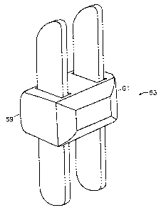
Now refernng to FIGS. 6a-c, there is provided an interspinous implant 151 for
insertion into an interspinous space between a first and second spinous
process, the
implant comprising:
a) an upper hook 153 having a leading end 155, a trailing end 157, an
upper bearing surface 159 adapted to bear against the first spinous process,
and a lower surface,
b) a lower hook 163 having a leading end 165, a trailing end 167, and a
lower bearing surface 169 adapted to bear against the first spinous process,
and an upper surface,
c) a central body 171 having:
16
CA 02558756 2006-09-05
WO 2005/086776 PCT/US2005/007419
i. an upper surface 173 adapted for connection to the lower
surface of the upper hook, and
ii. a lower surface 174 adapted for connection to the upper
surface of the lower hook.
Now referring to FIG. 6a, the surgeon simply inserts a leading base of the
upper
hook laterally into a first side of the interspinous space, and then pulls the
leading end
laterally and upward as it emerges from the second side of the interspinous
space. The
surgeon then repeats tlus process for the lower hook, so that each hooks
envelops its
respective side of the upper and lower spinous processes. The surgeon then
inserts the
central body into the space between the hooks and connects each hook to the
central
body, thereby fixing the implant. FIG. 6b shows the assembled implant.
In some embodiments, the leading and trailing ends of the upper hook extend in
substantially a first same direction (more preferably, upward), and the
leading and
trailing ends of the lower hook extend in substantially a second same
direction (more
preferably, downward). In this condition, the profile of the implant is
relatively low.
In some embodiments, the upper surface of the central body is adapted for
connection to the lower surface of the upper hook by a male-female connection.
In
preferred embodiments, thereof the upper surface of the central body is
adapted for
connection to the lower surface of the upper hook by a dovetail connection
176. The
dovetail connection is believed to produce a highly secure fixation.
In some embodiments, the upper surface of the central body has a female recess
traversing the upper surface in a direction from the leading end to the
trailing end. In
others, the upper surface of the central body has a projection 177 traversing
the upper
surface in a direction from the leading end to the trailing end. In each of
these cases, the
orientation of the mating feature allows fixation to occur in the same motion
as
insertion of the central body. In preferred embodiments thereof, the upper
surface of the
central body has a dovetail feature traversing the upper surface in a
direction from the
leading end to the trailing end.
17