Note: Descriptions are shown in the official language in which they were submitted.
CA 02558831 2006-09-07
WO 2005/089142 PCT/US2005/007469
COATED PISTON PIN
TECHNICAL FIELD
The present invention relates to internal combustion engines. More
particularly, the present
invention relates to a coated piston pin for shiflably connecting a connecting
rod to a piston.
BACKGROUND OF THE 1NVENTI~N
The moving parts of an internal combustion engine serve an important function
in turning
heat energy into mechanical energy. In a conventional internal combustion
engine that has
reciprocating pistons, the moving parts of the engine further convert
reciprocal motion into
rotary motion. Some of the principal moving parts of an internal combustion
engine are the
piston assembly, connecting rods, and a crankshaft assembly. The burning of
the fuel-air
mixture within the cylinder exerts a pressure thus causing it to reciprocate
within the
cylinder. The reciprocation of the piston is transmitted by the connecting rod
to the
crankshaft. The action of the connecting rod and crankshaft converts the
reciprocation of the
piston to a rotary motion.
A prior art piston, piston pin, and connecting rod are depicted in prior art
Figure 1. As noted
in Figure 2, a typical piston has a head and a skirt. The head has a plurality
of lands for
supporting respective piston rings. A piston pin boss is defined in the skirt
of the piston. A
groove may be provided in the skirt for locking a piston pin snap ring for
securing the piston
pin in the piston. Alternatively, a threaded hole that intersects the piston
pin boss may be
provided for a piston pin lock screw.
The piston is attached to the connecting rod by a piston pin (wrist pin) see
Figures 3a, 3b,
prior art. The pin passes through the piston pin bosses of this piston and
through the upper
end of the connecting rod. The upper end of the connecting rod rides within
the piston in the
middle of the piston pin. Piston pins are typically made of alloy steel with a
precision finish
and are case hardened and sometimes chromium plated to increase their wearing
qualities.
Referring again to Figure l, connecting rods must be light and yet strong
enough to transmit
the thrust of the piston to the crankshaft. Connecting rods are typically drop
forged from a
steel alloy capable of withstanding heavy loads without bending or twisting.
Bores at the
upper (small end) and lower (big end) ends of the connecting rods are machined
to permit
1
CA 02558831 2006-09-07
WO 2005/089142 PCT/US2005/007469
accurate fitting of bearings. The upper end of the connecting rod is connected
to the piston
by the piston pin. In the prior art, the upper bore (pin bore) of the
connecting rod has a solid
bearing (bushing) of bronze or similar material disposed therein that is in
contact with the
piston pin. As the lower end of the connecting rod revolves with the
crankshaft, the upper
end shifts back and forth on the piston pin. Although this movement is slight,
in the past a
bushing has been found necessary because of the high pressure and temperatures
experienced.
There is a need in the industry to minimize the number of components
comprising the
moving parts of an internal combustion engine, as well as to minimize the
number of steps
necessary in their production. It would be a significant advantage if the
solid bearing in the
upper bore of the connecting rod could be eliminated. In the past, the bushing
typically must
be purchased from an outside source and then pressed into the pin bore of the
connecting rod.
Additionally, the inside diameter of the bushing must then be machined to
achieve the final
surface necessary. It would be a decided advantage to eliminate the need for
the bushing and
further to eliminate the step of machining the inside diameter of the bushing.
SUMIyIARY OF THE INVENTION
The present invention substantially meets the aforementioned needs of the
industry. By
providing a suitable coating on the piston pin, the need for a solid bushing
in the connecting
rod pin bore is eliminated. This allows the piston pin to come into direct
surface-to-surface
contact with the connection rod and the piston. Preferably, the coating is
chromium-nitride
(Cr-Nitride or Cr-N). The Cr-Nitride coating is preferably applied by physical
vapor
deposition (PVD). Preferably a centerless buff"mg operation may be performed
on the coated
piston pin prior to installation. Preferably, the coating thickness is between
l and 10 microns.
There are no known limitations of the type of piston that the coated piston
pin may be used
with. Accordingly, the coated piston pin may be used with aluminum pistons of
varying
strength as well as steel pistons.
The present invention is a piston pin including a tubular body having a
cylindrical exterior
margin, the exterior margin being shiftably matable with an inside margin of a
pin bore of a
connecting rod, the margin of the pin bore having a surface formed of the
material forming
the connecting rod, the mating being in a surface to surface engagement. The
present
2
CA 02558831 2006-09-07
WO 2005/089142 PCT/US2005/007469
invention is further a method of forming a piston pin and a piston pin,
connecting rod
combination.
A BRIEF DESCRIPTION OF THE DRAWINGS
Figure 1 is a prior art exploded depiction of a piston assembly, piston pin,
and a connecting
rod;
Figure 2 is a prior art cut-away depiction of a piston;
Io
Figure 3 is a prior art depiction of a piston pin partially disposed in a
piston;
Figure 3b is a prior art depiction of a piston pin partially disposed in a
piston;
Figure 4 is a perspective view of a piston pin made according to the present
invention;
Figure 5 is a perspective view of a connecting rod made according to the
present invention;
Figure 6 is a cut-away depiction of a deposition chamber for depositing the
coating of the
present invention; and
Figure 7 is a perspective view of a centerless buffing operation.
DETAILED DESCRIPTION OF THE DRAWINGS
The piston pin and connecting rod of the present invention are shown generally
at I O and 20,
respectively, in Figures 4 and 5.
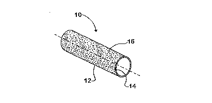
The piston pin 10 has a generally tubular body I2. A lightening bore 14 is
defined in the
body I2 concentric with the longitudinal of the piston pin I0.
A coating 16 is applied to the external margin to the tubular body 12, The
coating 16 is
described in greater detail below. The coating 16 when applied becomes the
external margin
of the piston pin 10.
3
CA 02558831 2006-09-07
WO 2005/089142 PCT/US2005/007469
The connecting rod 20, depicted in Figure S, includes an elongated rod arm 22.
A large end
24 is disposed at a first end of the rod arm 22. The large end 24 is designed
to be rotatably
engaged to a journal on the crankshaft of the engine.
A small end 26 is disposed at a second end of the rod arm 22. The small end 26
has a pin
bore 28 defined therethrough. The pin bore 28 is formed concentric with the
longitudinal of
the small end 26. Notably, the interior margin of pin bore 28 does not include
a bushing and
is formed of the same material as that forming the remainder of the structure
of the
connecting rod 20. Accordingly, the inside diameter of the pin bore 28 is in
direct surface to
surface contact with the coating 16 of the piston pin 10 when the piston pin
10 is inserted into
the pin bore 28 of the connecting rod 20 without the interposition of a
bearing.
The coating 16 ' is preferably chromium nitride (Cr-I~. The chromium nitride
coating is a
wear resistant coating preferably formed on the outside margin of the tubular
body 12 of the
piston pin 10 .by physical vapor deposition process. The chromium nitride
coating has high
hardness, excellent oxidation resistance, and a low coefficient of friction:
The coating 16 is
typically metallic silver in color and is similar in appearance to polished
stainless steel. The
chromium nitride coating 16 has excellent adhesion to the piston pin 10. The
coating 16 is
typically applied in a relatively low temperature deposition process. This
permits coating
piston pin 10 without causing distortion, allowing the coating of the close
tolerance, precision
piston pin 10.
As noted above, the coating 16 is preferably applied by physical vapor
deposition (PVD)
processes. PVD covers a broad class of vacuum coating processes in which
material is
physically removed from a source by evaporation or sputtering; transported
through a
vacuum or partial vacuum by the energy of the vapor particles, and condensed
as a film on
the surface of a substrate (piston pin 10 in this case). Chemical compounds
are deposited by
either using a similar source material, or by introducing a gas (nitrogen,
oxygen or simple
hydrogens) containing the desired reactants, which react with metals) from the
PVD source.
4
CA 02558831 2006-09-07
WO 2005/089142 PCT/US2005/007469
A schematic of a typical chamber for imparting a chromium nitride coating of a
substrate by a
PVD process is depicted in Figure 6. The process of deposition consists of a
number of
phases:
chamber evacuation;
heating and cleaning of the substrate;
conditioning of the substrate;
coating the substrate; and
cooling and removal of the coated substrate.
The chamber is evacuated in order to remove all possible contaminants and to
achieve the
correct operating pressure for the process. The substrate is heated using
either radiant heaters
or "ion bombardment" which serves to remove adsorbed contamination from the
surface.
Cleaning takes place through a combination of ion bombardment (sputtering) and
activated
chemical cleaning using hydrogen. The hot piston pin 10 (typically between
200C and 450C)
is "conditioned" by running the evaporation sources for a short time while a
high voltage
(around 1000 volts) is applied to the piston pin 10. The process produces a
mixed layer at the
surface leading to enhanced adhesion of the coating 16. Coating is undertaken
by switching
on all evaporation sources, reducing the voltage to around 200 volts and
admitting the
necessary gases to produce the compound required. Because the piston pin 10 is
hot at the
end of the coating cycle, it is necessary to allow the piston pin 10 to cool
to below about
2000 before removing the piston pin 10 from the chamber to avoid discoloring
any uncoated
areas.
In the preferred embodiment, the chromium nitride coating 16 is applied to the
piston pin 10
to a thickness of between 1 and 10 microns and is preferably about 5 microns.
After the coating 16 is applied to the piston pin 10, the piston pin 10 is
preferably subjected
to a centerless buffing operation. In a centerless bufFmg operation, the
piston pin 10 is
supported between counter rotating buff'mg wheels, as depicted in Figure 7.
Such buffing
imparts a near mirror finish to the outside margin of the coating 16.
5
CA 02558831 2006-09-07
WO 2005/089142 PCT/US2005/007469
While a number of presently preferred embodiments of the invention have been
described, it
should be appreciated the inventive principles can be applied to other
embodiments falling
within the scope of the following claims.
6