Language selection

Search

Patent 2559046 Summary

Third-party information liability

Some of the information on this Web page has been provided by external sources. The Government of Canada is not responsible for the accuracy, reliability or currency of the information supplied by external sources. Users wishing to rely upon this information should consult directly with the source of the information. Content provided by external sources is not subject to official languages, privacy and accessibility requirements.

Claims and Abstract availability

Any discrepancies in the text and image of the Claims and Abstract are due to differing posting times. Text of the Claims and Abstract are posted:

  • At the time the application is open to public inspection;
  • At the time of issue of the patent (grant).
(12) Patent: (11) CA 2559046
(54) English Title: RAILWAY BOGIE
(54) French Title: BOGIE DE VOIE FERREE
Status: Expired and beyond the Period of Reversal
Bibliographic Data
(51) International Patent Classification (IPC):
  • B61F 5/30 (2006.01)
(72) Inventors :
  • GEDENK, VOLKER (Germany)
  • HOPPMANN, FRIEDRICH (Germany)
  • SCHMIECHEN, ROLF (Germany)
  • SKILLER, JOHN
(73) Owners :
  • AB SKF
  • CONTITECH LUFTFEDERSYSTEME GMBH
(71) Applicants :
  • AB SKF (Sweden)
  • CONTITECH LUFTFEDERSYSTEME GMBH (Germany)
(74) Agent: SMART & BIGGAR LP
(74) Associate agent:
(45) Issued: 2012-09-11
(86) PCT Filing Date: 2004-03-26
(87) Open to Public Inspection: 2005-10-06
Examination requested: 2009-03-26
Availability of licence: N/A
Dedicated to the Public: N/A
(25) Language of filing: English

Patent Cooperation Treaty (PCT): Yes
(86) PCT Filing Number: PCT/EP2004/003197
(87) International Publication Number: WO 2005091698
(85) National Entry: 2006-09-08

(30) Application Priority Data: None

Abstracts

English Abstract


A railway bogie comprising at least one hydraulic spring (20) having a housing
being required for a functionality of said hydraulic spring and an axlebox
(10) is characterized by the fact that at least a part of said axlebox forms
at least a part of said housing.


French Abstract

Cette invention se rapporte à un bogie de voie ferrée, qui comprend au moins un ressort hydraulique présentant un logement nécessaire pour le fonctionnement du ressort hydraulique et une boîte d'essieu, ce bogie se caractérisant par le fait qu'au moins une partie de la boîte d'essieu forme au moins une partie du logement.

Claims

Note: Claims are shown in the official language in which they were submitted.

6
CLAIMS:
1. Axlebox-spring-unit of a railway bogie comprising at least one hydraulic
spring having a housing being required for a functionality of said hydraulic
spring and
an axlebox;
wherein at least a part of said axlebox forms at least a part of said
housing; and
wherein said part of said axlebox forms at least a part of a boundary of
a volume for a hydraulic fluid of said hydraulic spring.
2. Axlebox-spring-unit of claim 1, whereby said part of said axlebox
comprises a cup shaped region of said axlebox.
3. Axlebox-spring-unit of one of claims 1 or 2, whereby a spring element of
said hydraulic spring is connected to said part of said axlebox.
4. Axlebox-spring-unit of claim 3, whereby said spring element is secured
to said part of said axlebox via a sealing device.
5. Axlebox-spring-unit of claim 4, whereby said sealing device is a ring
being screwed on said part of said axlebox.
6. Axlebox-spring-unit of one of claims 3 or 5, whereby said spring
element comprises at least one elastomeric element which is directly attached
to said
part of said axlebox.
7. Axlebox-spring-unit of one of claims 3 to 6, whereby said spring
element comprises a centrepiece which extends into said volume for said
hydraulic
fluid forming a plunger shaped region.

7
8. Axlebox-spring-unit of one of claims 3 to 7, whereby said spring
element comprises elastomeric elements and rigid elements in an alternating
succession.
9. Axlebox-spring-unit of claim 8, whereby said elastomeric and rigid
elements are sleeve shaped.
10. Axlebox-spring-unit of one of claims 8 or 9, whereby said elastomeric
elements are connected to said rigid elements or said centrepiece by way of
vulcanisation.

Description

Note: Descriptions are shown in the official language in which they were submitted.


CA 02559046 2006-09-08
WO 2005/091698 PCT/EP2004/003197
s Description
Railway bogie
The invention relates to a railway bogie comprising at least one hydraulic
spring
having a housing being required for a functionality of said hydraulic spring
and an
axlebox.
From UIC standard a bogie with helical springs is well known,. whereby the
axlebox
suspension consists of helical springs in combination with friction damping.
Thereby the springs rest on support arms integral with the lower part of the
axlebox
housing and are connected with the bogie frame using caps integral with the
bogie
frame for taking up the top of the springs.
US 2002-0089102 Al discloses a hydraulic spring comprising a membrane. Therein
it is also disclosed that said hydraulic spring is for use in rail vehicles
especially as a
primary spring.
Further the catalogue of the company ContiTech Luftfedersysteme GmbH in
Hannover, Germany, "Air Spring Systems for Modern Rail Vehicles", printed and
distributed in October 1998 discloses the use of hydraulic springs comprising
a
membrane in two-axle bogies.
CONFIRMATION COPY

CA 02559046 2012-05-04
26675-18
2
Some embodiments of the present invention may provide an improved railway
bogie
comprising at least an axlebox and a hydraulic spring, so that the railway
bogie has a
simplified build-up and is therewith cheaper to produce.
According to an aspect of the invention there is provided axlebox-spring-unit
of a
railway bogie comprising at least one hydraulic spring having a housing being
required for a functionality of said hydraulic spring and an axlebox; wherein
at least a
part of said axlebox forms at least a part of said housing; and wherein said
part of
said axlebox forms at least a part of a boundary of a volume for a hydraulic
fluid of
said hydraulic spring.
By the fact that an anyway existing part of the axlebox is designed and used
to form a
part of the housing of the hydraulic spring the number of components is
reduced in
total so that a lower fault liability and a more favourable cost position can
be
achieved.
Further advantages, features and details of the invention are described with
respect
to one preferred embodiment of the invention with reference to the drawings
wherein:
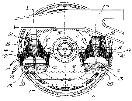
Figure 1 is a longitudinal cross section in the region of one wheel of a
bogie and
Figure 2 is a sectional view along the line BB of Figure 1.
Figure 1 shows a longitudinal cross section in the region of one wheel 2 of a
bogie of
the so-called Y 25 type, whereby the cut is directed according to a plane
being
defined by the axes of rotational symmetry of a first and second hydraulic
spring.
The pictured section of the bogie comprises an axlebox 10 with a rolling
bearing 4

CA 02559046 2006-09-08
WO 2005/091698 PCT/EP2004/003197
3
mounted in a middle region of the axlebox 10. The rolling bearing 4 supports
one
end of one of the two axles of the bogie.
A base of the axlebox 10 is extended to the left and the right side forming a
cup
shaped region 12 at each of said sides. Each of said hydraulic springs
comprises a
spring element 20, which is attached to each of said cup shaped regions 12 of
the
axlebox 10. A metallic centrepiece 26 is located in the centre of each of the
spring
elements 20.
These two centrepieces 26 are attached to one bridging adapter 50. Therefore
the
centrepieces 26 and the bridging adapter 50 have bores for connecting the
centrepieces 26 with the bridging adapter 50 via two bolts 52 pictured uncut
in
Figure 1 and 2. In other embodiments the bolts 52 can be integral parts of the
centrepieces 26 or of the bridging adapter 50 or the centrepieces 26 can be
connected to the bridging adapter 50 by any other connecting means.
The bridging adapter 50 is attached to a longeron of a frame 6 of the bogie,
whereby
this longeron extends in a longitudinal direction parallel to the rails and is
pictured
uncut in Figure 1. Preferably the bridging adapter 50 is connected to the
bogie
frame 6 by welding.
In the following just that left cup shaped region 12 in connection with the
left spring
element 20 is described in detail, because the same applies to the right cup
shaped
region 12 in connection with the right spring element 20. Therefore Figure 2
shows
a sectional view along the line BB of Figure 1. The spring element 20
comprises
sleeve shaped elastomeric elements 22 and intermediate sleeve shaped metallic
elements 24 in an alternating succession, whereby the elastomeric and the
metallic
elements 22 and 24 are connected by way of vulcanisation. Also the centrepiece
26
is connected by way of vulcanisation to its adjacent elastomeric element 22.

CA 02559046 2006-09-08
WO 2005/091698 PCT/EP2004/003197
4
The spring element 20 is secured to the respective cup shaped region 12 of the
axlebox 10 via a sealing ring 42, which is attached to the axlebox 10 via
screws 44.
In other embodiments the spring element 20 also can be directly vulcanised to
the
cup shaped region 12. The spring elements 20 forms together with the
respective
cup shaped region 12 of the axlebox 10 a volume for a fluid 30 particularly a
hydraulic fluid. This volume is at least partly filled with the fluid 30. The
centrepiece 26 is prolonged into said volume forming a plunger shaped region
28.
Thereby at least a disk shaped region at the end of the plunger shaped region
28 is
dipped into the fluid 30, so that this arrangement fulfils the function of a
damper. So
the cup shaped region 12 of the axlebox 10 together with the respective spring
element 20 and the fluid 30 form together the hydraulic spring.
In another embodiment of the invention a hydraulic spring can be used, e.g.
according to the already cited US 2002-0089102 Al, comprising a membrane
instead of the plunger shaped section 28 of the centrepiece. 26, whereby the
cup
shaped region 12 of the axlebox 10 is then also one part of the housing of the
hydraulic spring. . .

CA 02559046 2006-09-08
WO 2005/091698 PCT/EP2004/003197
List of reference signs
5
2 wheel
4 rolling bearing
6 bogie frame
10 axlebox
12 cup shaped region
spring element
22 elastomeric element
15 24 metallic element
26 centrepiece
28 plunger shaped region
fluid
42 sealing ring
44 screw
50 bridging adapter
52 bolt

Representative Drawing
A single figure which represents the drawing illustrating the invention.
Administrative Status

2024-08-01:As part of the Next Generation Patents (NGP) transition, the Canadian Patents Database (CPD) now contains a more detailed Event History, which replicates the Event Log of our new back-office solution.

Please note that "Inactive:" events refers to events no longer in use in our new back-office solution.

For a clearer understanding of the status of the application/patent presented on this page, the site Disclaimer , as well as the definitions for Patent , Event History , Maintenance Fee  and Payment History  should be consulted.

Event History

Description Date
Time Limit for Reversal Expired 2022-03-01
Letter Sent 2021-03-26
Letter Sent 2021-03-01
Letter Sent 2020-08-31
Inactive: COVID 19 - Deadline extended 2020-08-19
Inactive: COVID 19 - Deadline extended 2020-08-06
Inactive: COVID 19 - Deadline extended 2020-07-16
Inactive: COVID 19 - Deadline extended 2020-07-02
Inactive: COVID 19 - Deadline extended 2020-06-10
Inactive: COVID 19 - Deadline extended 2020-05-28
Inactive: COVID 19 - Deadline extended 2020-05-14
Inactive: COVID 19 - Deadline extended 2020-04-28
Inactive: COVID 19 - Deadline extended 2020-03-29
Common Representative Appointed 2019-10-30
Change of Address or Method of Correspondence Request Received 2018-03-28
Grant by Issuance 2012-09-11
Inactive: Cover page published 2012-09-10
Inactive: Final fee received 2012-06-21
Pre-grant 2012-06-21
Notice of Allowance is Issued 2012-06-01
Letter Sent 2012-06-01
Notice of Allowance is Issued 2012-06-01
Inactive: Approved for allowance (AFA) 2012-05-30
Amendment Received - Voluntary Amendment 2012-05-04
Inactive: S.30(2) Rules - Examiner requisition 2011-11-15
Letter Sent 2009-04-15
Request for Examination Received 2009-03-26
Request for Examination Requirements Determined Compliant 2009-03-26
All Requirements for Examination Determined Compliant 2009-03-26
Letter Sent 2007-05-10
Inactive: Single transfer 2007-03-23
Inactive: Courtesy letter - Evidence 2006-11-07
Inactive: Cover page published 2006-11-06
Inactive: Notice - National entry - No RFE 2006-11-01
Application Received - PCT 2006-10-06
National Entry Requirements Determined Compliant 2006-09-08
Amendment Received - Voluntary Amendment 2006-09-08
National Entry Requirements Determined Compliant 2006-09-08
Application Published (Open to Public Inspection) 2005-10-06

Abandonment History

There is no abandonment history.

Maintenance Fee

The last payment was received on 2012-03-01

Note : If the full payment has not been received on or before the date indicated, a further fee may be required which may be one of the following

  • the reinstatement fee;
  • the late payment fee; or
  • additional fee to reverse deemed expiry.

Please refer to the CIPO Patent Fees web page to see all current fee amounts.

Owners on Record

Note: Records showing the ownership history in alphabetical order.

Current Owners on Record
AB SKF
CONTITECH LUFTFEDERSYSTEME GMBH
Past Owners on Record
FRIEDRICH HOPPMANN
JOHN SKILLER
ROLF SCHMIECHEN
VOLKER GEDENK
Past Owners that do not appear in the "Owners on Record" listing will appear in other documentation within the application.
Documents

To view selected files, please enter reCAPTCHA code :


To view images, click a link in the Document Description column. To download the documents, select one or more checkboxes in the first column and then click the "Download Selected in PDF format (Zip Archive)" or the "Download Selected as Single PDF" button.

List of published and non-published patent-specific documents on the CPD .

If you have any difficulty accessing content, you can call the Client Service Centre at 1-866-997-1936 or send them an e-mail at CIPO Client Service Centre.


Document
Description 
Date
(yyyy-mm-dd) 
Number of pages   Size of Image (KB) 
Description 2006-09-08 5 151
Drawings 2006-09-08 2 110
Claims 2006-09-08 2 45
Abstract 2006-09-08 2 95
Representative drawing 2006-11-06 1 49
Cover Page 2006-11-06 1 73
Claims 2006-09-09 2 48
Description 2012-05-04 5 153
Claims 2012-05-04 2 40
Cover Page 2012-08-14 1 75
Notice of National Entry 2006-11-01 1 194
Courtesy - Certificate of registration (related document(s)) 2007-05-10 1 105
Reminder - Request for Examination 2008-11-27 1 117
Acknowledgement of Request for Examination 2009-04-15 1 175
Commissioner's Notice - Application Found Allowable 2012-06-01 1 161
Commissioner's Notice - Maintenance Fee for a Patent Not Paid 2020-10-19 1 549
Courtesy - Patent Term Deemed Expired 2021-03-29 1 540
Commissioner's Notice - Maintenance Fee for a Patent Not Paid 2021-05-07 1 535
PCT 2006-09-08 2 57
Correspondence 2006-11-01 1 26
Correspondence 2012-06-21 2 62