Language selection

Search

Patent 2559255 Summary

Third-party information liability

Some of the information on this Web page has been provided by external sources. The Government of Canada is not responsible for the accuracy, reliability or currency of the information supplied by external sources. Users wishing to rely upon this information should consult directly with the source of the information. Content provided by external sources is not subject to official languages, privacy and accessibility requirements.

Claims and Abstract availability

Any discrepancies in the text and image of the Claims and Abstract are due to differing posting times. Text of the Claims and Abstract are posted:

  • At the time the application is open to public inspection;
  • At the time of issue of the patent (grant).
(12) Patent: (11) CA 2559255
(54) English Title: ELECTRICAL CONNECTOR LATCH
(54) French Title: VERROU DE CONNECTEUR ELECTRIQUE
Status: Expired and beyond the Period of Reversal
Bibliographic Data
(51) International Patent Classification (IPC):
  • H01R 13/639 (2006.01)
  • H01R 13/52 (2006.01)
(72) Inventors :
  • HOLUB, FRANKLIN ANTHONY (United States of America)
(73) Owners :
  • FCI AUTOMOTIVE HOLDING
(71) Applicants :
  • FCI AUTOMOTIVE HOLDING (France)
(74) Agent: BCF LLP
(74) Associate agent:
(45) Issued: 2013-01-08
(86) PCT Filing Date: 2005-03-11
(87) Open to Public Inspection: 2005-09-23
Examination requested: 2010-03-10
Availability of licence: N/A
Dedicated to the Public: N/A
(25) Language of filing: English

Patent Cooperation Treaty (PCT): Yes
(86) PCT Filing Number: PCT/US2005/007832
(87) International Publication Number: US2005007832
(85) National Entry: 2006-09-20

(30) Application Priority Data:
Application No. Country/Territory Date
10/806,731 (United States of America) 2004-03-23

Abstracts

English Abstract


An electrical connector including electrical contacts, a first housing member
and a second housing member. The first
housing member has contact receiving areas. The electrical contacts are
located in the contact receiving areas. The second housing
member is connected to the first housing member and comprises a mating
electrical connector latch comprising a latch surface at a
front end of the latch and a lever arm extending reward from the front end of
the latch. The lever arm is adapted to pivot on top of a
portion of the second housing member.


French Abstract

L'invention concerne un connecteur électrique comprenant des contacts électriques, un premier élément de boîtier et un second élément de boîtier. Le premier élément de boîtier possède des zones de réception de contacts. Les contacts électriques sont situés dans ces zones de réception de contacts. Le second élément de boîtier est connecté au premier élément de boîtier et comprend un dispositif de verrouillage de connecteur électrique d'accouplement comprenant une surface de verrouillage au niveau d'une extrémité frontale du dispositif de verrouillage et un bras de levier s'étendant vers l'arrière à partir de l'extrémité frontale du dispositif de verrouillage. Le bras de levier est conçu pour pivoter au sommet d'une partie du second élément de boîtier.

Claims

Note: Claims are shown in the official language in which they were submitted.


CLAIMS
What is claimed is:
1. An electrical connector
electrical contacts;
a first housing member having contact receiving areas, wherein the electrical
contacts are located in the contact receiving areas; and
a second housing member connected to the first housing member and having
a fulcrum rib,
wherein the first housing member comprises a mating electrical connector
latch comprising a latch surface at a front end of the mating electrical
connector latch and a lever arm extending rearward from the front end of the
mating electrical connector latch, and wherein the lever arm is adapted to
pivot against the rib of the second housing member.
2. An electrical connector as in claim 1 wherein the first housing member
comprises a first deflectable arm connecting the mating electrical connector
latch
to the first housing member, and wherein the first deflectable arm is
connected to
the mating electrical connector latch at the front end of the mating
electrical
connector latch.
3. An electrical connector as in claim 2 wherein the first housing member
comprises a second deflectable arm connecting the mating electrical connector
latch to the first housing member, wherein the second deflectable arm is
connected
11

to the mating electrical connector latch at the front end of the mating
electrical
connector latch.
4. An electrical connector as in claim 3 wherein the first and second
deflectable
arms are connected to the first housing member proximate a center section of
the
mating electrical connector latch.
5. An electrical connector comprising:
electrical contacts;
a first housing member having contact receiving areas, wherein the electrical
contacts are located in the contact receiving areas; and
a second housing member connected to the first housing member,
wherein the first housing member comprises a mating electrical connector
latch comprising a latch surface at a front end of the mating electrical
connector latch and a lever arm extending rearward from the front end of the
mating electrical connector latch, the lever arm being adapted to pivot on top
of a portion of the second housing member, wherein a rear end of the mating
electrical connector latch comprises a finger contact section, and wherein the
portion of the second housing member comprises a fulcrum rib contacting a
bottom side of the lever between the front end and the rear end.
6. An electrical connector comprising:
electrical contacts;
12

a first housing member having contact receiving, areas, wherein the electrical
contacts are located in the contact receiving areas; and
a second housing member connected to the first housing member,
wherein the first housing member comprises a mating electrical connector
latch comprising a latch surface at a front end of the mating electrical
connector latch and a lever arm extending rearward from the front end of the
mating electrical connector latch, the lever arm being adapted to pivot on top
of a portion of the second housing member, and wherein a rear end of the
mating electrical connector latch comprises a projection located beneath a
ledge of the second housing member.
7. An electrical connector as in claim 6 wherein the ledge of the second
housing
member and the projection on the rear end of the mating electrical connector
latch
for a latch overstress protection system adapted to limit movement of the rear
end
of the mating electrical connector latch in an outward direction.
8. An electrical connector as in claim 1 further comprising an electrical
conductor
seal, wherein the second housing member comprises a seal retainer which is
connected to the first housing member to retain the seal with the first
housing
member.
9. An electrical connector comprising:
electrical contacts;
a first housing member having contact receiving areas, wherein the electrical
contacts are located in the contact receiving areas; and
13

a second housing member connected to the first housing member,
wherein the first housing member comprises, a mating electrical connector
latch comprising a latch surface at a front end of the mating electrical
connector latch and a lever arm extending rearward from the front end of the
mating electrical connector latch, the lever arm is adapted to pivot on top of
a
portion of the second housing member, and the second housing member
comprises a grip rib behind a rear end of the mating electrical connector
latch
which has a top surface that is located vertically above the rear end of the
mating electrical connector latch only when the rear end of the mating
electrical connector latch is depressed inward.
10. An electrical connector housing comprising:
a first housing member comprising a pivotable mating electrical connector
latch, the mating electrical connector latch having a lever arm, a first end
with a latching surface and an opposite second end; and
a second housing member connected to the first housing member, the second
housing member comprising a fulcrum rib and a latch overstress protection
section comprising a portion of the second housing member,
wherein the lever arm pivots against the fulcrum rib and the portion of the
second housing member is adapted to be contacted by the second end of the
mating electrical connector latch to limit movement of the second end of the
mating electrical connector latch in an outward direction.
11. An electrical connector housing comprising:
14

a first housing member comprising a movable mating electrical connector
latch, the mating electrical connector latch having a first end with a
latching
surface and an opposite second end; and
a second housing member connected to the first housing member, the second
housing member comprising a latch overstress protection section comprising
a portion of the second housing member being adapted to be contacted by the
second end of the mating electrical connector latch to limit movement of the
second end of the mating electrical connector latch in an outward direction,
wherein the second housing member comprises a pivot rib and the mating
electrical connector latch is located on top of the pivot rib and is adapted
to
pivot on the pivot rib to move the latching surface inward and outward.
12. An electrical connector housing as in claim 10 wherein the first housing
member comprises a first deflectable arm connecting the mating electrical
connector latch to the first housing member, wherein the first deflectable arm
is
connected to the mating electrical connector latch at the first end of the
mating
electrical connector latch.
13. An electrical connector housing as in claim 12 wherein the first housing
member comprises a second deflectable arm connecting the mating electrical
connector latch to the first housing member, wherein the second deflectable
arm is
connected to the mating electrical connector latch at the first end of the
mating
electrical connector latch.
14. An electrical connector housing as in claim 13 wherein the first and
second
deflectable arms are connected to the first housing member proximate a center
section of the mating electrical connector latch.

15. An electrical connector housing comprising:
a first housing member comprising a movable mating electrical connector
latch, the mating electrical connector latch having a lever, a first end with
a
latching surface and an opposite second end; and
a second housing member connected to the first housing member, the second
housing member comprising a latch overstress protection section comprising
a portion of the second housing member being adapted to be contacted by the
second end of the mating electrical connector latch to limit movement of the
second end of the mating electrical connector latch in an outward direction.
wherein the second end of the mating electrical connector latch comprises a
finger contact section and a portion of the second housing member comprises
a fulcrum rib contacting a bottom side of the lever between the first end and
the second end.
16. An electrical connector housing as in claim 10 wherein the second end of
the
mating electrical connector latch comprises a projection located beneath the
mating
electrical connector latch overstress protection section of the second housing
member.
17. An electrical connector housing as in claim 10 further comprising an
electrical
conductor seal, wherein the second housing member comprises a seal retainer
which is connected to the first housing member to retain the seal with the
first
housing member.
18. An electrical connector housing comprising:
16

a first housing member comprising a movable mating electrical connector
latch, the latch having a first end with a latching surface and an opposite
second end; and
a second housing member connected to the first housing member, the second
housing member comprising a latch overstress protection section comprising
a portion of the second housing member being adapted to be contacted by the
second end of the mating electrical connector latch to limit movement of the
second end of the mating electrical connector latch in an outward direction,
wherein the second housing member comprises a grip rib behind the second
end of the mating electrical connector latch which has a top surface that is
located vertically above the second end of the mating electrical connector
latch only when the second end of the mating electrical connector latch is
depressed inward.
19. An electrical connector housing comprising:
a main housing having a movable mating electrical connector latch, the
mating electrical connector latch comprising a front end with a latching
surface and an opposite rear end with a finger contact section;
a seal retainer adapted to be connected to the main housing to retain a seal
inside the main housing, the seal retainer comprising a fulcrum section for
the mating electrical connector latch to pivot on; and
a grip rib behind the rear end of the mating electrical connector latch which
has a top surface that is located vertically above the rear end of the mating
17

electrical connector latch only when the rear end of the mating electrical
connector latch is depressed inward.
20. An electrical connector housing as in claim 19 wherein the main housing
comprises two deflectable arms connecting the mating electrical connector
latch to
the main housing, wherein the deflectable arms are connected to the mating
electrical connector latch at the front end of the mating electrical connector
latch
and connected to the main housing proximate a middle section of the mating
electrical connector latch.
18

Description

Note: Descriptions are shown in the official language in which they were submitted.


CA 02559255 2006-09-20
glectrical Co=ector Latch
BACKGROUND OF THE INVENTION
Field of the invention
[0001]. The present invention relates' to electrical
connectors and, more particularly, to a latch' on an
electrical connector for latching with a mating" second
electrical connector.
Brief Description of Prior Developments
[9002] Latches for retaining electrical connectors
together after they are mated are generally well known in
the art. U_S. Patent No'_ 5,947,763 discloses a pivoting
latch with torsion arms which can be locked in a latched
position with a connector position assurance (CPA)
member.
[00033 There is a desire to provide a latch on an
electrical connector which requires a higher ramp force
for a greater audible click and greater latching
strength. There is also a desire to- provide a latch
r ivnr ry.5i-am Yah i.r!h prnvi rlpe grp.A r melenhan i on 1
flexibility and a simplified tooling for manufacturing of
the connector parts. There is also a desire for a 'system
for preventing . overstress of a lever latch in an
electrical' connector and which allows for superior
gripping of the housing by a. user for connector
separation.
1

CA 02559255 2006-09-20
ST.1 Y= OF THE INVENTION
,[00041 in accordance wc.th one aspect of the present
invention, an, electrical connector is provided including
electrical contacts, a first housing member and a second
housing- member. The' first housing member has contact
receiving areas. The elects sal contacts are located in
the contact receiving areas. The second- housing member
is connected to = the first housing member and comprises a
mating electrical connector latch comprising 'a latch
surface- at a front end of the atch and a lever arm
extending reward from = the f nt Ord of the latch. The
lever arm is ' adapted to pivot on top of a portion of the
second housing member.
[00051 In accordance with another, aspect of the
present invention, an electrical connector housing is
provided comprising a first housing member and a second
housing member. The first housing member comprises a
movable mating electrical connector latch. The latch has
a first end with a latching' surface and an- opposite
second end. The second housing member'is connected to
the. first housing member and comprises a.latch overstress
protection.. section comprising a portion of the second
housing member being adapted to be contacted 'by the
second end of the latch to limit movement of the second
end of the latch in an outward direction.
[00061 In accordance with another aspect of the
present invention, an electrical connector housing is
provided comprising a main housing and. a='se'a]. retainer.
The main 'housing has a. movable mating electrical
connector latch. The latch comprises a front end with a
latching surface and an opposite rear end withii, a finger

CA 02559255 2006-09-20
contact section. The seal retainer is adapted to be
connected to the main housing to retain a seal inside the
main housing. The seal retainer cothprises a fulcrum
section for the latch to pivot on and a grip rib behind
the rear exad,of' the latch which has, a = top surface that is
located vertically above the rear and of the latch only
when the rear end of the latch is depressed inward.
BRIEF DESCRIPTION OF THE DRAWINGS
(000'7] The foregoing aspects and other features of the
present invention are explained in the following
description, taken in connection with the accompanying'
drawings, wherein:
[0008] Fig. 1 is an exploded perspective view of* a
conventional electrical connection system;
[0009] Fig. 2 is a perspective view of an electrical
connector incorporating features of the present
invention;
[0010] rig. 3' is a cross sectional view 'of the
electrical connector shown in Fig. 2;
[0011] Fig. 4 is a perspective' view of the latch used
in the electrical connector shown in Figs. 2 and 3; and
[00123 Fig. S is a perspective view of the latch shown
in Fig. 4 takeax from a front side:
DETAILED D19SQ TPTION OF TRE PREFERRED EMBODIMENT
[0013] Referring to Fig: 1; there is shown an exploded
perspective view of* a conventional electrical conneictioii
syEjtem ,10 for electrically connecting two groups 12, '14
3

CA 02559255 2006-09-20
t=
of electrical conductors to each other. The electrical
connection system 10 comprises a first electrical
connector 16 connected to the first group 1~ of
electrical. conductors 13 and a second electrical
connector 18 connected to the second group 14 of
electrical conductors. The first electrical connector 16,
comprises a housing. 20 and electrical contacts 22 located
inside the housing 2D. The housing 20-has receiving
areas 24 in its. front face. for receiving male contacts 26
of the second electrical connector .18. The housing 20
also comprises the receiving area' 28 for receiving the
front end of the housing 30 of the second electrical,
connector 18. The receiving areas'28 comprises slots 32
for receiving polarizing ribs 34 of the second electrical
connector 18. The housing 20 also comprises a latch 36
which extends into the receiving area 28. The latch 36 is
adapted to snap lock latch with the latch protrusion 38
of the housing 30 of thee second electrical connector 1S.
190:L 41 Referring now also to Figs. 2 and 3, an
electrical connector 40 incorporating features of the
present invention is shown. Although the present
invention will be described with reference to the
exemplary embodiment shown in the drawings , it should be
understood that the present invention can be embodied in
many alternate forms of embodiments. In addition, any
suitable size, shape or type of qlements or materials
could be used.
[00X5.1 The electrical connector 40 is intended to
replace or, be used instead of the first 'electrical. =
connector 16. In particular, ,'the electrical connector 40
is adapted to be connected .:to the first group 12,* of-
electrical conductors and be removably connected to the.
4

CA 02559255 2006-09-20
second electrical connector 18. The electrical connector
40 comprises a housing 42 and a electrical contacts 44.
The electrical contacts 44 are not shown in Fig. 3 merely
for. the flake of Clarity., The electrical contacts .44
comprise contacts which are coupled to the electrical
conductors 13 in the first group 12 of electrical
conductors-, The electrical contacts 44 colnprise female
contact sections adapted to receive the male contacts 26
of the second electrical connector 18. Any suitable type
of electrical contacts' could be provided inside the
housing 42.
[00161 The housing 42 comprises a main housing member
46 and a seal retainer 46, The seal retainer 48 is
fixedly connected to the rear end of the ' main housing
member 46, such as by a snap lock connection, to capture
a seal 50 between the seal retainer 48 at the mai'.
housing member 46., The seal 50 provides a seal with'the
electrical conductors. 13. The electrical connector 40
also comprises a second seal 52 adapted to engage the
housing 30 of the, second electrical conductor 18 in the
receiving area 54 of the main housing member=46. A front
seal retainer 53 is attached to the front of the main
housing member 46 to retain the front seal 52 on the main
housing member 46.
[00171 The main housing member 46 comprises contact
receiving areas 56. The electrical contacts 44 are
located in the contact receiving areas S6.' The front end
of,the main housing member 46 comprises apertures 58 into
the . contact receiving. areas 56. The apertures 58 are
adapted to' allow insertion. of the mile contacts 26 into
the = contact receiving areas 56 and into mating electrical
connection with the electrical contacts 44. The

CA 02559255 2006-09-20
i ,
electrical conductors 13 are adapted to extend through
apertures 60. of the seal retainer 48 and intd the contact
receiving- areas 56 where they are connected to the.
electrical contacts " 44 . The seal 50 is adapted to seal
the rear end of the contact receiving. areas 56 at the
rear end of the main housing member 46 where the
electrical conductors 13 pass into the rear end of the
mainhousing member 46.
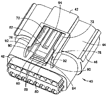
E00183 The main. housing member 46 comprises a mating
electrical connector latch 60. When the electrical
connector 40 is connected to the second electrical
connector 18, the latch 60 is adapted to removably latch
with the latch protrusion 38 of the 'second electrical
connector 18. Referring also to Figs. 4 and'5, the latch'
60 generally comprises a lever arm 70 having a latch
surface 62 at a front and 64 and a user finger contact
surface 66 at a rear end 68, and two deflectable arms 72.
The main housing member 46 is Pxeferab
(00193 ly a one-
piece, member .comprised of .molded plastic or polymer
material. Thus, the latch 60 is preferably integrally
formed with the rest of the main housing member 46. The
front end- i~4 of the lever arm 70 extends into the
receiving area 54. The rear and 68 .of the lever arm 70
extends out of the main housing member 46 at the top, rear
side, of the. main housit member. The deflectable arms'72
at .e located on opposite lateral sides of the lever arm'
'70.
X0020] The deflectable arms 72 comprises first ends 74
which are attached to the, front'. 64 of the. lever arm 70.
The deflectable arms 72 comprises second ends 76 which
are attached to top rails .78 of the main housing member.
6

CA 02559255 2006-09-20
.
46. The deflectable arms 72 extend inward towards each
other and forward towards the front end 64 of the lever
arm-70. The deflectabl4 arms 72 form combined torsion
bars and spring leafs to allow pivoting movement of the
lever. arm 70 re3.ative to the rest of the main housing
member 46. The second ends 76 are located proximate the
middle or center section of the lever arm 7b close to the
rear end 6$. With the present invention, the deflectable
arms 72 provide forward facing latch beams, integral with
the main housing member, to provide a higher ramp force
with the latch protrusion 38 of the mating electrical
connector is for greater audible' click 'and greater
latching strength. Before connection of the seal
retainer 48 to the main housing member 46, the lever arm
70 is substantially free,=floating; supported merely by
connection of the deflectable arms 72 at the front end
64.
[0021] As seen best in Figs. 2 and 3, the seal
retainer 48 comprises a raised portion 80 on* the top side
of the seal retainer. The raised portion. 86 comprises a
front rail 82 and a rear rail 84. The ~ front rail 82 = is
located 'beneath the lever arm 70. More specifically,
when the seal retainer 48 is connected to the main
housing member 46, the bottom surface of the lever arm 70
rests against the top surface of the front rail 82. The
front rail 82 forms a fulcrum rib for the lever arm 70 as
further understood from the description below. .The front
rail 82 is provided on the seal retainer 48 rather than
on the main housing' member 46.. This provides a pivot
feature, provided by the. seal retainer, which allows for
greater mechanical flexibility and a simplified tooling.
The rear. rail 84 comprises a forward proj ectii~g ledge 86
7

CA 02559255 2006-09-20
at its top side. The real rail 84 forms a grip rib as
well as a portion of a latch overstress-protection system
as further described below.
(00221 Ao seen in Fig. 2, the raised.portJon 80 also
comprises two sidewalls 90 located between the front rail
82 and, the rear rail 84. The aidewalls '90 are spaced
from each other to allow free movement of the rear end 68
of the lever arm 70* therebetween. The. sidewalls 9o
provide anti-snag walls, provided by the seal retainer 48
rather than the main housing member 46, to-'allow the
latch button feature'. of the rear end 68 to be closely
protected without the need of complicated tooling; which
would otherwise be needed for manufacturing an equivalent
feature on the main housing 46. Manufacturer of the seal
retainer 46 with the anti-snag sidewalls 90 does not
require complicated tooling.
00231 The rear and 68 of the lever arm 70 comprises
two projections 88. The projections 88 are located
beneath the ledge 86 of the rear rail 84. The
projections 88 are adapted to' contact. the bottom side of
the ledge 86 to prevent overstress of the latch 60 which
could result in permanent deformation, such as if the
rear end 68 was moved to far outward. T.i' provides a
snag overstress feature, provided by engagement of the
seal retainer. and the main housing member, to provide an
easy -to tool, ergonomically friendly, latch overstress
protection.
[00241 When the second electrical connector 18 is
attached to the electrical connector 40, the front of the
housing 30 will extend into. the receiving. area 54 of the
housing 42 The latch protrusion 38 will contact the
8

CA 02559255 2006-09-20
front end 64 of the latch and deflect the front end 64
-outward until the latch protrusion 38 passes by the front
end. During this process, the deflectable arms 72 will
bend to allow the front end 64 to deflect-outward and the
lever arm 70 will pivot on top the front rail 82. After
the latch. protrusion 38 passes by the front and 64, the
front. end 64 will snap back, because of the forces
exerted by the deflected arms 72, to locate the latch
surface 62 behind the latch-protrusion 38.
(0025 As seen best in Fig. 3, the top. of the user
contact 'surface 66 at the rear and 68 of the lever arm 7Q
is normally located above the top surface of the rear
rail 84. In=order to disgonnect the electrical connector
40 from the second electrical connector 18, the-user must
first disconnect the latch 60 from the latch protrusion
38. In order to accomplish this, the user depresses the
user contact section, 66 inward as indicated by arrow 96.
The lever, arm 70 can pivot on the front rail 82 to move
the front end 64 outward away from the rear end of the
latch protrusion 38 as indicated by arrow 98_ As the'
user contact surface 66 is moved inward, the top of the
user contact surface 66 can be moved below the top
surface of the rear rail 84. The top surface of the rear
rail 84 forms a grip rib behind the rear end of the latch
which has a top surface that is located vertically above
the rear end of the latch only when the rear end 68 of
the latch is depressed inward. This grip zip formed by
the top surface of the rear rail 84 provides an enhanced
contact surface for the user and makes withdrawal of the
electrical connector 40 from the second electrical
connector 18 easier to accomplish. The grip. rib,
provided by the seal retainer 48 rather than the main
9

CA 02559255 2011-12-23
housing member 46, allows superior grip for connector
separatism.
[0026] In the embodiment shown in Fig. 2, the top rails 78
of the main housing member 46 forms side slots 92 which are
adapted to receive outer sides of a connector position
assurance (CPA) member (not shown). The main housing member 46,
thus, provides a channel for a CPA member above the latch 60.
The CPA member can be slid into the main housing member 46
above the latch 60 and into a location 94 above the lever arm
70 to prevent the latch 60 from becoming accidentally
disengaged from the latch protrusion 38. However, in an
alternate embodiment, a CPA member might not be provided. The
rear end 68 of the lever arm 70 can be located in a reward path
of the CPA member to prevent inadvertent removal of the CPA
member from the electrical connector 40. The rear end 68
would need to be depressed during rearward movement of the CPA
member to allow the CPA member to be removed from the main
housing member 46.
[0027] It should be understood that the foregoing description
is only illustrative of the invention. Various alternatives and
modifications can be devised by those skilled in the art without
departing from the invention.

Representative Drawing
A single figure which represents the drawing illustrating the invention.
Administrative Status

2024-08-01:As part of the Next Generation Patents (NGP) transition, the Canadian Patents Database (CPD) now contains a more detailed Event History, which replicates the Event Log of our new back-office solution.

Please note that "Inactive:" events refers to events no longer in use in our new back-office solution.

For a clearer understanding of the status of the application/patent presented on this page, the site Disclaimer , as well as the definitions for Patent , Event History , Maintenance Fee  and Payment History  should be consulted.

Event History

Description Date
Time Limit for Reversal Expired 2015-03-11
Letter Sent 2014-03-11
Grant by Issuance 2013-01-08
Inactive: Cover page published 2013-01-07
Amendment After Allowance Requirements Determined Compliant 2012-11-02
Letter Sent 2012-11-02
Amendment After Allowance (AAA) Received 2012-10-10
Pre-grant 2012-10-10
Inactive: Amendment after Allowance Fee Processed 2012-10-10
Inactive: Final fee received 2012-10-10
Notice of Allowance is Issued 2012-04-10
Letter Sent 2012-04-10
Notice of Allowance is Issued 2012-04-10
Inactive: Approved for allowance (AFA) 2012-03-28
Letter Sent 2012-03-08
Amendment Received - Voluntary Amendment 2011-12-23
Inactive: S.30(2) Rules - Examiner requisition 2011-06-27
Amendment Received - Voluntary Amendment 2010-07-26
Letter Sent 2010-04-01
Request for Examination Received 2010-03-10
Request for Examination Requirements Determined Compliant 2010-03-10
All Requirements for Examination Determined Compliant 2010-03-10
Inactive: Cover page published 2007-02-21
Inactive: First IPC assigned 2006-11-02
Inactive: IPC assigned 2006-11-02
Application Received - PCT 2006-10-11
Letter Sent 2006-10-11
Inactive: Notice - National entry - No RFE 2006-10-11
National Entry Requirements Determined Compliant 2006-09-20
Application Published (Open to Public Inspection) 2005-09-23

Abandonment History

There is no abandonment history.

Maintenance Fee

The last payment was received on 2012-03-09

Note : If the full payment has not been received on or before the date indicated, a further fee may be required which may be one of the following

  • the reinstatement fee;
  • the late payment fee; or
  • additional fee to reverse deemed expiry.

Patent fees are adjusted on the 1st of January every year. The amounts above are the current amounts if received by December 31 of the current year.
Please refer to the CIPO Patent Fees web page to see all current fee amounts.

Owners on Record

Note: Records showing the ownership history in alphabetical order.

Current Owners on Record
FCI AUTOMOTIVE HOLDING
Past Owners on Record
FRANKLIN ANTHONY HOLUB
Past Owners that do not appear in the "Owners on Record" listing will appear in other documentation within the application.
Documents

To view selected files, please enter reCAPTCHA code :


To view images, click a link in the Document Description column. To download the documents, select one or more checkboxes in the first column and then click the "Download Selected in PDF format (Zip Archive)" or the "Download Selected as Single PDF" button.

List of published and non-published patent-specific documents on the CPD .

If you have any difficulty accessing content, you can call the Client Service Centre at 1-866-997-1936 or send them an e-mail at CIPO Client Service Centre.


Document
Description 
Date
(yyyy-mm-dd) 
Number of pages   Size of Image (KB) 
Description 2006-09-19 10 535
Abstract 2006-09-19 1 31
Drawings 2006-09-19 4 148
Claims 2006-09-19 5 216
Representative drawing 2007-02-20 1 22
Abstract 2006-09-20 2 74
Description 2011-12-22 10 530
Claims 2011-12-22 8 407
Claims 2012-10-09 8 389
Representative drawing 2012-12-11 1 19
Notice of National Entry 2006-10-10 1 192
Courtesy - Certificate of registration (related document(s)) 2006-10-10 1 105
Reminder of maintenance fee due 2006-11-14 1 112
Reminder - Request for Examination 2009-11-15 1 118
Acknowledgement of Request for Examination 2010-03-31 1 179
Commissioner's Notice - Application Found Allowable 2012-04-09 1 163
Maintenance Fee Notice 2014-04-21 1 170
Fees 2007-01-23 1 28
Fees 2008-03-05 1 31
Fees 2009-01-19 1 32
Correspondence 2012-10-09 22 954