Note: Descriptions are shown in the official language in which they were submitted.
CA 02559469 2006-09-12
EXPANSION ACTIVATED ANTI-ROTATION DEVICE
BACKGROUND OF THE INVENTION
Field of the Invention
Embodiments of the invention generally relate to tubular connections.
Description of the Related Art
In order to access hydrocarbons in subsurface formations, it is typically
necessary to drill a bore into the earth. The process of drilling a borehole
and of
subsequently completing the borehole in order to form a wellbore requires the
use of
various tubular strings. These tubular members are typically run downhole
where the
mechanical and seal integrity of the jointed connections are critically
important in the
original make-up of the tubular members, during expansion of the tubular
members,
and after expansion of the tubular members.
Typically, simple male to female threaded connections connect multiple tubular
members end-to-end. The male end is generally referred to as a pin, and the
female
end as a box. The tubular members are connected, or "made-up," by transmitting
torque against one of the tubular members while the other tubular member is
typically
held stationary. Transmitting torque in a single direction corresponding with
connection
make-up tightens the threaded joint in order to establish the seal integrity
and lock in
the applied torque.
When running tubular members, there is sometimes a requirement to run jointed
tubular members that will later be expanded by various types of expansion
mechanisms. The most basic type of expander tool employs a simple cone-shaped
body, which is typically run into a wellbore to the tubular member that is to
be
expanded. The expander tool is then forced through the tubular members to be
expanded by pushing or pulling on the working string from the surface and/or
applying
fluid pressure on one side of the cone. Alternatively, rotary expander tools
can employ
one or more rows of compliant rollers that are urged outwardly from a body of
the
expander tool in order to engage and to expand the surrounding tubular member.
The
1
CA 02559469 2006-09-12
rotary expander tool is rotated downhole so that the actuated rollers can act
against the
inner surface of the tubular member to be expanded in order to expand the
tubular body
circumferentially. Radial expander tools are described in U.S. Patent
6,457,532, issued
to Simpson et al., and that patent is incorporated herein by reference in its
entirety.
Expanding tubular members that use the same threaded connections as
employed with conventional oil-field tubular members proves to be problematic.
First,
changes in geometry of the connection once expanded can reduce the locked in
torque
and the tensile capacity of the connection due to loss of intimate contact
between the
threads when the locked in torque is reduced. Additionally, a threaded
connection
potentially turns and loosens during expansion due to rotation and frictional
contact of a
rotary expansion tool. For example, left hand threaded box by pin connections
rotate in
the clockwise direction when expanded with the rotary expansion tool in the
clockwise
direction. This transferred rotation potentially slackens off the threaded
connections
within a multiple joint tubular string being expanded that is differentially
stuck at the
bottom when expansion takes place top down. On the other hand, transferred
clockwise rotation from the rotary expansion tool potentially loosens the
threaded
connection regardless of differential sticking when expansion occurs in a
bottom to top
direction. Addition of right hand threaded connections for use in the tubular
string to
help remedy these problems related to undoing of the connection during
expansion only
present further issues such as inventory concerns and specialized equipment
requirements.
Therefore, a need exists for an improved tubular connection that is capable of
being made-up and broken-out numerous times prior to expansion while
torsionally
locking itself upon being expanded.
SUMMARY OF THE INVENTION
Embodiments of the invention generally relate to threaded tubular ends having
a
slot cut across a thread at a location along the circumference of the thread.
A
connection according to embodiments of the invention includes those formed
between
2
CA 02559469 2006-09-12
two tubular members that have the slot disposed in either or both of a pin or
box end of
the tubular members. The slots represent no impediment to the make-up or break-
out
of a box by pin connection prior to expansion. During expansion of the
connection, the
threads of either the box or pin end are forced via plastic flow into the slot
in the
corresponding thread. This results in locking the connection and preventing
relative
rotation between the two tubular members, which could otherwise loosen the
connection.
BRIEF DESCRIPTION OF THE DRAWINGS
So that the manner in which the above recited features of the present
invention
can be understood in detail, a more particular description of the invention,
briefly
summarized above, may be had by reference to embodiments, some of which are
illustrated in the appended drawings. It is to be noted, however, that the
appended
drawings illustrate only typical embodiments of this invention and are
therefore not to
be considered limiting of its scope, for the invention may admit to other
equally effective
embodiments.
Figure 1 is a side view of a portion of a tubular member having a pin end with
an
axial slot extending across threads formed on the pin end.
Figure 2 is a cross sectional view of a portion of a tubular member having a
box
end with an axial slot extending across threads formed inside the box end.
Figure 3 is a partial cross sectional view of a connection between two tubular
members with a box end cut away to illustrate a random pattern of slots in
threads
circumscribing a pin end.
Figure 4 is an elevation view schematically showing tubular members within a
borehole and a representative expander tool at a connection according to
aspects of
the invention between two of the tubular members.
3
CA 02559469 2006-09-12
DETAILED DESCRIPTION
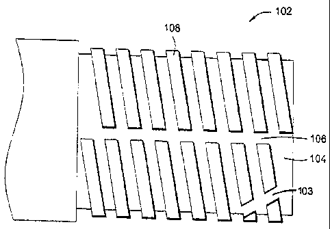
Figure 1 shows a portion of a tubular member 102 having a pin end 104 with an
axial slot 106 extending across a helical thread 108 formed on the pin end
104. The
slot 106 interrupts the thread 108 at the same circumferential point along the
entire
axial length of the pin end 104. For some embodiments, the slot 106 extends
across
only a portion of the pin end 104 such that at least some individual turns of
the thread
108 are continuous through the 360° of one turn. The slot 106
preferably extends from
the crest of the thread 108 to a depth no greater than the root of the thread
108. In
general, any standard pin end can be modified by cutting the slot 106 axially
across the
thread 108.
As with other embodiments described herein, multiple slots may be spaced
around the circumference of the thread 108. For example, both the slot 106 and
an
additional slot 103 interrupt the thread 108 within a single 360° turn
of the thread 108.
The slots 103, 106 may be parallel or non-parallel to one another. The
additional slot
103 can extend across only a portion of the pin end 104 as shown or can extend
across
the entire axial length of the pin end 104. Additionally, the size and shape
of the slots)
can vary. For example, the slots) can be at an angle or curved. Furthermore,
the slots
described herein represent no impediment to the make-up or break-out of a box
by pin
connection prior to expansion. Specifically, the thread continues as a normal
thread on
each side of the slot even though the thread is not continuous due to the
slot.
Figure 2 illustrates a portion of a tubular member 202 having a box end 204
with
an axial slot 206 extending across threads 208 formed inside the box end 204.
The slot
206 in the box end 204 serves a similar function and may be modified in a
similar
manner as the slot 106 in the pin end 104. Connections according to
embodiments of
the invention include those formed between tubular members that have the slot
disposed in either or both of the pin or box ends.
Figure 3 shows a connection 360 between a first tubular member 301 and a
second tubular member 302 with a box end 304 of the second tubular member 302
cut
away to illustrate a random pattern of a slot 306 disposed along a thread 308
4
CA 02559469 2006-09-12
circumscribing a pin end 303 of the first tubular member 301. The thread 308
of the pin
end 303 mates with a corresponding thread 309 of the box end 304. The slot 306
cuts
through individual turns of the thread 308 at various locations around the
circumference
of the pin end 303. In contrast to the embodiment shown in Figure 1 where the
slot 106
is straight, the slot 306 interrupts the thread 308 at different
circumferential points along
the axial length of the pin end 303. Again, the random pattern can be applied
to a slot
(not shown) in the corresponding thread 309 of the box end 304 as an
alternative to or
in combination with the slot 306 in the pin end 303 without departing from the
scope of
the invention.
Figure 4 illustrates embodiments of the invention in use within a wellbore 10.
Accordingly, Figure 4 shows a representative rig 2, a ground surface 6, a
formation 4, a
drill string or running string 8, a first tubular member 101, a second tubular
member
201, a representative expander tool 40 comprising a body 42 and an extendable
member 45 or roller, a bore 400 running through the tubular members, and a
connection 60 or joint between the first tubular member 101 and the second
tubular
member 201. in operation, the first tubular member 101 and the second tubular
member 201 are mated together at the surface 6 according to normal stab-in and
threading procedures. The stab-in procedures can be preformed with tubular
members
arranged in a pin up and a box down configuration or a configuration with the
pin down
and the box up.
After run-in, the tubular members can be expanded from within by any method
known to those skilled in the art. The expansion process can be run in any
axial and/or
rotational direction within the tubular members 101, 201 without risk of the
connection
rotating and loosening since the connection 60 becomes torsionally locked
after being
2~ expanded as desc~ ibed below. The running string 8 witty ao expar~iter tool
40 attached
thereto rums thruucdh the bore 400 of the tubular merr~ber5. At a desired
location, an
operator expands the tubular members using the expander tool 40.
When the expander tool 40 reaches the connection 60 between the first tubular
member 101 and the second tubular member 201, an internal wall of a pin end
expands
5
CA 02559469 2006-09-12
into an internal wall of a box end. The connection 60 between the tubular
members
101, 201 is capable of being expanded without losing its mechanical integrity.
The
threads of either the box or pin end are forced via plastic flow into a slot
(e.g., the slots
106, 206 andlor 306 illustrated in Figures 1-3) on the corresponding thread of
the other
end. This results in locking the first and second tubular member 101, 201
together,
thereby preventing rotation across the connection or relative rotation between
the
tubular members 101, 201. Thus, any rotation translated to the tubular members
101,
201 from rotation of the expander tool 40 cannot operate to break-out the
connection 60
once the connection is expanded.
The plastic flow of material into the slots which are disclosed herein upon
expansion of the connection can be caused to occur based at least on
differential
movement between the pin and box ends due to the expansion. For example, the
pin
end tends to elongate while the box end tends to contract when expanding the
connection using rotary expansion methods. For some expansion methods such as
those utilizing a cone or expansion mandrel, both the pin and box end can
shrink with
the relative amount of shrinkage of each end being sufficiently different to
create the
differential movement that at least enhances flow of material into the slots
to lock the
connection.
The expandable tubular members 101, 201 with the connection 60 according to
aspects of the invention can be part of a liner, an open hole or cased hole
patch that is
run-in to a predetermined location or any other type of expandable tubular
string for use
in a well. A method in accordance with embodiments of the invention includes
providing a first end of a first expandable tubular member and a second end of
a
second expandable tubular member, wherein a slot is disposed to intersect a
circumference of a thred~i profile of the first end, the threaiJ prufile
continuing on both
sides of the slot, tfrradding the first and second ends cf the expandable
tubular
members to form a connection therebetween, and expanding the connection with a
radial force. The method can further include running the expandable tubular
members
into a wellbore. The expanding of the connection can include extending
extendable
6
CA 02559469 2006-09-12
members of an expander tool and then rotating and axially translating the
expander tool
across the connection.
While the foregoing is directed to embodiments of the present invention, other
and further embodiments of the invention may be devised without departing from
the
basic scope thereof, and the scope thereof is determined by the claims that
follow.
7