Note: Descriptions are shown in the official language in which they were submitted.
CA 02559920 2006-09-14
WO 2004/086771 PCT/GB2004/001364
A Stereoscopic Display
The present invention relates to a stereoscopic
display and, in particular, an auto-stereoscopic desktop
display incorporating a concave mirror.
Stereoscopic systems attempt to simulate natural
stereoscopic vision in order to provide more life-like
images. In stereoscopic vision, each eye presents the
' brain with a two dimensional image of an object or scene
from slightly different viewpoints. These images are
combined into a single three-dimensional image. In order
to simulate stereoscopic vision, auto-stereoscopic
systems must be arranged so that a two-dimensional image
of the image source is presented separately to each eye.
Each image must be from the viewpoint of the
corresponding eye, so that two images are provided one
for the left eye and one for the right eye of the viewer.
Most existing auto-stereoscopic systems require
viewers to wear some form of special glasses. In one
example, shuttered glasses are used. In this case,
alternate left and right images are rapidly displayed on
a viewing screen and synchronously the right and left
lenses of the viewer glasses are made opaque. Thus, the
viewer is presented with the left image to the left eye
and a right image to the right eye. In another system, a
polarising screen is placed in front of a display screen
and again left and right images are rapidly alternated on
the display. In this case, the orientation of the
polarising filter screen is alternated, for example,
orthogonally in such a manner that one orientation exists
while the left image is displayed and the other when the
right image is displayed. The user wears passive
glasses, each lens of the glasses comprising a polarising
filter one of which is orthogonally rotated relative to
CA 02559920 2006-09-14
WO 2004/086771 PCT/GB2004/001364
-2-
the other. Thus, when configured properly, again the user
is presented with a left image to the left eye and a
right image to the right eye.
A disadvantage of these known systems is that the
viewer has to wear glasses. A further disadvantage is
that they require alternating left and right images to be
displayed. This effectively halves the perceived frame
rate or image refresh rate and can consequently produce a
faint flicker to the user, which can result in viewing
discomfort. Whilst this problem can be overcome by
running the display monitors at double the frame rate
normally used, for example at 12.0Hz, thereby to provide
60Hz per eye, it is not ideal. A yet further
disadvantage is that the glasses effectively act as a
filter to reduce the amount of light reaching the eyes
from the display. This means that both light and colour
loss is experienced. Furthermoreo the inherent
inefficiency of the filters leads to cross-talk, where
some of the image meant for the left eye can reach the
right eye and vice versa. When the display is used for a
prolonged period of time, this can lead to visual
discomfort.
In order to overcome the problems associated with
systems that rely on the use of glasses, various other
stereoscopic arrangements have been proposed. For
example, in another known display a lenticular screen is
used. In this case the need for glasses is avoided
because the screen breaks up the original image into a
number of left and right elements. A display of this
type is described in GB 2,185,825 A. A disadvantage of
this is, however, that the actual horizontal image
resolution is reduced in proportion to the number of
views presented. Unless head tracking is used to
CA 02559920 2006-09-14
WO 2004/086771 PCT/GB2004/001364
-3-
continuously monitor observer position, and move the
lenticular accordingly, pseudoscopic images may be seen
(right eye sees left eye view and vice versa).
Another stereoscopic system that avoids the need for
the user to wear glasses is described in US 3,447,854.
This discloses a three-dimensional viewer in which a pair
of projectors direct converging left and right image
beams along a co-planar axis onto a beam splitter and
from there towards a concave mirror. The concave mirror
acts as a directional screen and defines two exit pupils
at a viewing position, so that the right and left images
can be simultaneously viewed. However, whilst the image
in this system can be viewed without glasses, it suffers
from distortion problems, and in particular key-stoning
effects. ~ther similar arrangements are described in US
6,511,182 where a scanning ball lens assembly forms an
image at the focus of a concave mirror in order to
achieve a wide field of view and large viewing pupil
infinity display, and US 6,522,474 where a pair of
concave mirrors is used in a head mounted display system.
US 4,023,223 and US 4,799,763 illustrate the use of a
concave mirror where no projection optics are used, but
instead the concave mirror itself is used to form the
stereo pair.
US 4,799,763 describes yet another stereoscopic
display. This uses a concave mirror to create a real
image projection of two display sources, one for each
eye, such that the final image resides at the radius of
curvature of the mirror. These images can be viewed by a
viewer located at a distance from the screen that is the
same as the radius of curvature of the concave mirror.
This means that the image is in fact viewed at an overall
distance from the concave mirror of about twice its
CA 02559920 2006-09-14
WO 2004/086771 PCT/GB2004/001364
-4-
radius of curvature. A disadvantage of this is that the
viewing area available to the user is relatively small.
Another problem is that because the concave mirror is the
image-forming element; this means that the quality of the
concave mirror surface has a significant impact on the
overall image quality. In practice, to maximise the
viewing area and allow a reasonable degree of head
movement, this means that the concave mirror has to be
relatively large.
Yet another auto-stereoscopic display is described
in US 2003/0025996 A1. This provides a glasses free auto-
stereoscopic viewing environment, in which an image
agglomeration device (IAD) is used to project left and
right eye images onto a concave mirror formed by a vacuum
deformed membrane on a tensioned frame. For the specific
optical arrangement of US 2003/0025996 A1 to work in
practice, both the IAD and the lenses have to be located
at a position that is out of the line of sight of the
viewer, otherwise it would not be possible for the viewer
to see an image on the screen. Although it is not
explicitly stated this means that the IAD cannot lie on
the optical axis of the concave mirror, making the
projection system off axis. Whilst US 2003/0025996 A1
provides a glasses free environment, the system will
suffer from image distortions, both due to the off-axis
nature of the system and optical performance of the
membrane mirror.
As well as the limitations described above, another
problem with many known stereoscopic displays is that the
viewing field is relatively limited. To overcome this
problem, WO 9S/43126 describes a stereoscopic system in
which the image projection system can be moved in
response to movement of a viewer. More specifically, WO
CA 02559920 2006-09-14
WO 2004/086771 PCT/GB2004/001364
-5-
98/43126 discloses a display generator for generating two
images that together represent a stereoscopic image, and
a tracking mechanism for tracking movement of a viewer's
head. The tracking mechanism is connected to a
controller, which is able to control movement of the
display generator. In the event that the viewer's head
moves, this is detected by the tracking mechanism, which
sends a signal to the controller. The controller then
causes the display generator to moue so that the image
presented on the concave screen moves with the viewer.
Whilst this arrangement allows the viewer a reasonable
degree of freedom and avoids the need for glasses, it
suffers from various disadvantages. Most notably, in
order to ensure that the viewer can always see a good
image, the image generator has to be moved. A
disadvantage of this is that a relatively large space
envelope is needed to accommodate this. Another display
that includes a tracking mechanism is described in the
article "Head Tracking Stereoscopic Display'° by Schwartz
CH2239-2/85/141 1985 IEEE. In this case, however, the
entire display, including the projection system and the
screen tracks movement of the viewer's head.
An obj ect of the present invention is to provide an
improved stereoscopic display, and in particular a
display that avoids the need to wear glasses, whilst
providing an improved viewing experience for the user.
According to a first aspect of the invention, there
is provided a substantially on-axis stereoscopic system
comprising: a concave mirror; a focusing element for
focusing both of a first image and a second image towards
the concave mirror, and a beam splitter between the
mirror and the focusing element for directing light from
the focusing element substantially along the optical axis
CA 02559920 2006-09-14
WO 2004/086771 PCT/GB2004/001364
-6-
of the mirror whilst allowing light reflected from the
mirror to be transmitted therethrough.
By using a single focusing element, preferably a
single lens, to focus both of the first and second images
onto the screen, image quality can be dramatically
improved. Using a single lens on-axis projection system
eliminates keystoning, negating the need for electronic
or optical correction. Since left and right eye image
planes are not tilted with respect to each other there
can be perfect stereo registration of images, and so
image quality can be improved. Those skilled in the art
will appreciate that a suitable lens system can be
carefully chosen, or designed, for projection of first
and second images such that no image movement occurs when
the observer moves within the system exit pupil.
A plurality of focusing elements may be used, each
being provided for focusing both of the first and second
images towards the concave mirror. The plurality of
focusing elements may be stacked along a single optical
axis.
The first and second images may be provided in
different planes. The first and second images may be
provided in planes that are symmetrically placed relative
to an axis. The first and second images may be provided
in substantially parallel planes. Alternatively, first
and second images may be provided in substantially
perpendicular planes.
According to another aspect of the invention, there
is provided a stereoscopic system comprising: a concave
mirror; first and second focusing means for focusing
first and second images towards the screen, the first
image being positioned so that its centre is offset from
an optical axis of the first focusing means and the
CA 02559920 2006-09-14
WO 2004/086771 PCT/GB2004/001364
_7_
second image being positioned so that its centre is
offset from the optical axis of the second focusing
means, and a beam splitter between the mirror and the
first and second focusing means for directing light from
the first and second focusing means towards the mirror
whilst allowing light reflected from the mirror to be
transmitted therethrough.
Preferably, each of the first and second images is
offset by an amount so that each of the first and second
image beams converge towards a geometric axis of the
first and second focusing elements. Preferably, the
geometric axis of the first and second focusing elements
is aligned with the optical axis of the conoave mirror,
so that the first and second images eventually converge
on the optical axis of the concave mirror. ~y offsetting
the first and second images relative to the first and
second focussing means, so that each of the first and
second image beams converge on the optical axis of the
optical element, effects such as keystoning and image
tilt oan be reduced. In a preferred embodiment, flat
field distortion free projection lenses would be used
with their optical axes parallel to the optioal axis of
the oonoave mirror. Irk another embodiment each projection
system is tilted towards the geometric centre of the
mirror. In this case, in order to maintain focus across
the field, the Schiempflug condition should be fulfilled.
The first and second focusing means may be adapted
to focus the first and second images in a viewing plane
that is on or in front of or behind the optical element.
The first image source may be provided in a plane
that is parallel to the optical axis of th.e first
focusing means. In this case, the projection system may
further comprise a reflector, such as a flat mirror,
CA 02559920 2006-09-14
WO 2004/086771 PCT/GB2004/001364
_g_
positioned so as to reflect light from the first image
source into the first focusing means. The second image
source may also be provided in a plane that is
substantially parallel to the optical axis of the
focusing means. In this case, the projection system may
further comprise a second reflector, such as a flat
mirror, positioned, so as to reflect light from the
second image source into the second focusing means.
According to another aspect of the invention, there
is provided a stereoscopic system comprising a movable
optical element, preferably a concave mirror, that acts
as a directional screen and generates a system exit
pupil; a projection system for projecting first and
second images towards the optical element, the first and
second images being provided from first and second image
sourcesa a tracking system for tracking movement of a
viewer, and a drive for causing movement of the optical
element in response to movement detected by the tracking
system.
By moving the optical element in response to signals
from the tracking mechanism, the position of the element
can follow that of the viewer, so that an optimum view of
the images can be maintained. This simple solution
avoids the need for special glasses, without compromising
the projection system that provides the images, and
whilst providing an apparently larger viewing window for
the user.
Various aspects of the invention will now be
described by way of example only and with reference to
the accompanying drawings, of which:
Figure 1 is a schematic diagram of a first auto-
stereoscopic system;
CA 02559920 2006-09-14
WO 2004/086771 PCT/GB2004/001364
-9-
Figures 2(a) and (b) are schematic views of two
image source and lens systems for use in the arrangement
of Figure 1;
Figure 3 is a diagrammatic representation of another
image source and lens system for use in the auto
stereoscopic system of Figure 1;
Figure 4 is a diagrammatic representation of yet
another image source and lens system for use in the auto-
stereoscopic system of Figure 1;
Figure 5(a) is a diagrammatic representation of yet
still another image source and lens system for use in the
auto-stereoscopic system of Figure 1, and Figure 5(b) is
a representation of an alternative lens arrangement for
use in the system of Figure 5(a);
Figure G is a schematic view of a comparison between
the vertical head movement that is available in the dual
lens arrangement of Figures 5 and 4 and that of the
single lens arrangement of Figure 5;
Figures 7 (a) to (d) are diagrammatic representations
of a variation of the image and lens system of Figure 5,
and
Figure 8 is a diagrammatic representation of a
modified version of the display of Figure 1.
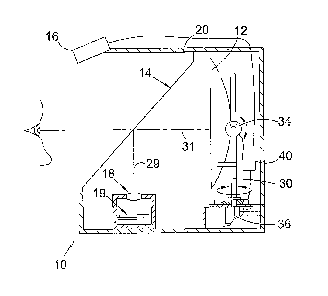
Figure 1 shows an auto-stereoscopic system 10 that
includes four basic sub-systems: a concave mirror 12 that
acts as a directional screen; a beam splitter 14; a head
tracking device 16 and an image projection sub-system 18
for projecting images onto the concave mirror. Each of
the mirror 12, the beam splitter 14 and the image
projection system 18 is included in a housing 20. The
concave mirror 12 is used as a directional screen and to
produce an exit pupil that is formed as a real image of
the projection lens assembly 18. The observer looks
CA 02559920 2006-09-14
WO 2004/086771 PCT/GB2004/001364
-10-
through this exit pupil to see the image in three
dimensions, without the use of glasses.
The concave mirror 12 is located towards the rear of
the housing 20, with the beam splatter 14 positioned in
front of it. The beam splatter 14 is adapted so that in
use at least some of the light transmitted from the image
projection sub-system 18 is reflected from its surface
and onto the concave surface of the mirror 12. The
transmission/reflection properties of the beam sputter
allow at least some of the light reflected from the
concave surface 12 to be transmitted through the beam
splatter so that images can be viewed by the viewer, who
in practice is located on the opposing side of the beam
splatter from the mirror 12. As will be appreciated,
varying the transmission/ reflection properties of the
beam splatter determines the brightness of the images
that reach the user~s eyes. Ideally, the beam splatter
should have a transmission/reflection ratio of 50:50. As
an example, a pellicle beam splatter may be used.
Light is directed towards the beam splatter lay the
image projection sub-system 18. This may have single or
multiple lenses. A specific example of a multiple lens
system is shown in Figure 2(a). This has two identical
lenses 22 and 24, one of these lenses 22 being positioned
alcove a right hand image source 26 and the other 24 being
positioned above a left hand image source 28. As shown,
the lenses 22 and 24 lie in the same plane, although this
may be changed by, for example, tilting the lenses as and
when desired. The lenses 22 and 24 are spaced apart by
an amount that corresponds to the average inter-ocular
spacing of about 63mm, so that the real images of the
projection lenses projected by the concave mirror 12 are
optically at the correct position to enter the left and
CA 02559920 2006-09-14
WO 2004/086771 PCT/GB2004/001364
-11-
right eye of the viewer, i.e. separated by an amount of
the order of 63mm.
The source images 26 and 28 could be provided side
by side on a single display or provided on two separate
displays. In either case, the first image 26 is
positioned so that its centre is offset from an optical
axis of the first lens 22. Likewise, the second image 28
is positioned so that its centre is offset from an
optical axis of the second lens. The projection lens
10~ assembly 18 is itself positioned so that the geometric
axis 29, that is the mid-point, of the first and second
lenses is aligned with the optical axis of the concave
mirror 12. Because of this, the first and second image
beams eventually converge on the optical axis 31 of the
concave mirror 12. By arranging the projection lens
system 18 as described previously distortion effects can
be reduced.
As an alternative example, Figure 2(b) shows a
single lens projection system, which has a single lens 25
positioned above and extending over each of the right and
left hand image sources 26 and 28 respectively. The
single lens 25 is adapted to focus light from each of the
image sources to produce images that are spaced apart by
an amount that corresponds to the average inter-ocular
spacing of about 63mm. As for the arrangement of Figure
2 (a) , the source images 26 and 28 could be provided side
by side on a single display or provided on two separate
displays. The projection system of Figure 2(b) is
positioned so that the optical axis 27 of the projection
lens 25 is aligned with the optical axis 31 of the
concave mirror 12, and the lens 25 is located at the
radius of curvature of the mirror 12.
When the projection system 18 of Figure 2 (b) is
CA 02559920 2006-09-14
WO 2004/086771 PCT/GB2004/001364
-12-
positioned in the display of Figure 1 as described above,
the projection part of the display is essentially on-
axis. This is because the optical axis ~7 of the
projection system is substantially aligned with the
optical axis 31 of the concave mirror 12, so that light
transmitted onto the beam splitter from the projection
system is directed along the optical axis of the mirror,
ensuring that the projected image quality is optimised.
Since the viewing position is ideally along the optical
axis 31 of the mirror 12, this means that the viewing
position for the configuration of Figure 1 is also on
axis . It should be noted, however, that were the concave
mirror 12 of Figure 1 to be moved from the position
sh~wn, this would not always be the case. This will be
discussed in more detail later.
The location of the lens of the image projection
sub-system 1~ determines the position ~f the image that
is formed. In a preferred example, the concave mirror 12
is located substantially at the image plane of each lens.
~0 In this case~ the image is formed on the plane of the
concave mirror 1~. Alternatively, the position or focal
length of the lenses oould be changed so that the image
is formed in front of or behind the mirror. Where lens
position is changed from the preferred position at the
mirror's radius of curvature, the resulting viewing
position will also change. This could be advantageous
where enlarged viewing windows are desired, but where
only small diameter projection optics are available.
Similarly, increased field of view and feeling of
immersion could be achieved where the pupil is de-
magnified and the observer is positioned closer to the
mirror. Optically, however, the optimum position for the
projection system is for the pupil to be located at the
CA 02559920 2006-09-14
WO 2004/086771 PCT/GB2004/001364
-13-
radius of curvature of the mirror. Figure 1 illustrates
the concave mirror 12 situated in front of the user,
however, it will be appreciated that the mirror 12 could
be located above, below or to either side of its current
position by simply altering the angle of the beamsplitter
and location of the projection assembly.
The concave mirror 12 is mounted on a kinematic
support that has a primary support frame 30 that allows
it to be rotated and a secondary support frame 32 that
allows it to be tilted. Connected to the kinematic
support is a drive system. This drive system includes,
but is not restricted to, servomotors. One of these
motors 34 is connected via a transmission system to the
axes of the primary support frame and the other 36 is
connected to the axes of the secondary support frame.
The motors 34 and 36 are operable to steer the mirror 12
in two axes, i.e. pan and tilt, preferably about its
geometric axis/centre. Connected to the motors 34 and 36
is a control system 40 that is operable to send control
commands t~ cause activation of the motors, and thereby
movement of the mirror 12.
Connected to the control system 40 for the kinematic
drive system is a tracking device 16 that is operable to
monitor the position of a viewer's head and feed back
signals indicative of this movement to the control system
40. The head tracking may be implemented in various ways.
For example, a reflective target may be provided on the
system user, which target would then be tracked by an
infrared transmitter- receiver system. Alternatively, a
camera system coupled with image analysis software could
track the position of a user's eye. In practice, the
latter is preferred because it does not require the user
to wear an artificial target. The tracking device of
CA 02559920 2006-09-14
WO 2004/086771 PCT/GB2004/001364
-14-
Figure 1 is shown mounted on a front portion of the
housing 20. It will be appreciated, however, that it
could be located anywhere, provided there is a clear line
of sight to the user.
Tracking is implemented using the control system 40.
The position of, for example, the user's eyes is acquired
by the head tracker 16. This position data is fed back
from the tracker to the control system 40 and used as an
input to a simple computer algorithm in the control
system 40 that produces output information to drive the
servo-motors 34 and 36, thereby to ensure that an optimum
view of the image is presented to the user as he or she
moves around in space. Hence, in the event that the
viewer moves his head to the left, this is detected by
the tracker 16 and a control signal is sent to the motors
34 and 36 to cause the concave mirror 12 to be rotated in
the same direction. Likewise, if the viewer were to move
their head up slightly, a control signal would be sent to
the servomotors 34 and 36 to cause the concave mirror 12
to be tilted upwards. In this way, the image is moved in
a manner that corresponds to m~vement of the viewer's
head, increasing the permissible head movement in the
system. This facility also would allow the image to be
slaved to the user's head position such that motion
parallax could be introduced. The combination of concave
mirror 12, head tracking sensor, feedback control, and
kinematic structure of the mirror support frame improves
the comfort and ease of use of the system for a user. In
particular, by providing the tracking mechanism, the user
can move his or her head within reasonable limits while
continuing to observe the stereo image. Hence, an
enlarged viewing field is provided.
Figure 3 shows an alternative image projection sub-
CA 02559920 2006-09-14
WO 2004/086771 PCT/GB2004/001364
-I S-
system 42 for use in the auto-stereoscopic system of
Figure 1. As before, the projection lens system 46 has a
first and a second lens 44 and 46 respectively for
directing light into the right and left eyes of the
viewer. The images are provided on two orthogonal
displays, Display A and Display B. Display A is
positioned so that it lies i~n a plane that is
substantially parallel to the optical axis of the first
lens 44 of the projection lens system 42. In order to
ensure that the image from Display A is projected into
the first lens 44, a flat mirror 48 is provided directly
facing the display and along the optical axis of the
first lens 44. As shown in Figure 3, the mirror is
aligned at an angle of 45° relative to the optical axis,
but as will be appreciated this could be varied as and
when desired. The image of Display A is positioned so
that its centre 43 is offset from an optical axis 45 of
the first lens 44. Display B is positioned so that it
directly faces the second lens 46 and lies in a plane
that is substantially perpendicular to the optical axis
47 of that second lens 4~. The image of Display B is
positioned so that its centre 51 is offset from the
optical axis 47 of the second lens 46.
When the projection system of Figure 3 is used in
the display of Figure 1, it is positioned so that the
geometric axis 49 of the first and second lenses 44 and
46 respectively is aligned with the optical axis 31 of
the concave mirror 12. Light from Display A falls on the
flat mirror 48 and is reflected into the first lens 44 of
the projection lens system, where it is projected towards
the beam splitter. Light from Display B is transmitted
directly into the second lens 46, where it is projected
towards the beam splitter. Because of the offset
CA 02559920 2006-09-14
WO 2004/086771 PCT/GB2004/001364
-16-
positions of Displays A and B and the relative alignments
~of the geometric axis of the projection system and the
optical axis of the concave mirror, the image beams
eventually converge on the optical axis of the concave
mirror.
Figure 4 shows yet another image projection sub-
system 50 that can be used in the system of Figure 1. As
before, the optical arrangement includes a projection
lens system 52 including first and second lenses 54 and
56 respectively for directing light into the right and
left eyes. The image sources, Display C and Display D,
are located behind the lenses 54 and 56. Directly facing
Display C is a large, flat surface mirror 58. As shown,
this is positioned at an angle of 45° relative to a line
perpendicular to Display C. It will be appreciated,
however, that this could be varied as desired. This
mirror 58 faces inward towards Display C and is sued and
positioned so that the entire image on Display C can be
projected onto it. Likewise, a similar flat mirror 60 is
positioned opposite Display D~ with this mirror facing
inward towards Display D. These large mirrors 58 and 60
have reflecting surfaces that are symmetrically placed on
either side of the projection lens system 52. As shown,
the mirrors 58 and 60 are substantially perpendicular,
but this is not essential in all implementations. As for
the system of Figure 3, the geometric centre of Display C
is offset from the optical centre 57 of the first lens
54, and the geometric centre of Display D is offset from
the optical centre 59 of the second lens 56, so that the
images converge at the image plane.
Also provided in the system of Figure 4 are two
smaller flat mirrors 62 and 64 that are positioned on an
axis that passes between the first and second lenses 54
CA 02559920 2006-09-14
WO 2004/086771 PCT/GB2004/001364
-17-
and 56 respectively and at 45° relative thereto. It will
be appreciated, however, that this specific angle of
alignment is not essential and may be varied to meet
particular design criteria. In the configurations shown,
with the displays lying perpendicular to the geometric
axis 61, each of the smaller mirrors 62 and 64 is
parallel to the corresponding one of the larger mirrors
58 and 60 respectively and is positioned so that its
reflecting surface faces that of the larger mirror. The
smaller mirrors 62 and 64 are positioned to reflect light
transmitted from the large mirrors 58 and 60 into the
projection lenses 54 and 56.
When the arrangement of Figure 4 is used in the
display of Figure 1, it is positioned so that the
geometric axis 61 of the first and second lenses is
aligned with the optical axis 31 of the concave mirror
12. Light from each display C and D travels towards the
corresponding one of the larger mirrors 58 and 60, where
it is reflected onto the corresponding one of the smaller
mirrors 62 and 64 and from there into one of the lenses
54 and 56 of the projection lens system 52. These beams
are then projected towards the beam splatters, where they
are directed towards the concave mirror, so that they
eventually converge on the optical axis 31 thereof. As
will be appreciated, the degree of magnification of the
image in the system of Figure 4 is dependent on the
distance of the source displays C and D from the lens
assembly and the optical power of that assembly. The
focal length of the lenses is selected according to the
overall size of the system.
The projection lens system of Figure 4 has been
included in the arrangement of Figure 1. Using a concave
mirror having a 560mm aperture with a 400mm focal length
CA 02559920 2006-09-14
WO 2004/086771 PCT/GB2004/001364
-1 ~-
and a lens combination consisting of two pairs of lenses
of 800mm and 600mm focal length respectively, a highly
effective stereoscopic system can be provided.
The projection systems described with reference to
Figures 3 and 4 use two focusing elements, each
associated with one of the images. However, in any of
these a single focusing element could be used to focus
both of the right and left images, as shown in Figure
5(a). Alternatively, a plurality of such elements could
be used, these being stacked along a single optical axis,
as shown in Figure 5 (b) . In either case, a single large
exit pupil is formed, through which the observer looks,
with the left eye using the left half of the lens and the
right eye using the right half of the lens. In the
example shown in Figure 5(a), the single focusing element
is a lens. Light from each of the right and left images
is focused through a right and left part respectively of
the lens. As outlined previously, using a single lens to
focus both of the first and second images towards the
screen can improve image quality. Further improvements
can be gained by ensuring that the optical axis of the
lens is aligned with that of the concave mirror, thereby
to provide an on-axis system. Additionally, greater
vertical head movement within the pupil can be achieved
when a single lens of diameter D is used compared with
two lenses of diameter D/2. This is shown in Figure 6.
For a given axial length, both lens systems have
ostensibly the same lateral head movement.
Figure 7(a) shows an isometric view of another,
preferred, embodiment of a stereoscopic display that has
a single lens projection system. As before, the optical
assembly consists of a concave mirror 80, a beamsplitter
82, image sources 84a and 84b, projection lens 86,
CA 02559920 2006-09-14
WO 2004/086771 PCT/GB2004/001364
-19-
folding planar mirrors 88a and 88b forming an apex which
bisects the projection lens 86 and larger planar folding
mirrors 90a and 90b. The concave mirror 80 ~is again used
as a directional screen and to produce an exit pupil that
is formed as a real image of the projection lens 86. The
observer looks through this pupil to see the image,
preferably for example in three dimensions. The folding
mirrors 88a, 88b, 90a and 90b redirect the light from the
image sources 84a and 84b toward the projection lens 86
which sends the light toward the beamsplitter 82 which
redirects some of the light toward the concave mirror 80.
This light is re-directed by the concave mirror 80 toward
the viewer.
In order to produce an ergonomically feasible system
the folding mirrors 88a and 88b, 90a and 90b, the
projection lens 86 together with the image sources 84a
and 84b are at varying angles with respect to each other.
Figure 7(b) shows a side view of these Angles A, B and C
all of which can be varied with respect to the image
sources 84 to minimise the overall size of the optical
assembly by minimising rotation of the image sources 84 .
Figure 7(c) shows the plane of rotation of the image
sources 84a and 84b, as depicted by Angle G, which is
being compensated for. By angling the projection lens 86
slightly out toward the viewer, Angle A of Figure 7(b),
the beamsplitter 82 and concave mirror 80 are pushed
forward which in turn throws the exit pupil further away
from the lower half of the optical assembly. Hence, when
the assembly is provided in a desktop environment, with
the projection optics below the desktop, this means that
leg-room for the viewer can be maximised. Additionally
the concave mirror 80 and the beamsplitter 82 are angled
so that the viewer has a slightly downward gaze when
CA 02559920 2006-09-14
WO 2004/086771 PCT/GB2004/001364
-20-
viewing the image so as to comply with ergonomic ideals
when viewing visual display units.
The main purpose of the planar mirrors 88a and 88b
is to allow image sources of virtually limitless size to
be utilised. The planar mirrors create virtual images of
the image sources 84a and 84b, which can overlap each
other. Other systems such as described in US 3,447,854
are limited in the size of image sources they can use due
to the projectors being side by side therefore
necessitating the requirement for these projectors to be
small enough in size so as to match the inter-ocular
spacing of the human eyes. Otherwise the image sources
would have to overlap each other physically, which is
impossible in practice. If the projectors did not overlap
the inter-ocular spacing of the images would be so wide
that only one eye at a time would be able to observe an
image. Thus, no 3D image would be viewable.
The front elevation of the preferred embodiment,
Figure 7(d), depicts Angles D, E and F which again can
~0 all be varied with respect to each other lay way of
maximising field of view of the image sources whilst
maintaining a compact optical assembly. Angle D is
critical in ensuring that the entire field of view of the
image sources 84a and 84b can be observed by the viewer
whilst maintaining the maximum amount of head movement
within the exit pupil. Preferably this angle should be
less than 90°, except for very small image sources, so
that the full field of view and maximum head movement can
be maintained.
Due to there being a single lens used in the
configuration of Figure 6 a common optical axis is
maintained for all components resulting in a fully on-
axis optical assembly. Even if head tracking were to be
CA 02559920 2006-09-14
WO 2004/086771 PCT/GB2004/001364
-21-
employed, by manipulation of the concave mirror 80, due
to minimal requirements for the rotation of the mirror
the system would still be substantially on-axis. In this
case, for a viewing distance of, say, 900mm typically the
optical mirror could be rotated by say up to 5 degrees,
without a significant impact on image quality. This
would give a lateral head movement of about 10-l5cm
either side of the optical axis. Of course, it will be
appreciated that the angle by which the mirror can be
moved to accommodate the same degree of head movement
would vary depending on how close the user is to the
screen. To accommodate the same amount of head movement,
when the user is relatively closer to the screen the
angle of rotation of the mirror will be greater, whereas
when the user is relatively further from the screen, the
angle of rotation of the mirror would be lower.
Figure 8 shows an on-axis system that is similar to
that of Figures 1 and 7, except that the position of the
projection lenses is variable. This means that the
'~0 location of the image plane can be varied, s~ that the
image can be made to appear in front of, on, or behind
the plane of the concave mirror. This is a significant
improvement over existing systems because it allows the
user's eyes to more naturally accommodate and converge on
the object of interest. Most conventional. 3-D displays
are limited by the location of the screen. To make the
image appear to come out of the screen of such a
conventional display, the images are moved to each side
of the screen so that the viewer's eyes have to cross
slightly in order to view them. Crossing the eyes in
this way causes the convergence point to lie out in front
of the screen, and so the image appears to lie in this
plane. This provides a 3-D effect. However, the focus
CA 02559920 2006-09-14
WO 2004/086771 PCT/GB2004/001364
-22-
point is still on the screen and so there is a mismatch
between the actual focal plane and the location of the
image. This can cause the viewer's eyes to strain and so
stimulate headaches and other strain related symptoms.
By allowing the image plane to be moved to a point in
front of the screen, or indeed behind the screen, the
focal point and the position at which the eyes converge
can be more closely matched, so providing a more
comfortable viewing experience. Of course, rather than
moving the lens or lenses, the display could be provided
with a range of interchangeable lenses having different
optical powers, each of which could be used in the
projection system as and when desired, or a zoom
projection assembly could be used.
All of the systems described above allow a single
viewer to view full stereoscopic images that may comprise
live or recorded video, cine film, still images, or
animated computer graphics and the like. These images
may be provided by various means. For example, micro-
display technologies could be used to provide the images,
such as organic light-emitting displays (OLEDs), liquid
crystal on silicon (LC~S) or high temperature poly
silicon (HTPS) and digital light processing (DLP), in
addition to conventional displays such as CRTs, LCDs,
etc.
A skilled person will appreciate that variations of
the disclosed arrangements are possible without departing
from the invention. For example, in Figure 3, the lenses
44 and 46 are shown as being spaced from the top of the
mirror 48 by a finite amount d. However, ideally the
separation d should be as small as possible and
preferably zero in order to maximise the degree of
lateral head movement for the observer. This is true for
CA 02559920 2006-09-14
WO 2004/086771 PCT/GB2004/001364
-23-
all of the projection sub-systems described herein.
Also, although the display is described as being for use
on a desktop, it could be provided in a dedicated viewing
booth or on a mobile platform. Alternatively, the display
could be miniaturised and provided in a head mountable
unit, so that it could be worn. In addition, where
specific angles are mentioned, it will be appreciated
that these may be varied. Furthermore, the various
systems could include means for electronically correcting
the image to address key-stoning and distortions brought
about by projecting an image onto a curved mirror
surface. Also, whilst in the lens arrangements shown in
Figures 3 and 4 show each projection system, that is both
the right and left image projection systems, being
positioned substantially parallel to the geometric axis
of the mirror 12, in another embodiment each projection
system may be physically tilted towards the geometric
centre of the mirror. In this case, in order to maintain
focus across the field, the Schiempflug condition should
be fulfilled. Accordingly, the above description of the
specific embodiment is made by way of example only and
not for the pure~ses of limitation. It will be clear to
the skilled person that minor modifications may be made
without significant changes to the operation described.