Note: Descriptions are shown in the official language in which they were submitted.
CA 02560211 2006-09-20
REAGENT CONTAINER ASSEMBLY AND ANALYZER COMPRISING SUCH
ASSEMBLY
FIELD OF THE INVENTION
The invention concerns a reagent container assembly adapted
for being installed in a substantially cylindrical cavity of
an analyzer.
The invention further concerns an analyzer comprising such a
reagent container assembly.
BACKGROUND OF THE INVENTION
In automatic analyzers, and in particular in clinical
chemistry analyzers, it is convenient to have a reagent
container assembly which contains a plurality of reagent
containers suitable for carrying out various analysis and
which can be easily handled and installed in the analyzer.
For proper and reliable operation of the analyzer it is
indispensable to avoid using the wrong reagent when
performing an analysis. It is therefore important to make
sure that the proper reagents .are loaded into the reagent
container assembly installed i:n the analyzer and that the
reagent management system of the analyzer has information
that identifies those reagents. For this purpose, the
individual reagent containers ,~s well as the reagent
container assemblies are identified e.g. by means of barcode
labels for the purpose of automatic identification and
control by the reagent management system of the analyzer.
In spite of the above actions and steps for ensuring proper
identification and control of the reagents being used, it
d
CA 02560211 2006-09-20
- 2 -
cannot be fully excluded that reagent containers installed
in the analyzer are manually taken out and replaced by
another reagent and that the reagent management system of
the analyzer may fail to detect errors that may occur during
such manipulations.
The problematic situation just mentioned is particularly
prone to occur when the reagent container assemblies are
manually handled for installing them into the analyzer and
removing them from the analyzer when necessary. In larger
analyzer systems, the risk of errors in handling reagents
can be considerably reduced by an expensive, fully automatic
handling of the regents. Such an approach is however not
possible in case of a low cost, relatively small analyzer
intended to be used in small laboratories or even by medical
doctors in their own laboratories, because in those cases,
in order to reduce the manufacturing costs of the analyzer,
manual handling of the reagent assemblies is indicated.
Nevertheless, also in those cases, it is desirable to reduce
the risk of errors in handling the reagents as far as
possible.
SU~PaRY OF THE INVENTION
A first aim of the invention is to provide a reagent
container assembly which makes possible to avoid the above-
mentioned drawbacks of known reagent container assemblies.
According to one aspect of the inventin there is provided
a reagent container assembly adapted for being installed in
a substantially cylindrical cavity of an analyzer, said
reagent container assembly comprising a housing defining at
least one circular array of chambers, each chamber being
adapted for receiving a reagent container, said housing
CA 02560211 2006-09-20
- 3 -
having an upper opening, a cover for closing said upper
opening of said housing, and locking means arranged within
said housing, said locking means comprising a locking sleeve
and a locking pin, said locking means being.adapted for
locking said cover at all times, thereby preventing rotation
of the cover with respect to the housing, said locking means
being adapted for locking said housing and thereby
preventing rotation of said housing when the reagent
container assembly is removed from its position in said
cavity of the analyzer, and said locking means being further
adapted for cooperating with a bolt arranged at the center
of the bottom of said cavity of the analyzer when the
reagent container assembly is installed in the analyzer,
said housing being unlocked by said cooperation and thereby
allowed to be rotated within said cavity of the analyzer.
A second aim of the invention is to provide an analyzer that
makes possible to avoid the above-mentioned drawbacks of
analyzers known in the prior art.
According to another aspect of the invention there is
provided an automatic analytical apparatus, said apparatus
comprising: (a) a rotatable conveyor for conveying reaction
cuvettes along a.circular path, said conveyor having a first
ring shaped body having a circular array of cavities, each
cavity being adapted for receiving a single reaction
cuvette, and a second ring shaped body having a wall which
extends upwardly form the inner side of said first ring
shaped body, said wall having openings, each of said
openings being adapted for receiving a corresponding
connecting part of a cuvette holder which holds a plurality
of said reaction cuvettes, said second ring shaped body
defining a first chamber within said second ring shaped
body,(b) a bucket arranged in .said first chamber within said
CA 02560211 2006-09-20
- 4 -
second ring shaped body, said bucket having a bottom wall
and side walls that define a second chamber, (c) a reagent
container assembly as defined above, said assembly being
adapted for being positioned in said second chamber, said
reagent container assembly containing a plurality of reagent
containers each of which contains a specific reagent in
liquid form, and (g) conveyor driving means for rotating
said conveyor in a step-wise manner.
In some preferred features the apparatus further comprises:
(a) at least one cuvette array including a plurality of
reaction cuvettes inserted into corresponding cavities of
said first ring shaped body of said conveyor,(b) a sample
tube area located adjacent to ;said conveyor having cavities
each of which is adapted for receiving a sample tube
containing a liquid sample to be analyzed, and (c) an
automatic pipetting device for pipetting samples from said
sample tubes and reagents from said reagent containers into
said reaction cuvettes and thereby forming liquid sample-
reagent-mixtures; or a photometer located adjacent to said
conveyor for carrying out photometric measurements of said
liquid sample-reagent-mixtures contained in said reaction
cuvettes.
The main advantages obtained with a reagent assembly and an
analyzer according to the invention is that the risk of
errors in handling the reagents used is considerably
reduced.
BRIEF DESCRIPTION OF THE DRAWINGS
The subject invention will now be described in terms of its
preferred embodiments with refE:rence to the accompanying
drawings. These embodiments are set forth to aid the
CA 02560211 2006-09-20
- 5 -
understanding of the invention, but are not to be construed
as limiting.
Fig. 1 shows a perspective view of an analyzer according
to the invention.
Fig. 2 shows a perspective view of conveyor 11 in Fig. 1.
Fig. 3 shows a side view of conveyor 11 in Fig. 1.
Fig. 4 shows a perspective view of a cuvette array
according to the invention comprising a cuvette
holder 41 and a plurality of cuvettes 31 of the
type shown in Figures 8-10.
Fig. 5 shows a top plan view of the cuvette array shown
in Fig. 4.
Fig. 6 shows a cross-sectional view taken along a plane
C-C in Fig. 5 of a chamber of cuvette holder 41
and of a cuvette 31 held by that chamber.
Fig. 7 shows a cross-sectional view taken along a plane
D-D in Fig. 5 of a chamber of cuvette holder 41
and of a cuvette 31 :held by that chamber.
Fig. 8 shows a perspective 'view of a reaction cuvette 31
of the type which is preferably used with a
cuvette holder 41 ac~~ording to the invention.
Fig. 9 shows a first side view of reaction cuvette 31 in
Fig. 8.
CA 02560211 2006-09-20
- 6 -
Fig. 10 shows a second side view of reaction cuvette 31 in
Fig. 8.
Fig. 11 shows a perspective 'view of reagent container
assembly 61 when it is removed from the analyzer
shown in Fig. 1.
Fig. 12 shows a top view of -the conveyor part of the
analyzer shown in Fig. 1 when reagent container
assembly 61 is installed in the analyzer.
Fig. 13 shows a top view of the conveyor part of the
analyzer shown in Fig. 1 when reagent container
assembly 61 is removed therefrom.
Fig. 14 shows a cross-sectional view taken along a plane
H-H in Fig. 13.
Fig. 15 shows a perspective view of reagent container
assembly 61 installed in the analyzer, but without
its cover and without. any reagent container in it.
Fig. 16 shows an enlarged view of a portion of Fig. 15.
Fig. 17 shows a top view of the conveyor part of the
analyzer shown in FicJ. 1 and in particular reagent
container assembly 61. before it is loaded with
reagent containers.
Fig. 18 shows a perspective view of a single reagent
container.
Fig. 19 shows a cross-sectional view taken along a plane
I-I in Fig. 17.
CA 02560211 2006-09-20
Fig. 20 shows a first cross-sectional view of reagent
container assembly 61 taken along a plane K-K in
Fig. 12. In this view the cover 211 rests on the
top edge of the upper part 213 of housing 212 of
reagent container assembly 61.
Fig. 21 shows a partial perspective view showing the
position of locking pin 216 in the locked position
of the housing 212.
Fig. 22 shows a second cross-sectional view of reagent
container assembly 61 taken along a plane K-K in
Fig. 12. In this view the cover 211 is separated
by an air gap from t:he top edge of the upper part
213 of housing 212 of reagent container assembly
61.
Fig. 23 shows a perspective view of conveyor 11 in Fig. 1.
Fig. 24 shows a first side view of bolt 224 in Fig. 23.
Fig. 25 shows a second side view of bolt 224 in Fig. 23.
Fig. 26 shows a partial perspective view of the upper part
of bolt 224 in Fig. 23, when projections 231 and
232 of that upper part pass through corresponding
recesses of lower part 214 of housing 212.
Fig. 27 shows a third cross-sectional view of reagent
container assembly 61 taken along a plane M-M in
Fig. 12. In this view the upper edge of housing
upper part 213 rests on the top edge of second
ring shaped body 14 of conveyor 11.
CA 02560211 2006-09-20
_ g _
Fig. 28 shows a first perspective view of the cover 211
and of locking sleeve 215 in Fig. 27.
Fig. 29 shows a second perspective view of the cover 211,
locking sleeve 215 and bolt 224 in Fig. 27.
Fig. 30 shows a partial perspective view showing the
position of locking pin 216 in the unlocked
position of the housing 212.
Fig. 31 shows a fourth cross-sectional view of reagent
container assembly 61 taken along a plane K-K in
Fig. 12. In this view reagent container assembly
61 is in unlocked position.
REFERENCE NUMERALS IN DRAWINGS
11 conveyor
12 first ring shaped body
13 cavity for receiving a reaction cuvette
14 second ring shaped body
15 wall of second ring shaped body
16 opening
17 first chamber (within second ring shaped body)
18 sample tube area
19 cavity for receiving a sample tube
20 thermal block
21 photometer
22 conveyor driving means / tooth-wheel
23 washing station
24 path of light beam of photometer
25 rotation axis of conveyor 11
CA 02560211 2006-09-20
_ g _
26 portion of Fig. 15
27 portion of Fig. 17
28 portion of Fig. 19
29 thermal insulation layer
31 reaction cuvette
32 body of cuvette 31
33 lower end portion of cuvette 31
34 upper end portion of cuvette 31
35 bottom wall of cuvette 31
36 opening of cuvette 31
37 rigid tongue
38 rigid tongue
39 length symmetry axis of cuvette 31
40 flexible tongue
41 cuvette holder
42 body of cuvette holder
43 chamber of cuvette holder
44 connecting part /guiding rib
45 upper frame
46 lower frame
47 side wall
48 side wall
49 intermediate wall
50 flexible tongue
51 bucket / hollow body
52 bottom wall of bucket
53 side walls of bucket
54 cavity / second chamber within bucket
55 air gap
56 bottom wall of cavity 13
57 depression in inner surface of bottom wall 56
CA 02560211 2006-09-20
- 7~0 -
60 intermediate wall
60a intermediate wall
61 reagent container assembly
62 reagent container
63 reagent container
64 reagent container
65 chamber for receiving a reagent container
66 chamber for receiving a reagent container
71 automatic pipetting device
72 pipetting needle
73 rail of transport device of pipetting needle
211 cover
212 housing
213 upper part of housing
214 lower part of housing
215 locking sleeve
216 locking pin
217 recess (in upper part 213)
218 recess (in upper part 213)
219 guide (part of cover 211)
221 guide
222 guide
223 hook
224 bolt
225 air gap
226 recess
227 projection
228 projection
231 projection
CA 02560211 2006-09-20
- 7.1 -
232 projection
233 recess
234 recess
235 recess
236 recess
241 opening of cover 211 for ;oipetting operations
242 opening of cover 211 for pipetting operations
243 opening of cover 211 for gripping it by hand
244 opening of cover 211 for gripping it by hand
245 opening of cover 211 for :removing or introducing a
reagent container
251 upper surface of body 14
252 projection
253 projection
254 arrow head marker
255 arrow head marker
DETAILED DESCRIPTION OF PREFERRED EMBODIMENTS
Preferred embodiments are described hereinafter with
reference to the accompanying drawings.
EXAMPLE OF AN ANALYZER ACCORDING TO THE INVENTION
As shown by Fig. 1 an analyzer according to the invention,
e.g. a clinical-chemistry for analyzing sample-reagent
mixtures contained in reaction cuvettes. The analyzer shown
in Fig 1 comprises a rotatable conveyor 11 for conveying
reaction cuvettes 31 inserted in corresponding cavities of
that conveyor along a circular path, at least one array of
reaction cuvettes 31, a bucket or hollow body 51 (shown in
CA 02560211 2006-09-20
- 12 -
Fig. l4) arranged in the central part of conveyor, a reagent
container assembly 61 installed in a cavity 54 of hollow
body 51, a sample tube area 18 located adjacent to conveyor
11, an automatic pipetting device 71, a photometer 21
located adjacent to conveyor 11, and conveyor driving means
22 for rotating conveyor 11.
Fig. 3 shows the rotation axis 25 of conveyor 11.
Reaction cuvettes 31 inserted in the above mentioned
cavities of conveyor 11 are loosely held by a cuvette holder
41 described hereinafter in particular with reference to
Figures 4 to 7. Such a cuvette holder 41 loosely holds a
plurality of reaction cuvettes 31. A cuvette holder 41 and
reaction cuvettes 31 held by cuvette holder 41 form a
cuvette array. The analyzer comprises at least one such
array. Usually reaction cuvettes of a plurality of such
cuvette arrays are installed in corresponding cavities of
conveyor 11. In the example shown by Fig. 1, conveyor 11 has
cavities for receiving 60 reaction cuvettes distributed in 6
cuvette arrays each array having 10 reaction cuvettes.
Cuvette holder 41 serves for holding an array of reaction
cuvettes 31. Cuvette holder 41 has a connecting part 44
which is adapted for inserting it into an opening 16 of wall
15 of the conveyor, thereby connecting cuvette holder 41 to
conveyor 11. As shown by Fig. 2, the relative position of
the connecting part 44 and the opening 16 of wall 15 are
such that when connecting part 44 is inserted into opening
16 the reaction cuvettes 31 held by a cuvette holder 41 are
inserted into corresponding cavities 13 of a first ring
shaped body 12 of conveyor 11.
CA 02560211 2006-09-20
- 13 -
As shown by Figures 2 and 3, conveyor 11 comprises a first
ring shaped body 12 and a second ring shaped body 14. First
ring shaped body 12 has a circular array of cavities 13,
each of which is adapted for receiving a single reaction
cuvette 31 of the type described below with reference to
Figures 8 to 10. First ring shaped body 12 is preferably
made of a suitable metal.
Second ring shaped body 14 has a wall 15 which extends
upwardly from the inner side of first ring shaped body 12.
Wall 15 has openings 16, each of which is adapted for
receiving a corresponding connecting part 44 of a cuvette
holder 41. Second ring shaped body 14 defines a chamber 17
within the interior of body 14.
Second ring shaped body 14 has un upper ring shaped surface
251 which extends substantially in a horizontal plane and
which has projections 252, 253 intended to engage
corresponding recesses of a reagent container assembly
described hereinafter.
Fig. 13 shows a top view of the conveyor part of the
analyzer shown in Fig. 1 when reagent container assembly 61
is removed therefrom. Fig. 14 shows a cross-sectional view
taken along a plane H-H in Fig. 13.
As shown by Fig. 14 a hollow body 51 is arranged in chamber
17 within second ring shaped body 14. Hollow body 51 has
e.g. the shape of a bucket, and has a bottom wall 52 and
side walls 53 which define a chamber 54.
Fig. 11 shows a perspective view of reagent container
assembly 61 when it is removed from the analyzer shown in
Fig. 1. Reagent container assembly 61 is adapted for being
CA 02560211 2006-09-20
- 14 -
positioned with its lower part in chamber 54 of hollow body
51.
Fig. 15 shows a perspective view of reagent container
assembly 61 installed in the analyzer, but without its cover
and without any reagent container in it. Fig. 15 shows that
when reagent container assembly 61 is installed in the
analyzer, projections 252, 253 of the second ring shaped
body 14 of conveyor 11 engage corresponding recesses in the
upper flat edge of housing 212 and thereby connect housing
to conveyor 11, so that when conveyor is rotated the housing
212 of reagent container assembly 61 rotates with conveyor
11.
Fig. 16 shows an enlarged view of a portion of Fig. 15. As
can be appreciated from Figures 16 and 17 reagent container
assembly 61 comprises a housing having two concentric arrays
of chambers 65, 66 adapted for receiving reagent containers.
Fig. 17 shows a top view of the conveyor part of the
analyzer shown in Fig. 1 and in particular of reagent
container assembly 61 before it is loaded with reagent
containers.
Fig. 18 shows a perspective view of a reagent container 62.
Fig. 19 shows a cross-sectional view taken along a plane I-I
in Fig. 17.
As shown by Fig. 19, reagent container assembly 61 contains
a plurality of chambers 65, 66 for receiving reagent
containers 63, 64, like reagent container 62 in Fig. 18,
each of which contains a specific reagent in liquid form.
Each reagent container carries an automatically readable
CA 02560211 2006-09-20
- 7_5 -
label (not shown), e.g. a barcode label, which identifies
the specific reagent contained in the reagent container.
Sample tube area 18 comprises a rack permanently installed
in the analyzer. This rack has several cavities 19 and each
of these cavities is adapted for receiving a sample tube
containing a liquid sample to be analyzed.
Automatic pipetting device 71 is suitable for effecting all
pipetting operations in the analyzer, e.g. the pipetting of
a sample portion taken from a sample tube in the sample area
18 into a reaction cuvette 31 in conveyor 11 and the
pipetting of a reagent volume taken from a reagent container
62 in reagent assembly 61 into a reaction cuvette 31 in
conveyor 11. After these pipetting operations the reaction
cuvette contains a sample-reagent-mixture.
Automatic pipetting device 71 comprises a removably mounted
pipetting needle 72 and a transport device mounted on a rail
73 which extends in the X-direction shown in Fig. 1. This
transport device moves the pipetting needle 72 in two ways:
along a rectilinear path in the X-direction, e.g. for
bringing pipetting needle 72 to a pipetting position, and
along a circular path, e.g. when the tip of pipetting needle
72 is immersed in a liquid contained in a reaction cuvette.
The latter circular movement of the pipetting needle 72 is
achieved by means of an excenter mechanism which is part of
the above-mentioned transport device of pipetting needle 72.
The excenter mechanism is adapted for moving the tip of
pipetting needle along a circular path, but keeping the
length axis of pipetting needle 72 in the Z-direction shown
in Fig. 1. This circular motion of the pipetting needle is
used e.g. for mixing in a reaction cuvette 31 a liquid
sample and a reagent which have been pipetted into the
CA 02560211 2006-09-20
- .L6 -
reaction cuvette. For this mixing purpose the circular
motion of pipetting needle 72 is effected with the tip of
pipetting needle 72 partially immersed in the sample-
reagent-mixture contained in a reaction cuvette 31.
As shown by Figures l, 13, 15, 17, 23, photometer 21 is
located adjacent to conveyor 11 for carrying out photometric
measurements of liquid sample-reagent-mixtures contained in
reaction cuvettes 31. For this purpose the driving means 22
of conveyor 11 rotate the conveyor step-wise for accurately
positioning each reaction cuvette 31 in the optical path 24
of the light beam of photometer 21 so that the latter light
beam passes through the center of the lower part of the
cuvette which contains the sample-reagent-mixture to be
measured with photometer.
Conveyor driving means comprise means for rotating conveyor
11 in a step-wise manner. Conveyor driving means comprise
e.g. a belt-drive (not shown) which drives a tooth-wheel 22
of conveyor 11 and other suitable means for positioning
conveyor 11 in accurate angular positions suitable for
performing accurate photometrical measurements of the
sample-reagent mixture contained in each of the reaction
cuvettes 31.
The analyzer shown in Fig. 1 also comprises electrical and
electronic components as well as hardware and software for
controlling the operation of the analyzer and all components
thereof whose operation has to be controlled and
coordinated, e.g. the operation of the automatic pipetting
device 71, the photometer 21, the management of the samples
and reagents present in the analyzer, and the evaluation and
display of analysis results and related information.
CA 02560211 2006-09-20
- 17 -
EXAMPLE OF A REACTION CUVETTE
Fig. 8 shows a perspective view of a reaction cuvette 31 of
the type which is preferably used with an analyzer of the
type described above. Fig. 9 :>hows a first side view of
reaction cuvette 31 in Fig. 8,. Fig. 10 shows a second side
view of reaction cuvette 31 in Fig. 8. Reaction cuvette 31
is a single-piece, disposable component made by injection
molding of a plastic material which is suitable for
performing photometric measurements of a sample-reagent
mixture contained in reaction cuvette 31.
When a reaction cuvette 31 is inserted in a cavity of
conveyor 11 it is in vertical position.
As shown by Figures 8 to 10, reaction cuvette 31 has a
rectilinear tubular body 32 which extends between a lower
end portion 33 and an upper end portion 34 which lie at
opposite ends of tubular body 32. Lower end portion 33 is
closed by a bottom wall 35. Upper end portion 34 ends in an
opening 36 and includes two tongue members 37, 38 adjacent
to opening 36 of upper end portion 34. Tongue members 37, 38
extend outwardly from second end portion 34 of the tubular
body 32 in opposite directions. Reaction cuvette 31 has a
length symmetry axis 39.
EXAMPLE OF A CUVETTE ARRAY
An embodiment of a cuvette array suitable for use in an
analyzer of the type described above is described
hereinafter with reference to Figures 4-7.
CA 02560211 2006-09-20
- 18 -
Fig. 4 shows a perspective view of a cuvette array according
to the invention comprising a cuvette holder 41 and a
plurality of cuvettes 31 of the type described above with
reference to Figures 8-10. Fig. 5 shows a top plan view of
the cuvette array shown in Fig. 4. Fig. 6 shows a cross-
sectional view taken along a plane C-C in Fig. 5 of a
chamber of cuvette holder 41 and of a cuvette 31 held by
that chamber. Fig. 7 shows a cross-sectional view taken
along a plane D-D in Fig. 5 of a chamber of cuvette holder
41 and of a cuvette 31 held by that chamber.
As can be appreciated in particular from Fig. 4, a cuvette
array according to the invention comprises a cuvette holder
41 of the above described type and a plurality of reaction
cuvettes 31 of the above described type.
Cuvette holder 41 is configured and dimensioned for loosely
holding a plurality reaction cuvettes 31 of the type
described above with reference to Figures 8 to 10.
Cuvette holder 41 has a body 42 made by injection molding of
a plastic material. Body 42 extends along a circular segment
and defines an array of chambers 43 arranged along a
circular segment. Each of chambers 43 is adapted for
receiving and loosely holding the upper end portion 34 of a
reaction cuvette 31 and the tongue members 37, 38 of that
end portion.
The body 42 of cuvette holder 41 is an integrally made,
single-piece, disposable component made by injection molding
of a suitable plastic material. Body 42 comprises the
following portions:
an upper frame 45,
a lower frame 46,
CA 02560211 2006-09-20
- 19 -
side walls 47, 48 each of which connect an end of upper
frame 45 with one end of lower frame 46,
a plurality of intermediate walls 49 which separate
neighboring chambers 43 from each other, and
flexible tongues 40, 50 which extend downwards from the
upper frame 45 and which are inclined with respect to a
vertical axis passing through the center of a chamber 43.
Each of intermediate walls 49 is radially oriented, i.e. it
lies in a plane that passes through the rotation axis 25 of
conveyor 11, and connects upper frame 45 with lower frame
46.
The shape and dimensions of frame portions 45 and 46 are
such that the array of chambers 43 of cuvette holder 41
closely corresponds to the array of cavities 13 of conveyor
11.
The space available for the upper end portion 34 of a
reaction cuvette 31 in each chamber 43 of cuvette holder 41
is delimited by intermediate walls 49 which are the side
walls of each chamber 43 and by flexible tongues 40 and 50
which allow the insertion of the reaction cuvette through
the upper opening of the chamber, but which prevent removal
of the cuvette once the upper end thereof is introduced in
chamber 43.
The size of the space available for the upper end portion 34
of a reaction cuvette 31 in each chamber 43 of cuvette
holder 41 is chosen large enough to allow displacement of
the upper end portion 34 of reaction cuvette in X-, Y, and
Z-direction within chamber 43 and within limits determined
by the size of chamber 43. The upper end portion 34 of
reaction cuvette 31 and thereby the entire cuvette 31 is
CA 02560211 2006-09-20
20 -
thus free to rotate around its length axis 39 within angular
limits determined by the size of chamber 43.
In a preferred embodiment, body 42 of cuvette holder 41
further includes a connecting part 44 adapted for connecting
body 42 of cuvette holder 41 to conveyor 11 of the analyzer
shown in Fig. 1.
As can be appreciated in particular from Fig. 6, the space
available for the upper end portion 34 of a reaction cuvette
31 in a chamber 43 of cuvette holder 41 is delimited by
intermediate walls 49 which are the side walls of chamber 43
and by flexible tongues 40 and 50 which allow the insertion
of the reaction cuvette through the upper opening of chamber
43, but which prevent removal of the cuvette once the upper
end portion of the cuvette is .introduced into chamber 43.
During the insertion of cuvettes 31 in respective cavities
13 of conveyor 11, are loosely held by cuvette holder 41,
but this holder exerts no force or influence on the position
each cuvette takes in a cavity 13. The own weight of each
cuvette 31 is the only force that acts on it as it is
inserted into a cavity 13. The accurate and defined
positioning of cuvette 31 in cavity 13 is essentially
determined by edges of the inner surface of the bottom wall
of cavity 13 and the close match of shape and dimensions of
cuvette 31 and the cavity 13.
EXAMPLE OF A REAGENT CONTAINER ASSEMBLY ACCORDING TO THE
INVENTION
A reagent container assembly according to the invention is
described hereinafter in particular with reference to
CA 02560211 2006-09-20
- 21 -
Figures 11-12 and 20-31. Such a reagent assembly is
preferably part of an analyzer of the type described above.
Reagent container assembly 61 is adapted for being installed
in a cavity 54 of an analyzer as shown by Fig. 14.
Reagent container assembly 61 comprises a housing 212 which
defines at least one circular array of chambers, each of
such chambers being adapted for receiving a reagent
container 62. Housing 212 has an upper opening. Reagent
container assembly 61 further comprises
a cover 211 for closing said upper opening of said
housing 212), and
locking means arranged within said housing 212.
The above mentioned locking means are adapted for locking
cover 211 and for preventing rotation thereof.
The above mentioned locking means are further adapted for
locking housing 212 and thereby preventing rotation thereof
when the reagent container assembly 61 is removed from its
position in said cavity 54 of the analyzer.
The above mentioned locking means are further adapted for
cooperating with a bolt 224 arranged at the bottom of said
cavity 54 of the analyzer when the reagent container
assembly 61 is installed in the analyzer, said housing 212
being unlocked by said cooperation and thereby allowed to be
rotated within said cavity 54 of the analyzer.
The features of a preferred example of the above mentioned
locking means are described hereinafter with reference to
Figures 20 to 31,
CA 02560211 2006-09-20
- ~'2 -
As shown by Fig. 11, reagent container assembly 61 comprises
a cover 211 and a housing 212. Housing 212 is composed of an
upper part 213 and a lower part 214 which are permanently
connected with each other by means of a bayonet coupling.
Cover 211 has two openings 241 and 242 for pipetting
operations allowing to take reagent volumes from reagent
containers 62 contained in housing 212 of reagent container
assembly 61.
Cover 211 has two openings 243 and 244 intended to be
gripped by a user for holding .and/or lifting reagent
container assembly 61.
Cover 211 has an opening 245 which allows removal of a
reagent container 62 from housing 212 or insertion of a
reagent container 62 into a chamber of housing 212 when the
control system of the analyzer puts the conveyor 11 in a
position that allows such an operation.
As shown by Fig. 11, cover 211 has an arrow head marker 254
on it and the upper part 213 o.f housing 212 has also an
arrow head marker 255 on it. Fig. 11 shows the position of
arrow head markers 254 and 255 which is required for
installing reagent container assembly 61 in the analyzer and
for removing it therefrom.
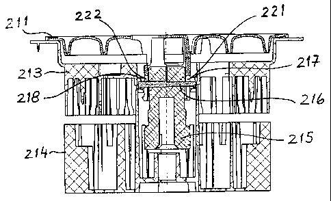
Fig. 20 shows a first cross-sectional view of reagent
container assembly 61 taken along a plane K-K in Fig. 12. In
this view the cover 211 rests on the top edge of the upper
part 213 of housing 212 of reagent container assembly 61.
As shown by Fig. 20, reagent container assembly 61 further
comprises the following additional parts which are arranged
CA 02560211 2006-09-20
- 23 -
within housing 212 and which are part of a locking
mechanism: a locking sleeve 215 and a locking pin 216.
Fig. 21 shows a partial perspective view showing the
position of locking pin 216 in the locked position of the
housing 212.
Figures 20 and 21 show the relative positions of the
different parts of the reagent container assembly 61 with
respect to each other when the reagent container assembly is
removed from its usual position in the analyzer.
Figure 20 shows the relative positions of the different
parts of the reagent container assembly with respect to each
other when the reagent containEsr assembly it rests e.g. on a
table in a parked state.
In the state of the reagent container assembly shown in Fig.
20, cover 211 rests on the upper part 213 of housing 212,
locking sleeve 215 is held by _Lts own weight in the position
shown in Fig. 20, and the end portions of locking pin 216
are in respective recesses 217 and 218 of upper part 213 of
housing 212. The latter recesses 217 and 218 are on the one
hand radial guides for the end portions of locking pin 216
and on the other hand they define the height at which
locking pin 216 is located. Fic~. 21 is an enlarged
perspective view showing the relative position of locking
pin 216 when the reagent container assembly is in the parked
state shown in Fig. 20.
In the state of the reagent container assembly shown in Fig.
20, cover 211 cannot be rotated around the vertical central
axis shown in Fig. 20, because two guide elements 221 and
CA 02560211 2006-09-20
- 24 -
222 of cover 211 connect it with locking pin 216 and this
connection keeps cover 211 in a fixed angular position.
In the state of the reagent container assembly shown in Fig.
20, locking sleeve 215 is connc=_cted by locking pin 216 with
upper part 213 of housing 212. In the state of the reagent
container assembly shown in Fig. 20, cover 211 is also
connected by locking pin 216 with upper part 213 of housing
212.
Fig. 21 shows how locking pin :?16 is locked in the recesses
217, 218 of upper part 213 of housing 212.
As can be appreciated from Fig. 20, the cross-sections of
the opposite end portions of locking pin 216 are different
and the sizes of recesses 217 and 218 are adapted thereto.
This arrangement defines only one possible position of
locking pin 216 with respect to upper part 213 of housing
212 when the end portions of locking pin 216 are lodged in
recesses 217 and 218 respectively. In the example shown by
Fig. 20, the end portion of loc king pin 216 on the right
side has a diameter d = 3 mm h8 and is lodged in recess 217
which has a diameter of 3 mm, whereas the end portion of
locking pin 216 on the left side has a diameter D = 4 mm h8
and is lodged in recess 218 wh_Lch has a diameter of 4 mm.
Fig. 22 shows a second cross-sectional view of reagent
container assembly 61 taken along a plane K-K in Fig. 12.
Fig 22 shows the relative positions of the different parts
of the reagent container assembly with respect to each other
when the reagent container assembly is carried by hand by a
user.
CA 02560211 2006-09-20
- 25 -
In the state of the reagent container assembly shown in Fig.
22, cover 211 is lifted off and thereby separated from the
upper part 213 of housing 212 by an air gap 225 of about 1,2
mm.
When a user lifts reagent container assembly 61 by gripping
cover 211 at suitable openings 243, 244 thereof, cover 211
is initially lifted off and thereby separated from the upper
part 213 of housing 212 until a hook 223 of cover 211
contacts upper part 213 of housing 212. When cover 211
reaches this position the whole assembly is lifted by the
user. The above described locking of the cover 211 and the
housing 212 remains however unchanged, because all above
mentioned parts remain locked and cannot be rotated with
respect to each other.
Fig. 23 shows a perspective view of conveyor 11 in Fig. 1.
As shown by Figures 14, 23 and 26, the lower part of a bolt
224 is mounted in an opening of the bottom wall 52 of bucket
51.
Figures 24 and 25 show two different side views of bolt 224.
As shown by Figures 24 and 25 'the lower part of bolt 224 has
projections 227 and 228 which are inserted in corresponding
recesses of the bottom wall 52 of bucket 51 and thereby
define the fixed angular position of bolt 224 with respect
to bucket 51.
As shown by Figures 24 and 25 the upper part of bolt 224 has
projections 231 and 232 which have different lengths,
projection 231 being longer than projection 232.
CA 02560211 2006-09-20
- 26 -
In the interior of lower part 214 of housing 212 there are
two recesses 233, 234 for receiving projections 231 and 232,
and recesses 233, 234 have depths corresponding to the
respective lengths of projections 231 and 232. This ensures
that housing 212 can only be connected to bolt 224 and
introduced into conveyor 11 at a single, defined angular
position of the reagent container assembly 61 with respect
to conveyor 11.
Fig. 26 shows a partial perspective view of the upper part
of bolt 224 in Fig. 23, when projections 231 and 232 of that
upper part pass through corresponding recesses of lower part
214 of housing 212. lower part 214 is free to rotate with
respect to bolt 224 which is fixedly mounted in the bottom
wall of bucket 51.
In order to install reagent container assembly 61 in the
analyzer shown in Fig. 1, assembly 61 is introduced in
chamber 54 of bucket 51 with an angular position at which
projections 231 and 232 of bolt 224 suitably enter the
corresponding recesses of lower housing part 214 and allow
bolt 224 to enter into a recess 226 (shown in Fig. 22) of
locking sleeve 215 and take the position shown by Fig. 27.
When reagent container assembly 61 reaches this position the
upper edge of upper part 213 of housing 212 comes to rest on
the upper edge of second ring ahaped body 14 of conveyor 11.
Fig. 28 shows a first perspective view of the cover 211 and
of locking sleeve 215 in Fig. 27. Fig. 28 shows that with
assembly 61 in the position shown in Fig. 27, locking pin
216 is inserted between guides 219 which are part of cover
211 and thereby keep cover 211 locked. Cover 211 is thus
kept in the position shown with respect to locking sleeve
215 also after insertion of reagent container assembly 61 in
CA 02560211 2006-09-20
- 27 -
cavity 54 of the conveyor, i.e. after installation of
assembly 61 in the analyzer.
Fig. 29 shows a second perspecaive view of the cover 211,
locking sleeve 215 and bolt 224 in Fig. 27. Fig. 28 shows
that with reagent container assembly 61 in the position
shown in Fig. 27, projections 231 and 232 are inserted in
respective recesses 235 and 236 of locking sleeve 215. This
prevents rotation of cover 211 with respect to housing 212
of reagent container assembly 61. Housing 212 (its upper and
lower parts 213, 214) are however allowed to slide downwards
and this movement brings locking pin out of its locked
position in upper housing part 213, and thereby housing 212
becomes free to be rotated by rotation of conveyor 11 on
which housing part 213 rests upon. Fig. 31 shows the
position of locking sleeve 215 and locking pin 216 when this
state is reached.
In the position shown in Fig. 31 reagent container assembly
61 rests on second rings shaped body 14 of conveyor 11. In
this position, projections 252, 253 in the upper edge of
body 14 engage corresponding recesses of housing 212 of
reagent container assembly 61 and thereby connect this
housing to conveyor 11. By stepwise rotation of conveyor 11,
housing 212 and thereby the array of reagent containers in
that housing can thus be rotated with respect to cover 211,
and this makes possible to access anyone of the reagent
containers for taking a reagent volume with the automatic
pipetting device 71. Cover 211 of reagent container assembly
61 remains stationary.
Although preferred embodiments of the invention have been
described using specific terms, such description is for
illustrative purposes only, and it is to be understood that
CA 02560211 2006-09-20
- LH -
changes and variations may be made without departing from
the spirit or scope of the following claims.