Language selection

Search

Patent 2560302 Summary

Third-party information liability

Some of the information on this Web page has been provided by external sources. The Government of Canada is not responsible for the accuracy, reliability or currency of the information supplied by external sources. Users wishing to rely upon this information should consult directly with the source of the information. Content provided by external sources is not subject to official languages, privacy and accessibility requirements.

Claims and Abstract availability

Any discrepancies in the text and image of the Claims and Abstract are due to differing posting times. Text of the Claims and Abstract are posted:

  • At the time the application is open to public inspection;
  • At the time of issue of the patent (grant).
(12) Patent Application: (11) CA 2560302
(54) English Title: POWER TOOL
(54) French Title: OUTIL A MOTEUR
Status: Deemed Abandoned and Beyond the Period of Reinstatement - Pending Response to Notice of Disregarded Communication
Bibliographic Data
Abstracts

English Abstract


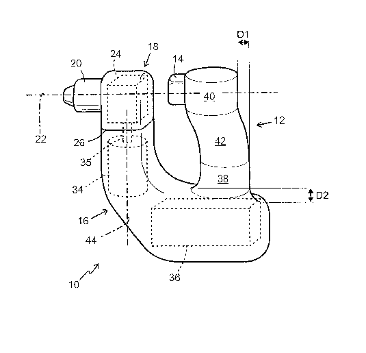
A power tool having a handle (12) and an active portion (18) for engagement
with a work piece. To optimize the engagement forces of the tool and to
provide an open top side allowing for alternative gripping, the handle (12)
and the active portion (18) are joined in a substantially U-shaped
configuration, where the handle and the active portion form free ends at
respective tops thereof, and that the active portion is located such that the
rotational axis lies on a level below said top.


French Abstract

L'invention concerne un outil à moteur comprenant un manche (12) et une partie active (18) destinée à venir en contact avec une pièce à usiner. Afin d'optimiser les forces de contact de l'outil et de mettre en place un côté supérieur ouvert offrant une fixation alternative, le manche (12) et la partie active (18) sont assemblés selon une forme sensible de U, le manche et la partie active formant des extrémités libres au niveau de leur sommet respectif et la partie active étant située de manière que l'axe rotatif se trouve sur un niveau inférieur audit sommet.

Claims

Note: Claims are shown in the official language in which they were submitted.


6
Claims
1. ~A power tool comprising a handle and an active portion for engagement with
a
work piece, characterized in that the handle (12) and the active portion
(18) are joined in a substantially U-shaped configuration, where the handle
and the
active portion form free ends at respective tops thereof, and that the active
portion is
located such that the rotational axis lies on a level below said top.
2. ~The power tool according to claim 1, wherein the rotational axis lies on a
level
between the top and at least the half of the handle (12).
3. ~The power tool according to claim 1 or 2, comprising a trigger provided at
a
front face and at the free end of the handle (12) to be controlled from above
or laterally
by at least one user finger.
4. ~The power tool according to any of the previous claims, wherein the active
portion (18) is arranged turnable around a shaft substantially perpendicular
to said
rotational axis.
5. ~The power tool according to claim 4, wherein said shaft is a drive shaft
for the
power tool.
6. ~The power tool according to any of the previous claims, comprising a
battery
pack (30) located below the handle (12) in a manner to localize the center of
gravity of
the power tool.
7. ~The power tool according to any of the previous claims, wherein the rear
face of
the power tool has a shape defined by two substantially vertical portions (32,
34)
located at the top and at the bottom of the handle, said vertical portions
(32, 34) being
joined by a curved portion (36) in such a manner that an upper portion (34) of
the
substantially vertical portions lies a distance (D1) closer than a lower
portion (32) of
the substantially vertical portions.

7
8. ~The power tool according to any of the previous claims, wherein the handle
is
connected to the power tool in such a manner that at front face of the handle
(12) is
ended at a level situated a distance (D2) higher than a rear face of the
handle.
9. ~A handle according to claims 7 or 8, wherein said distance (D1, D2) is
about 1-
3 cm.

Description

Note: Descriptions are shown in the official language in which they were submitted.


CA 02560302 2006-09-19
WO 2005/090008 PCT/SE2005/000342
Title: Power tool
Technical field
This invention relates to a power tool comprising a handle and an active
portion for
engagement with a work piece.
Background
I n power tools, i.e. hand tools having any kind of driving mechanism, for
example,
power drills, screw and nut drivers or grinders, the tool transfers work or
power to the
work piece. The rotational force imparts a torque to the tool. When the tool
is used, a
force is applied straight forward by the user's hand to push the rotating
active portion
against the work piece. For screwdrivers and drills, the necessary axial force
sometimes amounts up to 100 N.
There are many different types of power tools having handles of different
shapes and
locations. In order to demonstrate the importance of the position of the
handle in
relation to the axis of the rotating part, a short analysis of some of the
forces that may
appear in the tool is given below. Compared are forces between a conventional
power
drill and that of the present invention as shown in FIG. 1.
A conventional power drill/screwdriver has a handle positioned so that the top
portion
of the user's hand will be located a few centimeters below the rotational axis
of the
chuck. The following simple analysis will show that in order to apply a force
that is
directed exclusively along the axis of the chuck, one has to combine a forward
pushing
force with a downward turning force. This analysis does not account for the
rotational
force of the operating tool and not for the weight of the tool but is intended
to illustrate
one of the problems to be solved by the present invention.
Most easy is to analyze the forces acting in two points, namely the tool bit
tip and the
lower portion of the user's wrist. In the absence of any downward turning
force from the
wrist, the force f in the bit tip will be directed, as shown in FIG. 2, along
a line from the
wrist to the bit tip. According to FIG. 2, this force can be divided into two
components, a
straight forward directed horisontal force f(h) =f cos(a) and a straight
upward directed
vertical force f(v) =f sin(a). The upward directed force may cause a drilled
hole to be
oval or a driven screw to be deflected upwards. To eliminate the upward force,
a
downward torque M may be applied from the user's wrist. In the tool bit tip,
this torque
results in a force designated by f(m) and perpendicular to the pushing force.
When f(m)

CA 02560302 2006-09-19
WO 2005/090008 PCT/SE2005/000342
2
is sufficiently large to compensate for f(v), it will be
f(m) = f tan(a) = f x/y = M/r
as a function of the distances x, y, r and the torque M around the point rn.
The total
force f(t) directed exclusively forward is then
f(t) = f/cos(a)
whereby the pushing force f must be
f = f(t) cos(a)
and the torque M
M = f(m) r = f(t) x
Thus, the rotational force f(m) is the pushing force f multiplied by x/y. Tt~e
torque M is
f(t) multiplied by x and is independent from y. It may seem that such a large
value of y
should decrease the necessary torque M, while a large value of y only
decreases the
angle a so that, in practice, it will be less important to fully reduce f(m)
from f(v).
Typical values of x and y for a traditional screwdriver are x=11 and y=23,
whereby
r=25.5 cm and angle a=25.5 degrees. If a total force f(t) =100 N is desired,
then f=90 N,
f(m)=43 N and M=11 Nm. These values show that a large turning force is
required to
obtain a straight forward force: First a pushing force of 90 N has to be
applied, and this
pushing force must be combined with a downward force of 43 N having a torque
of 11
Nm to compensate for f(v). Supposing a lever arm of 5 cm at the user's wrist,
the
torque of 11 Nm gives rise to 2~0 N corresponding to the total force developed
in the
wrist. At these typical values, the conclusion is that only 45% of the total
force in the
wrist is used in the tool bit tip if the force is to be directed along the
tool rotational axis.
If x is decreased to 7 cm and the angle to 16.9 degrees, which are typical
values for the
present invention, the result is f=96 N, f(m)=29 N and M=7 Nm. In the same
manner
now 7 Nm using a lever arm of 5 cm corresponds to 140 N. Accordingly, 71 % of
the
applied force is utilized, and efficiency increases by 57% compared to tt-~e
previously
described conventional power tool.
As mentioned above, there are many different types of power hand tools. Some
have
their handles positioned so as to reduce the upward torque as shown above, for
example, certain types of hammer drills where the handle is positioned at the
rear end
with the upper part of the handle in line with the chuck axis. Some power
drills also
have a handle that allows for placing the hand near the axis f the chuck_

CA 02560302 2006-09-19
WO 2005/090008 PCT/SE2005/000342
3
Disclosure of the invention
According to an aspect of the invention, the handle and the active portion are
connected in a substantially U-shaped configuration, where the handle and the
active
portion form free ends at respective top portions thereof, and the active
portion is
located so that the rotational axis lies on a level below said top portions.
Accordingly, a novel feature of this invention is that the handle, in addition
of optimizing
the forces as described above, has an open top allowing alternative ways of
gripping
the handle.
Moreover, it is possible to easily make the active portion turnable to the
sides so that
the tool may be used in sideway directions for increased accessibility.
Other features and advantages with the invention will be apparent from the
followi ng
description and the claims.
Brief description of the drawing
FIG. 1 is a rear oblique view of a power tool according to the invention;
FIG. 2 is a graphical analysis of forces present when using the power tool;
FIGS. 3 and 4 show two different ways of holding a power tool according to the
invention; and
FIG. 5 is a lateral view of a turnable link between the active portion and the
power tool.
Detailed description
The power hand tool generally designated by 10 in FIG. 1 has a handle 12 and
an
active portion 18 connected in a substantially U-shaped configuration where
the handle
12 has an upward free end and the active portion 18 forms a second upward free
end.
"Active portion" 18 is to be understood as the part of the tool which
interacts with the
work piece material by, for example, a chuck 20 of a power drill. By such a
configuration according to FIG. 1, the distance from a user's wrist to the
rotationa I axis
20 of the power tool is reduced so as to transfer the applied force to the
work piece
material in a direction along the axis 20. In addition, there is a possibility
of an
alternative way of grasping the handle, FIG. 4, where the user's palm is
supporting the
upper portion of the rear face of the handle and the fingers are placed over
the to p of

CA 02560302 2006-09-19
WO 2005/090008 PCT/SE2005/000342
4
the handle. By using this grip it is possible to use the power tool on a high
level without
having to flex the wrist, which is a problem with the conventional type of
power tool,
where the wrist is flexed up to 45 degrees when working at high levels. The
lower part
16 of the tool section including the active portion 18 is adapted for being
capable of use
in a two-handed grip. As there is a large distance between the rotational axis
and the
second grip, the torque from the rotation of the motor 28 to the chuck 20 may
be
handled. Further, the upward torque described in the introduction of this
description,
can be entirely eliminated by the two-handed grip forming a lever where the
second
hand is holding back so that pushing force is applied from the first hand
only.
In order that the handle 12 should provide an optimal grip it is formed with
two vertical
portions 32, 34 joined by a curved portion 36. The vertical portions allow
application of
forward force, and at the same make time it possible to incline the hand by
being
laterally offset to each other by a distance D1 of about 1-3 cm. The handle 12
is
connected to the reminder of the power tool in such a manner that the front
face of the
handle is ended at a higher level than the rear face by a distance D2 of about
1-3 cm
which allows for a compact grip and a structure of a higher strength.
Power hand tools of this type are sometimes used in areas of low
accessibility. To
facilitate such use, the present invention makes it possible to make the
active portion
turnable sideways. The active portion 18, FIG. 1, shows the portion that can
be
arranged as a linkage 26 rotatable to the sides so that the power tool can be
used in a
lateral direction. FIG. 5 shows in detail how such linkage 26 can be
constructed. It is
comprised of two parts where one part may be clamped by a screw. It is
suitable to
have an arresting function at a 90 degree rotational position in both
directions, for
example by spring-loaded balls locking in grooves at 0 and 90 degrees. The
required
free space behind the chuck at a 90 degree rotation will then be small

CA 02560302 2006-09-19
WO 2005/090008 PCT/SE2005/000342
List of reference-numbered parts
10. Power tool
12. Handle
14. Trigger
16. Two-handed hand grip
18. Active portion
20. Ghuck or holder defining the rotational axis
24. Gearbox
26. Turnable coupling between power tool and active portion
28. Motor
30. Battery unit
D1. Distance between top and bottom portion of handle
D2. Distance between front and rear handle attachment

Representative Drawing
A single figure which represents the drawing illustrating the invention.
Administrative Status

2024-08-01:As part of the Next Generation Patents (NGP) transition, the Canadian Patents Database (CPD) now contains a more detailed Event History, which replicates the Event Log of our new back-office solution.

Please note that "Inactive:" events refers to events no longer in use in our new back-office solution.

For a clearer understanding of the status of the application/patent presented on this page, the site Disclaimer , as well as the definitions for Patent , Event History , Maintenance Fee  and Payment History  should be consulted.

Event History

Description Date
Time Limit for Reversal Expired 2009-03-09
Application Not Reinstated by Deadline 2009-03-09
Deemed Abandoned - Failure to Respond to Maintenance Fee Notice 2008-03-10
Letter Sent 2007-08-09
Request for Examination Received 2007-06-29
Request for Examination Requirements Determined Compliant 2007-06-29
All Requirements for Examination Determined Compliant 2007-06-29
Inactive: Cover page published 2006-11-20
Inactive: Cover page published 2006-11-16
Inactive: Notice - National entry - No RFE 2006-11-15
Inactive: Inventor deleted 2006-11-15
Application Received - PCT 2006-10-18
National Entry Requirements Determined Compliant 2006-09-19
Application Published (Open to Public Inspection) 2005-09-29
Small Entity Declaration Determined Compliant 2005-03-08

Abandonment History

Abandonment Date Reason Reinstatement Date
2008-03-10

Maintenance Fee

The last payment was received on 2007-02-09

Note : If the full payment has not been received on or before the date indicated, a further fee may be required which may be one of the following

  • the reinstatement fee;
  • the late payment fee; or
  • additional fee to reverse deemed expiry.

Patent fees are adjusted on the 1st of January every year. The amounts above are the current amounts if received by December 31 of the current year.
Please refer to the CIPO Patent Fees web page to see all current fee amounts.

Fee History

Fee Type Anniversary Year Due Date Paid Date
Basic national fee - small 2006-09-19
MF (application, 2nd anniv.) - small 02 2007-03-08 2007-02-09
Request for examination - small 2007-06-29
Owners on Record

Note: Records showing the ownership history in alphabetical order.

Current Owners on Record
CARL RIBBING
Past Owners on Record
None
Past Owners that do not appear in the "Owners on Record" listing will appear in other documentation within the application.
Documents

To view selected files, please enter reCAPTCHA code :


To view images, click a link in the Document Description column (Temporarily unavailable). To download the documents, select one or more checkboxes in the first column and then click the "Download Selected in PDF format (Zip Archive)" or the "Download Selected as Single PDF" button.

List of published and non-published patent-specific documents on the CPD .

If you have any difficulty accessing content, you can call the Client Service Centre at 1-866-997-1936 or send them an e-mail at CIPO Client Service Centre.

({010=All Documents, 020=As Filed, 030=As Open to Public Inspection, 040=At Issuance, 050=Examination, 060=Incoming Correspondence, 070=Miscellaneous, 080=Outgoing Correspondence, 090=Payment})


Document
Description 
Date
(yyyy-mm-dd) 
Number of pages   Size of Image (KB) 
Description 2006-09-18 5 210
Representative drawing 2006-09-18 1 11
Drawings 2006-09-18 4 43
Abstract 2006-09-18 1 51
Claims 2006-09-18 2 47
Reminder of maintenance fee due 2006-11-14 1 112
Notice of National Entry 2006-11-14 1 194
Acknowledgement of Request for Examination 2007-08-08 1 177
Courtesy - Abandonment Letter (Maintenance Fee) 2008-05-04 1 178
PCT 2006-09-18 2 88
Fees 2007-02-08 4 116
Correspondence 2007-09-23 2 60