Note: Descriptions are shown in the official language in which they were submitted.
CA 02561463 2011-01-17
DEVICE FOR MAINTAINING WING BALANCE ON A MULTI-SECTION HEADER
This invention relates to header of a crop cutting apparatus such as a
swather or a combine harvester which includes multiple sections defining a
center
section and two wing sections where the sections are balanced to maintain a
constant ground force across the width as the total ground force changes.
BACKGROUND OF THE INVENTION
Headers for a crop harvesting machine generally comprises a main
longitudinal support member in the form of an elongate tube which extends
across
substantially the full width of the header frame and defines a main structural
member
for the header frame. The tube carries a plurality of forwardly and downwardly
extending support beams which include a first portion extending downwardly and
a
second portion attached to a lower end of the first portion and extending
forwardly
therefrom toward a forward end of the support beams. The cutter bar is
attached to
the forward end of the support beams and is thus held thereby in a position
generally
parallel to the main support tube.
Many headers are of a type in which the cutter bar is intended to be in
a fixed rigid position relative to the main support tube so that the cutter
bar is not
intended to flex or float relative to the main structural tube in response to
changes in
ground contour.
This rigid type of header has the advantage that it allows more
accurate control of the position of the fingers or bats of the reel relative
to the cutter
bar so as to more accurately control the crop as it is swept onto the cutter
bar and
CA 02561463 2011-01-17
2
the table rearwardly of the cutter bar.
In this rigid header type, therefore, the support beams extending
forwardly from the main structural tube are substantially rigid and hold the
cutter bar
in fixed position.
Alternative types of header mount the cutter bar for floating or flexing
movement relative to the main structural support tube. This type of header is
used
to provide an improved action in following the contour of the ground and is
advantageous in some circumstances. Thus when cutting crops right at the
ground
it is desirable that the cutter bar of larger headers, greater than of the
order of 20
feet, is somewhat flexible to follow the ground contour. This type of header
however
has the disadvantage that the flexing or floating of the cutter bar relative
to the main
support tube causes movement of the cutter bar relative to the bats or fingers
of the
reel so that it is no longer possible to maintain a close tolerance between
the bats or
fingers and the cutter bar.
Various manufacturers provide a flexing cutter bar structure for
example the Soybean Header manufactured by Case IH under the Model No 820 or
1020.
Another type of header provides a cutter bar which is relatively rigid but
can float upwardly and downwardly relative to the main structural support tube
of the
header. This type of header again is used to allow close floating action of
the cutter
bar on the ground surface and one example is shown in the "Dial-a-matic Header
Height Control" available for various Deere and Company combine harvesters.
This
CA 02561463 2011-01-17
3
floating action of a cutter bar however occurs relative to the main structural
tube and
therefore relative to the reel so that the cutter bar to reel co-operation
cannot be
optimized.
It is known that rigid headers are conventionally flexibly mounted to the
propulsion machine, that is a swather tractor, combine harvester or pull type
frame,
and the header as one piece can generally follow the ground contour while the
cutting knife remains rigid.
It is also known that headers of this type can be controlled so that they
rotate around an axis at a center of the header in response to sensors which
detect
ground height so as to maintain the sides of the header as close to the ground
as
possible.
When cutting above the ground, a header of this type with a rigid knife
structure is most effective because the rigid knife structure allows maximum
cutting
speed and thus an improved cutting action.
When cutting on the ground with larger headers, it is known to have a
cutter bar which is mounted on the header so that it can flex or float across
its width
relative to the ground. Examples of such flexible cutter bars are shown in
U.S.
Patents 4,665,685 (Rupprecht) issued May 19, 1987 and 4,875,331 (Ostrup)
issued
October 24, 1989. Both of these arrangements show a cutter bar which is
mounted
on a skid and thus skids across the ground and flexes across its whole width
to
accommodate changes in height of the ground.
One disadvantage of the conventional flexible cutter bar is that it may
CA 02561463 2011-01-17
4
in some designs require a significantly reduced cutting speed since the
reciprocation
of the conventional sickle knife must be reduced in velocity to accommodate
the
curvature of the cutter blade which can occur when the whole of the cutter
blade is
flexible. Conventionally a flexible cutter bar of this type can flex as much
as a total
of five to six inches to accommodate the changes in ground height which occur
relative to the fixed part of the header frame which remains fixed and does
not
change relative to ground height.
A further disadvantage of a flexible cutter bar of this type is that it is
necessary to set the reel at a height which accommodates the upward movement
of
the cutter bar which can occur. The reel fingers therefore must necessarily be
spaced a significant distance from the cutter bar to avoid the possibility
that the
raised cutter bar interferes with the fingers and causes damage to either or
both.
This increased distance between the fingers of the reel and the cutter bar can
cause
irregular or improper feed of the crop material over the cutter bar
particularly in light
crop conditions so that an accumulation of cut crop on the cutter bar can
eventually
{
halt further cutting action leaving a part of the crop uncut and thus
unharvested.
The disadvantage of the rigid cutter bar design is that rather than
floating over a small area like a ridge or gopher mound, the rigid header
pushes dirt
in front of the sickle knife which impedes cutting and allows dirt to enter
the header
with the crop.
Up till now, therefore, the rigid header arrangement with its accurate
reel finger to cutter bar location is not fully satisfactory as it cannot
accurately follow
CA 02561463 2011-01-17
ground contour, and the flexible cutter bar design, which can follow ground
contour,
is also not fully satisfactory in view of the increased and varying space
between the
reel fingers and the cutter bar.
In U.S. Patent 4,956,966 (Patterson) issued September 1990 and
5 assigned to the present Assignee is disclosed a header which includes
drapers for
transporting the crop inwardly from the sides of the header toward the central
discharge section. The use of drapers can provide an arrangement which allows
the
header table to flex although the arrangement shown in the patent and the
product
manufactured in accordance with the patent provides a rigid header of the type
described above. The header of Patterson includes a central link by which the
position of the upper end of the header can be pulled toward or released from
the
supporting vehicle so as to change the angle of the frame of the header about
an
axis across the width of the header. A skid plate can be provided just behind
the
cutter bar which can run across the ground so that the change in angle of the
header
changes the angle of the cutter bar in front of the skid plate.
In U.S. Patent 5,464,371 (Honey) issued November 1995 to Honeybee
Manufacturing is disclosed a draper header of a type similar to that disclosed
in
Patterson.
In U.S. Patent 4,446,683 (Remple) issued May 1984 to Canadian Co-
operative Implements is disclosed a header for a swather which includes a
central
section and two wing sections in which the wing sections can pivot about a
forwardly
extending axis to allow the outer ends of the wing sections to be raised to a
height
CA 02561463 2011-01-17
6
as much as six feet from the ground. The cutter bar is continuous through the
pivot
axes so that the cutter bar flexes as the hinging action occurs. The patent
led to
development of a product manufactured by the above company which utilized the
arrangement of the wing sections and the flexible cutter bar. There were a
significant number sold but it is not being built any more and the arrangement
is no
longer commercial. The device supported the center section on the swather
tractor
but the wing sections were supported upon individual ground wheels mounted at
the
ends of the wing sections. It is necessary therefore to control the height of
the wing
sections by actuating movement of the ground wheels and this arrangement
therefore did not allow the system to accurately follow the ground contour.
In U.S. Patent 4,409,780 (Beogher) issued October 1983 to Kansas
State University is disclosed a header with three independent sections so that
two
wing sections can be folded rearwardly for transport. However this arrangement
does not provide a flexible arrangement which allows the cutter bar as a whole
to
accurately follow the ground contour.
In US Patent 6,675,568 (Patterson) issued January 13th. 2004 to the
present Assignees is disclosed a crop harvesting header for mounting on a
propulsion vehicle such as a swather tractor or combine harvester which
includes a
main frame structure supporting a crop receiving table with a cutter bar
across a
front of the table and side drapers on the table for moving the cut crop
toward a
discharge location of the header. The frame is divided into a central frame
portion
and two separate wing frame portions each arranged for pivotal movement
relative
CA 02561463 2011-01-17
7
to the central portion about a pivot axis extending in a plane parallel to the
forward
direction and intersecting the cutter bar so that, as the wing frame portions
pivot, the
cutter bar flexes in the area adjacent the respective pivot axis over a small
angle of
the order of 4 degrees to maintain the cutter bar following the ground. The
central
frame portion is mounted on two spring arms for upward and twisting floating
movement such that the total downward force on the ground, from that part of
the
weight of all of the portions of the header which is unsupported, can be
varied by
moving the support to change the total pressure of the header on the ground.
The
wing frame portions are connected to the central frame portion by
interconnecting
linkages which transfer weight from the wing frame portions to the springs of
the
central portion each including a respective balance beam arranged to balance
the
lifting force from the spring with the downward forces from the center portion
and
wing frame portion such that the downward force on a skid plate of each
portion on
the ground varies automatically as the total downward force is varied.
SUMMARY OF THE INVENTION
It is one object of the present invention to provide an improved header
based on the concept generally disclosed in the above Patterson patent.
According to a first aspect of the invention there is provided crop
harvesting header comprising:
a main frame structure extending across a width of the header for
movement in a forward direction generally at right angles to the width across
ground
including a crop to be harvested;
CA 02561463 2011-01-17
8
a mounting assembly for carrying the main frame structure on a
propulsion vehicle;
a crop receiving table carried on the main frame structure across the
width of the header;
a cutter bar across a front of the table arranged to move over the
ground in a cutting action and carrying a cutter knife operable for cutting
the crop as
the header is moved forwardly across the ground for depositing the crop onto
the
table;
a skid element extending across the width of the header for engaging
the ground so as to receive lifting forces from the ground at whatever points
of the
skid element contact the ground tending to lift the cutter bar;
a crop transport system on the table for moving the out crop toward a
discharge location of the header;
the main frame structure including a center frame portion, a first wing
frame portion and a second wing frame portion;
the first wing frame portion being connected to the center frame portion
by a first pivot coupling arranged for pivotal movement of the first wing
frame portion
relative to the center frame portion about a first pivot axis extending in a
plane
parallel to the forward direction;
the first pivot coupling thus acting to support weight from the first wing
frame portion at the pivot coupling while weight from the first wing frame
portion
outboard of the first pivot coupling tends to rotate the first wing frame
portion about
CA 02561463 2011-01-17
9
the first pivot coupling in a downward direction;
the second wing frame portion being connected to the center frame
portion by a second pivot coupling arranged for pivotal movement of the second
wing frame portion relative to the center frame portion about a second pivot
axis
extending in a plane parallel to the forward direction;
the second pivot coupling thus acting to support weight from the
second wing frame portion at the second pivot coupling while weight from the
second wing frame portion outboard of the second pivot coupling tends to
rotate the
second wing frame portion about the second pivot coupling in a downward
direction;
the mounting assembly including a first spring biased lifting member for
applying a first spring lifting force and a second spring biased lifting
member for
applying a second spring lifting force arranged at transversely spaced
positions on
the center frame portion of the main frame structure;
a first linkage for applying a first wing lifting force to the first wing
frame
portion in a direction to support the first wing frame portion against said
rotating
movement about the first pivot coupling;
a second linkage for applying a second wing lifting force to the second
wing frame portion in a direction to support the second wing frame portion
against
said rotating movement about the second pivot coupling;
a first balance system including a first balance beam pivotally
connected at a first pivot connection to the center frame portion of the main
frame
structure for applying a first center frame portion lifting force to the
center frame
CA 02561463 2011-01-17
portion;
the first balance beam being connected to the first linkage so as to
apply thereto the first wing lifting force;
the first balance beam being arranged to receive the first spring lifting
5 force from the first spring biased lifting member at a first lift position
therealong so as
to balance the first spring lifting force between the first center frame
portion lifting
force and the first wing lifting force;
and a second balance system including a second balance beam
pivotally connected at a second pivot connection to the center frame portion
of the
10 main frame structure for applying a second center frame portion lifting
force to the
center frame portion;
the second balance beam being connected to the second linkage so as
to apply thereto the second wing lifting force;
the second balance beam being arranged to receive the second spring
lifting force from the second spring biased lifting member at a second lift
position
therealong so as to balance the second spring lifting force between the second
center frame portion lifting force and the second wing lifting force;
wherein the mounting assembly is connected to the main frame
structure so as to allow adjustment movement of the main frame structure
relative to
the mounting assembly;
wherein there is provided a first element arranged to be responsive to
the adjustment movement and arranged in response to the adjustment movement to
}
1
CA 02561463 2011-01-17
11
operate on the first balance beam to change the balance of forces between the
first
wing lifting force and the first center frame portion lifting force in
proportion to the
amount of adjustment movement;
and wherein there is provided a second element responsive to the
adjustment movement to operate on the second balance beam to change the
balance of forces between the second wing lifting force and the second center
frame
portion lifting force in proportion to the amount of adjustment movement.
Preferably the first balance beam is arranged such that a distance of
the first pivot connection to the lift position is greater than the distance
of the first lift
position to the first compression member and wherein the second balance beam
is
arranged such that a distance of the second pivot connection to the second
lift
position is greater than the distance of the second lift position to the
second
compression member. In this way the forces in the compression member can be
maintained relative low allowing the use of flexible bushings as coupling
elements
and thus reducing friction.
Preferably the first and second balance beams are oriented such that
each has its longitudinal direction parallel to the forward direction. The
balance
beams can thus be located at the mounting of the lift arms at the forwardly
extending
frame members of the header. However another location and another orientation
can be selected for the beams.
Preferably the first balance beam is pivoted on the first pivot
connection at a forward end thereof and the second balance beam is pivoted on
the
CA 02561463 2011-01-17
12
second pivot connection at a forward end thereof. This allows the first and
second
pivot connections to be arranged as far forward as possible adjacent the
cutter bar.
Preferably the first balance beam and the first linkage is arranged such
that the first wing lifting force and the first center portion lifting force
vary
proportionally and wherein the second balance beam and the second linkage is
arranged such that the second wing lifting force and the second center portion
lifting
force vary proportionally.
Preferably the first spring biased lifting member includes a first lift arm
extending in the forward direction parallel to and underneath the first
balance beam
and wherein the second spring biased lifting member of the mounting assembly
includes a second lift arm extending in the forward direction parallel to and
underneath the second balance beam.
The above definition refers to the balance of forces being changed in
proportion to the amount of the adjustment movement. This is not intended to
be
limited to a direct or linear proportionality since the geometry involved may
require
different effects on the forces for different amounts of movement. However the
intention is that the adjustment movement through its length will cause some
change
in the balance of forces so as to maintain as far as possible the required
lifting force
on the wings to keep them properly positioned relative to the center portion.
In most cases, the mounting assembly will include at least one upper
mounting link connected to the main frame structure which is operable to
effect an
angle change of the crop receiving table and the cutter bar relative to the
ground
CA 02561463 2011-01-17
13
about an axis generally parallel to the cutter bar where the first and second
elements
are responsive to the change of angle.
In this case it is generally desirable that the first element is arranged to
reduce the first wing lifting force relative to the first center portion
lifting force when
the header is pivoted to increase the angle of the table relative to the
ground and
wherein the second element is arranged to reduce the second wing lifting force
relative to the second center portion lifting force when the header is pivoted
to
increase the angle of the table relative to the ground.
As an alternative or in addition, the mounting assembly can be
connected to the main frame structure in a manner which allows the height of
the
mounting assembly to be changed relative to the main frame structure to allow
the
skid element to rest on the ground in a floating action where the first and
second
elements are responsive to the change of height.
Preferably the first element is arranged to reduce the first wing lifting
force relative to the first center portion lifting force when the mounting
assembly is
lowered relative to the main frame structure and wherein the second element is
arranged to reduce the second wing lifting force relative to the second center
portion
lifting force when the mounting assembly is lowered relative to the main frame
structure.
In one arrangement, the first element is arranged to apply an additional
force to the first balance beam and the second element is arranged to apply an
additional force to the second balance beam. In this arrangement, the
additional
CA 02561463 2011-01-17
14
force can be applied by a first spring connected between the first balance
beam and
the mounting assembly and a second spring connected between the second balance
beam and the mounting assembly.
In another arrangement, the first element is arranged to move along
the first balance beam either the first lift position or a point of
application of one of
the first center portion lifting force and the first wing lifting force and
the second
element is arranged to move along the second balance beam either the second
lift
position or a point of application of one of the second center portion lifting
force and
the second wing lifting force.
In particular it is preferred in this construction that the first element is
arranged to move the first lift position along the first balance beam and the
second
element is arranged to move the second lift position along the second balance
beam.
In this arrangement, preferably the first spring biased lifting member
includes a first arm extending longitudinally of the first balance beam and
wherein
the first arm includes a first surface which is shaped such that its point of
contact
with the first balance beam moves longitudinally of the first balance beam as
an
angle between a longitudinal direction of the first arm and a longitudinal
direction of
the first balance beam changes and the second spring biased lifting member
includes a second arm extending longitudinally of the second balance beam and
the
second arm includes a second surface which is shaped such that its point of
contact
with the second balance beam moves longitudinally of the second balance beam
as
CA 02561463 2011-01-17
an angle between a longitudinal direction of the second arm and a longitudinal
direction of the second balance beam changes.
Preferably in this construction the surface of the first arm is curved
along its length and there is provided a first spring strip attached to the
first balance
5 beam and to the first arm with the curved surface of the first arm rolling
along the
first spring strip as the angle of the first arm relative to the first balance
beam
changes and the surface of the second arm is curved along its length and there
is
provided a second spring strip attached to the second balance beam and to the
second arm with the curved surface of the second arm rolling along the second
10 spring strip as the angle of the second arm relative to the second balance
beam
changes.
According to a second aspect of the invention there is provided a crop
harvesting header comprising:
a main frame structure extending across a width of the header for
15 movement in a forward direction generally at right angles to the width
across ground
including a crop to be harvested;
a mounting assembly for carrying the main frame structure on a
propulsion vehicle;
a crop receiving table carried on the main frame structure across the
width of the header;
a cutter bar across a front of the table arranged to move over the
ground in a cutting action and carrying a cutter knife operable for cutting
the crop as
CA 02561463 2011-01-17
16
the header is moved forwardly across the ground for depositing the crop onto
the
table;
a skid element extending across the width of the header for engaging
the ground so as to receive lifting forces from the ground at whatever points
of the
skid element contact the ground in a direction to lift the cutter bar;
a crop transport system on the table for moving the cut crop toward a
discharge location of the header;
the main frame structure including a center frame portion, a first wing
frame portion and a second wing frame portion;
the first wing frame portion being connected to the center frame portion
by a first pivot coupling arranged for pivotal movement of the first wing
frame portion
relative to the center frame portion about a first pivot axis extending in a
plane
parallel to the forward direction;
the first pivot coupling thus acting to support weight from the first wing
frame portion at the pivot coupling while weight from the first wing frame
portion
outboard of the first pivot coupling tends to rotate the first wing frame
portion about
the first pivot coupling in a downward direction;
the second wing frame portion being connected to the center frame
portion by a second pivot coupling arranged for pivotal movement of the second
wing frame portion relative to the center frame portion about a second pivot
axis
extending in a plane parallel to the forward direction;
the second pivot coupling thus acting to support weight from the
CA 02561463 2011-01-17
17
second wing frame portion at the second pivot coupling while weight from the
second wing frame portion outboard of the second pivot coupling tends to
rotate the
second wing frame portion about the second pivot coupling in a downward
direction;
the mounting assembly including a first spring biased lifting member
including a first lift spring for applying a first spring lifting force and a
second spring
biased lifting member including a second lift spring for applying a second
spring
lifting force arranged at transversely spaced positions on the center frame
portion of
the main frame structure;
a first linkage for applying a first wing lifting force to the first wing
frame
portion in a direction to support the first wing frame portion against said
rotating
movement about the first pivot coupling;
a second linkage for applying a second wing lifting force to the second
wing frame portion in a direction to support the second wing frame portion
against
said rotating movement about the second pivot coupling;
a first balance system including a first balance beam pivotally
connected at a first pivot connection to the center frame portion of the main
frame
structure for applying a first center frame portion lifting force to the
center frame
portion;
the first balance beam being connected to the first linkage so as to
apply thereto the first wing lifting force;
the first balance beam being arranged to receive the first spring lifting
force from the first spring biased lifting member at a first lift position
therealong so as
CA 02561463 2011-01-17
18
to balance the first spring lifting force between the first center frame
portion lifting
force and the first wing lifting force;
and a second balance system including a second balance beam
pivotally connected at a second pivot connection to the center frame portion
of the
main frame structure for applying a second center frame portion lifting force
to the
center frame portion;
the second balance beam being connected to the second linkage so as
to apply thereto the second wing lifting force;
the second balance beam being arranged to receive the second spring
lifting force from the second spring biased lifting member at a second lift
position
therealong so as to balance the second spring lifting force between the second
center frame portion lifting force and the second wing lifting force;
wherein the mounting assembly is connected to the main frame
structure so as to allow adjustment movement of the main frame structure
relative to
the mounting assembly;
wherein there is provided a first additional spring separate from and
additional to the first lift spring connected between the first balance beam
and the
mounting assembly, wherein the first additional lift spring is arranged to be
responsive to the adjustment movement and arranged in response to the
adjustment
movement to apply a first additional spring force to the first balance beam;
and wherein there is provided a second additional spring separate from
and additional to the second lift spring connected between the second balance
beam
CA 02561463 2011-01-17
19
and the mounting assembly, wherein the second additional lift spring is
arranged to
be responsive to the adjustment movement and arranged in response to the
adjustment movement to apply a second additional spring force to the second
balance beam.
According to a third aspect of the invention there is provided a crop
harvesting header comprising:
a main frame structure extending across a width of the header for
movement in a forward direction generally at right angles to the width across
ground
including a crop to be harvested;
a mounting assembly for carrying the main frame structure on a
propulsion vehicle;
a crop receiving table carried on the main frame structure across the
width of the header;
a cutter bar across a front of the table arranged to move over the
ground in a cutting action and carrying a cutter knife operable for cutting
the crop as
the header is moved forwardly across the ground for depositing the crop onto
the
table;
a skid element extending across the width of the header for engaging
the ground so as to receive lifting forces from the ground at whatever points
of the
skid element contact the ground in a direction to lift the cutter bar;
a crop transport system on the table for moving the cut crop toward a
discharge location of the header;
CA 02561463 2011-01-17
the main frame structure including a center frame portion, a first wing
frame portion and a second wing frame portion;
the first wing frame portion being connected to the center frame portion
by a first pivot coupling arranged for pivotal movement of the first wing
frame portion
5 relative to the center frame portion about a first pivot axis extending in a
plane
parallel to the forward direction;
the first pivot coupling thus acting to support weight from the first wing
frame portion at the pivot coupling while weight from the first wing frame
portion
outboard of the first pivot coupling tends to rotate the first wing frame
portion about
10 the first pivot coupling in a downward direction;
the second wing frame portion being connected to the center frame
portion by a second pivot coupling arranged for pivotal movement of the second
wing frame portion relative to the center frame portion about a second pivot
axis
extending in a plane parallel to the forward direction;
15 the second pivot coupling thus acting to support weight from the
second wing frame portion at the second pivot coupling while weight from the
second wing frame portion outboard of the second pivot coupling tends to
rotate the
second wing frame portion about the second pivot coupling in a downward
direction;
the mounting assembly including a first spring biased lifting member for
20 applying a first spring lifting force and a second spring biased lifting
member for
applying a second spring lifting force arranged at transversely spaced
positions on
the center frame portion of the main frame structure;
CA 02561463 2011-01-17
21
a first linkage for applying a first wing lifting force to the first wing
frame
portion in a direction to support the first wing frame portion against said
rotating
movement about the first pivot coupling;
a second linkage for applying a second wing lifting force to the second
wing frame portion in a direction to support the second wing frame portion
against
said rotating movement about the second pivot coupling;
a first balance system including a first balance beam pivotally
connected at a first pivot connection to the center frame portion of the main
frame
structure for applying a first center frame portion lifting force to the
center frame
portion;
the first balance beam being connected to the first linkage so as to
apply thereto the first wing lifting force;
the first balance beam being arranged to receive the first spring lifting
force from the first spring biased lifting member at a first lift position
therealong so as
to balance the first spring lifting force between the first center frame
portion lifting
force and the first wing lifting force;
and a second balance system including a second balance beam
pivotally connected at a second pivot connection to the center frame portion
of the
main frame structure for applying a second center frame portion lifting force
to the
center frame portion;
the second balance beam being connected to the second linkage so as
to apply thereto the second wing lifting force;
CA 02561463 2011-01-17
22
the second balance beam being arranged to receive the second spring
lifting force from the second spring biased lifting member at a second lift
position
therealong so as to balance the second spring lifting force between the second
center frame portion lifting force and the second wing lifting force;
wherein the mounting assembly is connected to the main frame
structure so as to allow adjustment movement of the main frame structure
relative to
the mounting assembly;
wherein the first balance beam is arranged such that the location of the
lift position thereon is movable to different positions longitudinally along
the first
balance beam and wherein the first balance beam is arranged such that to-said
adjustment movement causes movement of the location of the lift position along
the
first balance beam;
and wherein the second balance beam is arranged such that the
location of the lift position thereon is movable to different positions
longitudinally
along the second balance beam and wherein the second balance beam is arranged
such that said adjustment movement causes movement of the location of the lift
position along the second balance beam.
In many cases, as defined hereinafter there is provided a central
section mounted on the vehicle and two wing sections, which is in most cases
the
most practical arrangement providing sufficient flexibility without excessive
complication and expense. However the principles of this invention can be
applied
to alternative constructions which allow a plurality of sections to be carried
on a
CA 02561463 2011-01-17
23
propulsion vehicle and for the weight per unit length of each as applied to
the ground
to vary as the total weight is varied.
Thus in one example there may also be two additional outer wing
portions each pivotally mounted to an outer end of the inner wing potion and
each
having a respective pivot coupling and linkage which controls the position of
the
cutter bar as defined herein.
In most but not necessarily all cases, the header will include a
conventional reel. If included, the fact that the reel is mounted in
conventional
manner so that its position is in a specified location relative to the main
frame of
each portion ensures that it is in a specific relation to the cutter bar or
each portion.
In the preferred arrangement where the frame includes a center portion and two
wing portions, the reel may be located on two end arms each supported on the
outer
ends of the wing portions and also on a central arm mid way across the center
portion, since this provides three points where the inter-relation between the
reel and
the cutter bar is specified, even though the positions in between may vary. In
another arrangement, the reel may be mounted on four arms, two at each end and
two at the pivot points, which provides improved control over the reel to
cutter bar
distance but increases the complexity of the reel.
The reel is preferably of the type mounted on conventional arms
pivoted to the frame which allow adjustment of the height of the reel relative
to the
cutter bar. Suitable engineering arrangements for providing the necessary
flexing
and expansion of the sections of the reel to accommodate the flexing action of
the
CA 02561463 2011-01-17
24
header are well known to one skilled in the art. In addition, fixed reels
attached at
fixed location to end sheets of the header frame could also be used and the
invention is not limited in this regard.
The term "spring" as used in this document is not intended to be
limited to a particularly type of element which provides a spring or biasing
force but
merely defies any element which will allow resilient movement of one component
relative to another. This can be provided by a mechanical flexing link such as
a coil
or tension spring or can be provided by fluid such as air or hydraulic
cylinders and
the term is also intended to include the suitable mechanical couplings of
those links
to the required elements. Hydraulic cylinders with suitable accumulators for
taking
up and releasing fluid to the cylinders are effective in this regard.
This specification refers to "bending" of the cutter bar. This bending
movement can be obtained by providing a specific hinge between two parts of
the
bar or by providing a cutter bar which can flex sufficiently to accommodate
the
required bending without the necessity for an actual hinge defining a specific
pivot
axis.
The term "skid element" used in the above definition is not intended to
be limited to a particular component of the header and may be provided by any
element which physically engages the ground as the cutter bar and knife
elements
carried thereby proceed across the ground. Thus the skid element may be
provided
by the cutter bar itself or by an additional component behind the cutter bar.
In
addition, closely spaced rollers or other elements which roll over the ground
and
CA 02561463 2011-01-17
thus reduce friction may be used provided that the lifting force is spread
evenly
across the cutter bar to provide the floating action to which this invention
is directed,
although this is not generally necessary and not conventionally used.
The mounting assembly may be an adapter frame arranged for
5 connection of the header to an existing feeder house of a combine harvester.
However such an adapter is not essential and the mounting assembly may be
constituted by simply connecting elements which directly couple the header to
the
combine harvester.
Preferably, where each of the portions includes a conventional
10 horizontal main frame beam, the pivot coupling between the second frame
portion
and the first frame portion is arranged below the main beams.
Preferably the pivotal movement between the second frame portion
and the first frame portion is less than a total of 6 degrees and more
preferably less
than 4 degrees, which angles are sufficient to provide the flexibility of the
cutter bar
15 which is required without providing any additional movement for transport
or the like.
This limited movement provides a simple construction and may avoid the
necessity
for a hinge in the cutter bar while allowing a single high speed knife to move
along
the cutter bar through the hinge or flex section.
In most cases the header is unsupported by ground wheels such that
20 all lifting forces from the ground are communicated through said skid
element.
BRIEF DESCRIPTION OF THE DRAWINGS
Embodiments of the invention will now be described in conjunction with
CA 02561463 2011-01-17
26
the accompanying drawings in which:
Figure 1 is taken from US Patent 6,675,568 and shows the PRIOR
ART schematic rear elevational view of header of the general type with which
the
present invention is concerned with the combine harvester which acts as a
propulsion vehicle and the associated adapter being omitted for convenience of
illustration.
Figure 2 is taken from US Patent 6,675,568 and shows the PRIOR
ART schematic top plan view of the header of Figure 1.
Figure 3 is an isometric view from the rear and one side of one
embodiment of the header according to the present invention with the adapter
removed.
Figure 4 is a rear elevational view of the header of Figure 3.
Figure 5 is a cross sectional view along the lines 5-5 of Figure 4 of the
header of Figure 3 on an enlarged scale showing the trim coil spring.
Figure 6 is a cross sectional view similar to that of Figure 4 of second
embodiment of header.
Figure 7 is a cross sectional view of the embodiment of Figure 6
showing the header at an increased angle.
Figure 8 is a cross sectional view of the embodiment of Figure 6
showing the header at a float position relative to the mounting assembly.
Figure 9 is a cross sectional view of the embodiment of Figure 6
showing one portion at an increased scale at a first position.
CA 02561463 2012-04-18
27
Figure 10 is a cross sectional view of the portion of Figure 9 at a
second position.
In the drawings like characters of reference indicate corresponding
parts in the different figures.
DETAILED DESCRIPTION
Reference is made to US Patent 6,865,871 (Patterson) issued March
15th, 2005 which disclose details of an adapter for mounting a header on a
combine
harvester, the disclosure of which can be referred to for further details if
required.
Reference is also made to US Patent 6,675,568 (Patterson) issued
January 13th, 2004 which disclose details of a flexible header of the general
type with
which the present invention is concerned. Figures 1 and 2 and part of the
following
description are taken from that Patent for the convenience of the reader.
Further
details not included herein can be obtained by reference to that patent.
Figures 1 and 2 show in rear elevational view and in plan view
respectively a header 10 carried on an adapter 11 or mounting assembly
attached to
the feeder house 12 of a combine harvester. In Figure 1 the adapter is omitted
for
convenience of illustration.
The header 10 includes a frame 13 defined by a main rear beam 14
and a plurality of forwardly extending arms 15 which extend downwardly from
the
beam 14 and then forwardly underneath a table 16 which extends across the
header. At the forward end of the table 16 is provided a cutter bar 17. On top
of the
table 16 is provided a draper transport system 18 which carries the crop from
the
CA 02561463 2012-04-18
28
cutter bar across the header to a discharge location at the feeder house 12.
The
draper system 18 thus include two side drapers 18A extending from respective
ends
of the header inwardly toward the feeder house and a center adapter section
18B
which acts to feed the crop from the side drapers 18A rearwardly to the feeder
housing.
The header further includes a reel 19 including a beam on which is
mounted a plurality of reel bats (not shown) which are carried on the beam for
rotation with the beam around the axis of the beam. The beam is carried on
reel
support arms 19B which extend from the beam rearwardly and upwardly to a
support
bracket attached to the transverse main beam 14. The reel arms can be raised
and
lowered by hydraulic cylinders 19D connected between the respective arm and
the
beam 14.
In the embodiment shown the reel is mounted on three arms 19B
including two arms at the ends of the header and a single center arm. However
additional arms may be provided so that there are four such arms with two
center
arms being spaced apart either side of the adapter 11. It is well known to
provide an
arrangement of the beam and the bats which accommodate flexing movement of the
reel so that one end can be higher than the other end without damaging the
bats or
the reel structure. Various different arrangements for accommodating such
flexing
movement are known and can be incorporated into the arrangement described
herein, as is well known to one skilled in the art.
The above description of the header refers only schematically to the
CA 02561463 2012-04-18
29
construction since the details of the construction are well known to one
skilled in the
art.
Referring also to Figure 2, the adapter 11 comprises a frame 20 which
attaches to the feeder house 12 and carries at its lower end a pair of
forwardly
extending pivotal arms 21 which form respective first and second spring biased
lifting members and which extend forwardly underneath respective ones of the
frame
members 15 of the header. The pivotal arms 21 can pivot upwardly and
downwardly
about respective pivot pins 23 each independently of the other arm. Each arm
is
supported by a respective spring 24 attached to the respective arm 21. Thus
the
respective springs 24 provide respective first and second spring lifting
forces which
acts to pull up the respective arm 21 and provide a lifting force underneath
the
header at a lifting point partway along the respective frame member 15 and
underneath the draper 18 and the table 16.
At the center of the adapter is provided a link 26 which extends from
the frame 20 forwardly in the form of a hydraulic cylinder which allows
adjustment of
the length of the cylinder thus pivoting the header forwardly and rearwardly
about
the support point of the arms 21 on the underside of the header. Thus the
attitude of
the header, that is the angle of the table 16 to the horizontal can be tilted
by
operation of the cylinder forming the link 26.
In addition the attitude of the header about an axis extending forwardly
of the direction of movement that is at right angles to the transverse beam 14
is
effected by the independent pivotal movement of the arms 21 provided by the
CA 02561463 2012-04-18
springs 24 which act as a floatation system. In addition the whole header can
float
upwardly and downwardly on the springs 24 with the link 26 pivoting to
accommodate the upward and downward movement and the arms 21 pivoting about
the respective pin 23.
5 The table 16 provides behind the cutter bar 17 a skid plate 16A which
is arranged to engage the ground. Thus upward force is provided from the
ground
which tends to lift the header taking weight off the support springs 24. In
practice
the springs are adjusted so that the springs act to support the majority of
the weight
of the header leaving a relatively small proportion of the weight to rest on
the
10 ground. Thus the header can float upwardly and downwardly as the ground
provides areas of different height with one end of the header being movable
upwardly independently of the other end by independent flexing of the springs
24.
Thus the header tends to follow the ground level.
The above description applies both to the conventional rigid header
15 where the transverse beam 14 is substantially rigid along its length. In
the
embodiment of the type with which the present invention is concerned, the
header is
formed in a number of sections which are independently pivotal each relative
to the
next and in which adjustment of the lifting force provided by the springs 24
is
transferred to each of the sections proportionally so that each section can
float
20 upwardly and downwardly and each section applies a force to the ground
which is
proportional to the total force of the whole header.
Thus the beam 14 forms a main frame structure which is divided into a
CA 02561463 2012-04-18
31
number of separate pieces depending upon the number of sections of the header.
In the embodiment shown there are three sections including a center section or
center frame portion 10A, a first wing section or wing frame portion 1013 and
a
second wing section or wing frame portion 10C. The center section 1 OA is
mounted
at the adapter so that the arms 21 extend into engagement with the center
section.
The wing sections are pivotally connected to the center section such that each
can
pivot upwardly and downwardly about a respective pivot axis generally parallel
to the
direction of movement.
Thus the beam 14 is split into three portions each co-operating with a
respective one of the sections 10A, 10B and 10C and defining a main beam
therefor.
Each section of the beam 14 includes respective ones of the frame members 15
which support the respective portion of the table., Thus as best shown in
Figure 4,
there is a break 14A between the beam sections 14 of the center section 1 OA
and
one wing section 10B. The end most frame member 15A of the wing section 1 OB
is
arranged at the break. The end frame member 15B of the center section 10A is
spaced inwardly from the break leaving space for a pivot coupling 27 extending
from
the frame member 15A to the frame member 15B and defining a pivot pin 27A
defining a first pivot connection lying on the pivot axis between the wing
section 1 OB
and the center section 1 OA.
Thus the two sections 10A and 10B are supported each relative to the
other for pivotal movement of the wing section 10B about an axis extending
through
the pin 27A and through the break 14A so that the wing section is supported at
its
CA 02561463 2012-04-18
32
inner end on the center section but can pivot downwardly at its outer end so
that the
weight at the outboard end is unsupported by the center section and causes
downward or counter clockwise pivotal movement of the wing section 1 OB.
The wing section IOC is mounted in an identical or symmetrical
manner for pivotal movement about the other end of the center section 1OA. The
amount of pivotal movement allowed of the wing section relative to the center
section about the axis of the pivot pin 27A is maintained at a small angle
generally
less than 6 and preferably less than 4 as controlled by suitable mechanical
stop
members which are provided at a suitable location with the required mechanical
strength to support the wing frame section against upward or downward movement
beyond the stop members. Suitable stop members can be designed by a person
skilled in the art and the details of the stop members are not described
herein.
The outboard weight of the wing section 10B is supported on a linkage
30 which communicates that weight from the inner end of the beam 14 of the
section
10B through to the support for the center section 10A at the springs 24. The
linkage
is shown particularly in Figures 4 and 5 and includes a tension link 31
extending
from the inner end of the beam 14 to a bell crank 32 at the outer end of the
center
section 1OA on the beam 14 together with a further compression link 33 which
extends downwardly from the bell crank to a balance beam 34 located on the
center
section 1OA at its interconnection with the arm 21.
In general the linkage operates to transfer the outboard weight of the
wing section inwardly to the center section and at the same time to balance
the
CA 02561463 2012-04-18
33
lifting force provided by the springs 24 so that it is proportionally applied
to the
center section and to the wing section.
Thus in general the header is attached to the combine feeder house
using the float system described previously that supports the header so that
it can
be moved up when a vertical force about 1% to 15% of its weight is applied to
the
cutter bar from the ground. The reaction of the float linkage that typically
supports
85% to 99% of the header weight on the header is used to balance the weight of
the
wings.
The system is designed so that if the operator sets the float so that the
float system supports 99% of the header weight then the remaining 1 % will be
evenly distributed across the cutter bar. If the operator changes the float so
that
85% is supported by the combine harvester then the remaining 15% would also be
evenly distributed across the cutter bar without the operator making
adjustments.
Thus, not only is the total lifting force to each sections varied in
proportion to the
total lifting force but also that lifting force on each section is balanced
across the
width of section. As the sections are rigid between the ends, this requires
that the
lifting forces be balance between the ends to ensure the even distribution
across the
cutter bar of each section and thus of all the sections. This is achieved in
this
embodiment by a balancing system which includes a linkage connecting the force
to
the wing section and particularly the balancing beam 34. Thus the balance beam
34
as described in more detail hereinafter balances the lifting force applied to
the ends
of the center section relative to the lifting force which is applied to the
outboard
CA 02561463 2012-04-18
34
weight of the wing section so that the lifting force is even across the width
of the
header.
It will be appreciated that the inboard weight of the wing section is
transferred through the pivot 27 to the outboard end of the center section and
that
weight is transferred directly to the balance beam 34. Also the outboard
weight of
the wing section is transferred through the link 31 and the bell crank 32 to
the
balance beam 34. Yet further a lifting force from the arm 21 is applied to the
balance beam.
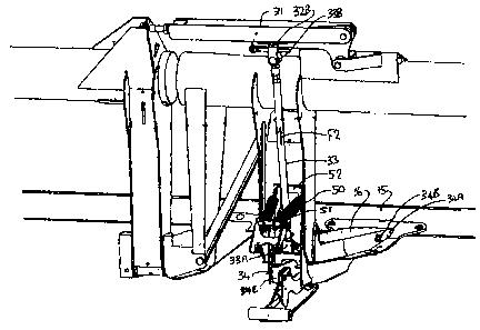
Thus reviewing Figures 3 and 4, the balance beam 34 is located above
the arm 21. The balance beam 34 has a forward end 34A which is pivotally
connected to the frame member 15 at a transverse pivot pin 34B. The arm 21
extends forwardly to a forward lifting point 21A which engages underneath a
forward
end 34A of the balance beam. Thus the lifting force from the arm 21 is applied
upwardly at the point 21A which is forward of the beam 14 and underneath the
table
16.
The balance beam 34 extends rearwardly from the forward end 34A
rearwardly to a rear end 34C to which is connected the compression link 33 at
a
bushing 33A. The compression link or compression member 33 thus applies an
upward pushing force which acts to support the outboard weight of the wing
section
and also applies some lifting force to the center section through the bell
crank 32.
The pivot pin 34B is attached to the center section so that some weight
from the center section, which is not carried on the bell crank, is
transferred to the
CA 02561463 2012-04-18
pivot pin and through that pin to the balance beam 34.
The lifting force from respective one of the first and second lift arms 21
is wholly applied at the respective one of the first and second lifting
positions 21A of
the balance beam. Thus these three forces are all applied to the balance beam
and
5 the balance beam acts to automatically proportion the forces relative to the
lifting
force.
Thus the support assembly includes a first component which is the pin
34B to provide a lifting force for the center frame portion. The support
assembly
which is the linkage includes a second component which is a tension link 33
10 arranged to provide a lifting force for the outboard weight of the second
or wing
frame portion.
The whole support assembly including the balance beam 34, the lift
arm 21 and the springs 24 are arranged to provide a floating movement for each
of
the first and second frame portions that is the center and wing frame portions
15 relative to each other and relative to the propulsion vehicle such that
upward
pressure from the ground on the skid element 16A which is greater in a
downward
force for a part of the weight of the header and supported by the lifting
force tends to
lift each of the center and wing frame portions relative to the propulsion
vehicle.
The balance beam 34 is arranged such that the first and second lifting
20 forces are varied proportionally as the total lifting force is varied. As
the force which
includes the force lifting the wing section and a part of the force lifting
the center
section, this can be balanced relative to the lifting force which applies a
lifting force
CA 02561463 2012-04-18
36
to the center section. The geometry of the balance beam and the linkage
including
the bell crank is arranged such that the balancing system defined thereby
provides
the lifting forces to the center section and wing section as defined above.
It will be noted that the linkage provided by the tension link 31,
compression link 33 and the bell crank 32 includes no spring connection and is
a
direct mechanical linkage so that the spring action or floating action of the
wing
section is provided by the spring 24.
The balance beam 34 extends parallel to the arm 21 so that the pivot
pins or bushings 34B and 33A have an axis at right angles to the balance beam
and
to the arm 21. The forces extend generally at right angles to the arm 21 since
the
arm 21 is generally horizontal underneath the header frame and underneath the
balance beam.
The bell crank 32 is located and supported on the beam 14 so that the
link 31 extends along the length of the beam 14 across the space 14A. Thus the
link
31 is located above the pivot 27A and communicates forces by tension.
The compression link 33 is pivotally attached to the bell crank at a
pivot connection pin 32B. The length of the arm 32C of the bell crank 32 can
be
adjusted by sliding the pin 32B along a slot 32D thus adjusting the mechanical
advantage of the bell crank to vary the mechanical advantage or moment of the
force transferred to the outboard weight of the wing section. Thus the bell
crank can
be adjusted so that the forces are balanced to produce approximately uniform
contact pressure between the ground and the skid shoe. The bell crank 32 is
CA 02561463 2012-04-18
37
pivoted at pin 32E carried on a support 32F attached to the frame. The link 31
attaches to the bell crank 32 at the pin 32G.
In the present arrangement as compared to the previous patent of
Patterson identified above, the arrangement for the balancing of the forces
from the
wing section and the center section relative to the lifting load are carried
out using a
compression link 33 as opposed to the tension link of the prior patent. This
compression link is attached to the balance beam 34 at a position closely
adjacent
its rear end. The forward end 34A of the balance beam is attached to the frame
member 15 at the pin 34B which is closely adjacent the cutter bar so that the
balance beam 34 provides a long lever length between the pivot pin 34B and the
compression link 33. The forward end of the lift arm 21 is located on the
balance
beam 34 at a position close to the rear end so that the distance between the
link 33
and its coupling 33A and the lifting point 21A is significantly smaller than
the
distance between the lifting point 21A and the pivot pin 34B which transfers
the load
from the main portion of the header. These lengths allow the forces in the
compression link 33 to be significantly smaller than the forces in the
corresponding
tension link in the above patent. In addition in the previous patent, the use
of a
tension link pulling down on the center section dramatically increases the
load
applied to the center section at the pivot point of the balance beam. The use
of the
geometry set forth herein and the use of a compression link in place of the
tension
link can reduce the forces applied at the pivot to as little as one sixth of
the previous
force. The reduction in the forces through the compression link allows the
couplings
CA 02561463 2012-04-18
38
33A at the lower end and 33B at the upper end of the link 33 to be formed as
rubber
bushings. These rubber bushings accommodate the necessary rotation which is
relatively small while providing low frictional forces while accommodating
that
rotation. These low frictional forces thus reduce the total friction through
the linkage
system to reduce inertia and to allow the pivoting action to occur more
effectively at
lower forces.
The balance beam 34 is located wholly within and protected by the
bottom portion of the frame member 15 which projects forwardly as a channel
underneath the table 16.
A further modification relative to the previous patent is provided by the
addition of a system to account for force changes on the balance beam due to
changes in angle of the header relative to the mounting assembly.
Thus in comparing Figures 6 and 7, it will be noted that one possible
movement of the header relative to the mounting frame 20 is obtained by
tilting the
header so as to increase the angle of the table 16 relative to the ground.
This
movement is obtained by extending the link 26 at the top of the header. That
link is
provided in the form of a cylinder which allows an end coupling 26A of that
cylinder
to move outwardly away from its support 26B on the frame 20. The header frame
then pivots about the forward end of the arms 21 at the connection between the
forward end 21A and the balance beam 34 so that the table tilts in the counter
clockwise direction as shown in figure 7 so that the cutter bar 16 moves
downwardly.
This moves the cutter bar downwardly relative to the skid plate so that the
cutting
CA 02561463 2012-04-18
39
action of the knife moves closer to the ground as the skid plate 16A runs over
the
ground.
This adjustment of the header is of course well known and it is
common that the operator initially sets the header in an aggressive position
so that
the angle of the table 16 upwardly and rearwardly from the cutter bar 17 is as
high
as possible to bring the knife as close as possible to the ground. In the
event that
this action causes the knife to dig into the ground or for excessive material
to be
lifted onto the table, the operator can then reduce the angle of the table by
turning
the table in the clockwise direction by shortening the link 26 so as to
slightly lift the
knife relative to the ground.
In a second adjustment movement of the header as shown by
comparing figures 6 and 8, the height of the feeder house 12 can be adjusted
so as
to raise and lower the frame 20 relative to the header. Thus the operator can
operate the drive system of the feeder house to lower the feeder house which
pushes the frame 20 downwardly so as to apply reduced lifting force to the
header
and therefore to allow greater weight to be applied from the header to the
ground.
Again the operator can initially set the machine with the feeder house
at a lowered position thus applying a heavier weight from the header to the
ground
and the operator can lift the feeder house if required so as to reduce the
pressure
from the header to the ground should this become necessary due to excessive
digging into the ground of the cutter bar or excessive lifting of material
from the
ground onto the table.
CA 02561463 2012-04-18
Careful analysis of the forces involved in the system and their relation
to the balance beam 34 have determined that, when the header angle is
increased
relative to the ground or the header is floated by pushing the feeder house
down
then the reaction pushing on the balanced channel from the wings goes up and
the
5 moment of that reaction also increases. At the same time the effect of
gravity is
decreased due to the change in angle of the pivot 27A and thus the forces
required
to balance the wings are reduced. As a result the effect of these movements is
such
that the effective weight of the wings is reduced so that pressure on the
ground from
the wings is reduced relative to the center section.
10 This careful analysis has therefore revealed that it is necessary to
compensate for these effects on the balance beam. Thus if the operator
operates
the link 26 so as to increase the angle of the header and/or if the operator
operates
the feeder house to move the frame 20 downwardly relative to the header then
action must be taken on the balance beam to reduce the upward force on the
15 compression link 33. The intention is that the pressure on the ground
remains
balanced regardless of this movement of the header relative to the frame 20.
In Figures 3, 4 and 5 is shown a first technique for applying a force to
the balance beam 34 when either of the above events occurs. This is obtained
by
providing one or more compensating springs 50 which are connected to the
balance
20 beam 34 and the frame 20. In the embodiment shown there are two such
parallel
springs each on a respective side of the compression link 33. The springs
extend
from a mounting pin 51 on the frame 20 and extend to a tower portion 52
standing
CA 02561463 2012-04-18
41
upwardly from the rear end of the balance beam 34. Thus the springs apply a
force
tending to pivot the balance beam 34 about the pivot point 21A at the forward
end of
the arms 21. This force therefore applies to the balance beam a tendency for
the
balance beam to rotate downwardly at the rear and thus reduces the forces
applied
from the balance beam upwardly onto the compression link 33. The amount of
reduction of this force is of course proportional to the force applied from
the springs
50. This force is dependent upon the amount of extension of the springs, that
is the
amount of movement between the frame 20 and the frame member 15 of the
header. In addition the amount of force is dependent upon the position of the
pin 51
relative to the forward end of the springs on the tower 52 of the balance beam
34.
This increase in distance between the tower portion 52 and the pin 51 can be
obtained either by the frame member 15 moving forwardly relative to the frame
20 or
by the frame member 15 moving upwardly relative to the frame member 20. It
will
be appreciated also that the changes of angle in the spring relative to the
tower
portion 52 to which they are attached will also provide some change in the
moment
applied by the springs about the pivot pin 21A of the balance beam. However
careful analysis of the matter and careful selection of the pivot points and
connection
points can allow the springs to provide the required level of compensation on
the
forces of the balance beam in dependence upon the movement of the frame
member 15 relative to the frame 20. Thus the compensating springs 50 define
first
and second elements arranged to be responsive to the adjustment movement and
arranged in response to the adjustment movement to operate on the first
balance
CA 02561463 2012-04-18
42
beam to change the balance of forces between the first wing lifting force and
the first
center frame portion lifting force in proportion to the amount of adjustment
movement.
In Figures 6 through 10 is shown an alternative arrangement for
affecting the forces on the balance beam 34. This arrangement avoids the
necessity
for an additional spring component 50 connected between the header and the
adaptor. This spring component can effectively provide the required forces but
provides in addition a further connection between those two components which
requires the connection to be completed or disconnected in the event that the
header is attached to or removed from the adaptor. This of course requires an
additional step to be undertaken by the operator which is inconvenient and if
forgotten can cause damage. The arrangement of Figures 6 through 10 thus
provides compensation for the forces on the balance beam 34 without an
additional
component. In general this arrangement provides the compensation by moving the
pivot point 21A relative to the balance beam 34.
In Figure 9 is shown an enlarged view the connection of the forward
end of the arm 21 to the balance beam 34. Figure 10 shows the same connection
point but in relation to the position of the components as shown in Figure 8.
It will be noted therefore that the pivot point indicated at 21C in Figure
9 is rearward from the pivot point indicated at 21D in figure 10. This
movement is
obtained by providing a curved surface 21 E on the part of the arm 21 which
engages
the underside 34E of a member 341 engaging the balance beam 34 at a fixed
CA 02561463 2012-04-18
43
position thereon. Thus in effect the pivot point rolls along the top surface
21 E as the
angle is changed between the arm 21 and the balance beam 34.
The member 341 comprises a resilient block 34F on the underside of
the balance beam 34 which can flex as the curved surface 21 E pivots across
that
surface of the block. A spring strap 34G is attached to a down-turned front
portion
34X of the block 34F connected thereto by a bolt 34J. The spring strap thus
includes a down-turned portion 34H at right angles to the surface 34E and the
spring
strap is bent at a right angle at a corner 34K. From the corner 34K, the
spring strap
extends across between the bottom surface 34E of the flexible block 34F and
across
the top surface of the curved end portion 21 E of the arm 21. The strap has a
rear
end 34L which is bolted to the surface 21 E by a bolt 34M. Thus the strap
provides a
connection between the block 34F and the curved surface 21 E. This strap
therefore
holds these elements at a fixed position along their length so that they
cannot move
longitudinally one relative to the other but as the angle changes between the
elements, the spring strap allows the pivot point to move along the bottom
surface
34E of the resilient block 34F as described above.
The block 34F has a top plate 34S and a front down-turned plate 34T
which form an abutment for engaging into a similarly shaped receptacle in the
balance beam 34. Thus the block 34F engages the balance beam and provides a
connection between the end of the arm 21 and the balance beam. The curved
surface 21 E can be formed by a pair of parallel plates bridged by the strap
34G.
One extreme position is shown in Figure 9 where the pivot point 24C is
CA 02561463 2012-04-18
44
close to the end of the block 34F remote from the leg 34H. The opposite
extreme
position is shown in figure 10 where the pivot point moves to a position
closely
adjacent the end of the strap adjacent the leg 34H. Intermediate positions can
of
course be assumed as the angle smoothly changes between these two extreme
positions. It will be appreciated that the pivot point is not a specific point
between
the two elements but occurs over a contact area due to the flexibility of the
strip 34G
and the block 34F under pressure from the curved surface 21 E.
It will be appreciated that movement of the pivot point of the balance
beam 34 from a position closer to the compression link 33 to a position
further away
from compression link 33 acts to reduce the actual compression force applied
to the
link 33. Thus the balance between the force applied to the center section of
the
header changes relative to the force applied to the wing section of the
header. In
this way the tendency of the wings to move upwardly because they become too
light
is compensated by this movement of the pivot point. Thus the shape and
arrangement of the balance beam and particularly its pivot point define first
and
second elements arranged to be responsive to the adjustment movement and
arranged in response to the adjustment movement to operate on the first
balance
beam to change the balance of forces between the first wing lifting force and
the first
center frame portion lifting force in proportion to the amount of adjustment
movement.
A person skilled in the art will be able to calculate the geometry
involved in providing the necessary movement of the pivot point in dependence
upon
CA 02561463 2012-04-18
the relative angles of the arm and the balance beam. This system therefore of
compensating the change in balance between the forces allows the compensation
to
occur without any additional elements which are connected between the header
and
the adaptor. The compensation occurs automatically so that the three sections
of
5 the header remain properly in balance during the changes of angle between
the
adaptor and the header which would otherwise cause the wings to become too
light.