Note: Descriptions are shown in the official language in which they were submitted.
CA 02561468 2006-09-28
FLOATING FOAM FOR FIRE FIGHTING
BACKGROUND OF THE INVENTION
Field of the Invention
[0001] Embodiments of the present invention generally relate to fire-fighting
and
more particularly to a foam for fighting fires in confined areas.
Description of the Related Art
[0002] Fires in confined areas can be extremely difficult to contain much less
to
extinguish due to a number of factors, for example, heat buildup, the
availability of fuel,
and the presence of toxic gases. These factors make delivery of fire
suppressant
material difficult. Hot combustion gases are confined and can be prone to
explosion
and can provide additional fuel to the fire. In addition, the combustion gases
normally
contain toxic levels of carbon monoxide gas, methane gas, and other toxic
substances.
[0003] Examples of confined areas susceptible to fires are storage tanks,
underground mines, and landfills. In coal mine fires, the abundance of fuel in
a
confined, poorly accessible area practically guarantees that the fire will
burn for
extremely long periods of time with resultant loss of production and great
property loss.
Many coal mines must be abandoned in the event of a fire because of the great
difficulty in extinguishing the fire. For example, the Jonesville coal mine
fire started
more than 30 years ago and is still burning. The town of Centrala, Pa. has
been
abandoned because seeping of noxious gases to the surface from a coal mine
fire that
began in 1961. The residents of the City of Youngstown have seen their
property
values drop to near zero due to the Percy mine fire in Fayette County, Pa.
that has
been burning for more than 30 years and they are concerned that they will lose
their
homes.
[0004] Fighting a fire in a mine in general comprises the steps of (i)
creating a seal
between the portion of the confined area involved in the fire and the
uninvolved portion
of the confined area; and (ii) introducing a fire suppressant or allowing the
fire to bum
itself out while maintaining the involved area sealed. Typically, the
atmosphere of the
1
CA 02561468 2009-08-26
involved area is drawn out after it has been sealed. In many cases, however,
removing
the atmosphere from the involved area is not possible or practical. In
addition, the
involved area is often flooded with water to attempt to extinguish the fire
and generally
reduce the temperature at the involved area.
[0005] Permanent and temporary seals or brattices are well known and have been
long
used in the mining field for sealing portions of a passage or shaft in a mine.
Brattices of
varying designs are used to for ventilation control and for emergencies, such
as in the
event of a fire. The brattice is fire proof and provides a suitable opening to
permit the
distribution of fire suppressant to the area involved in the fire.
[0006) In mine fires where the involved area is sealed, it is preferred that
the
atmosphere in the sealed area is drawn out so as to reduce as much as possible
the
oxygen in the sealed area to limit or slow the progress of the fire. This may
followed by
an attempt to flood the area with water. In the fires at Centralia, Percy, and
Jonesville
mines, described above, these procedures alone did not work with the resultant
loss to
the community and to the mine operators.
[0007] Water is not the most effective fire suppressant or extinguishing
material for use
in most confined area fires, particularly in fighting coal mine fires. In many
cases the
water does not reach the fire because of dips and fissures in the mine shaft
that in
effect pool, retain, or otherwise divert the water and prevent it from
reaching the fire. In
addition, the contact time of water that does reach the fire is short and the
water
evaporates and does not thoroughly penetrate and/or wet the fuel supporting
the fire.
[ooos] Conventional foam has been applied in attempting to extinguish coal
mine fires.
This foam is expanded with air that, of course, contains a substantial
concentration of
oxygen thus adding a highly combustible substance to the fire that becomes
available
to support combustion as the foam breaks down.
[0009] Other techniques include injecting carbon dioxide and/or nitrogen.
Nitrogen can
be used either in gaseous form or by being mixed with a surfactant and water
to
2
CA 02561468 2009-08-26
produce high expansion foam. The foam is used to suppress the fire as well as
forming
a barrier to direct gas flows around the mine. However, since the densities of
nitrogen
and carbon dioxide are substantially the same or greater than that of air, the
injected
gas/foam will not affect fires burning in the roofs of caverns unless the
entire involved
area is flooded with the gas or foam. Such an operation requires heavy
equipment and
a substantial amount of time. In one instance, a jet engine was used to
suppress such
a fire by injecting an entire mine with carbon dioxide.
[0010] Although not prone to the extremely long burning periods encountered in
coal
mine fires, other fire locations such as underground fuel storage tanks, above
ground
chemical storage tanks and the like present similar problems. It is difficult
to apply fire
suppressant material to the fire because of the danger to the firefighters
from explosion,
heat buildup and toxic gases.
[oo11] Therefore, there exists a need in the art for an improved fire
suppressant for
fighting fires in confined areas.
SUMMARY OF THE INVENTION
[0012] In one embodiment, a foam for extinguishing a fire is provided. The
foam
includes a surfactant; a non-flammable liquid; and an inert gas having a
density
substantially less than the density of air. In one aspect of the embodiment,
the density
of the foam is substantially less than the density of air. In another aspect
of the
embodiment, the non-flammable liquid is water. In another aspect of the
embodiment,
the inert gas is helium. In another aspect of the embodiment, the inert gas is
a mixture
of helium and nitrogen. In another aspect of the embodiment, a method for
using the
foam of the above embodiment is provided. The method includes the acts of
producing
the foam; and injecting the foam into a confined area to extinguish a fire in
the confined
area. In one sub-aspect, the confined area is a mine shaft. In another aspect
of the
embodiment, a method of producing the foam is provided. The method includes
the
acts of mixing the surfactant and the liquid to form a mixture; and injecting
3
CA 02561468 2006-09-28
the inert gas into the mixture to form the foam in a proportion so that the
density of the
foam is substantially less than the density of air.
[0013] In another embodiment, a method for extinguishing a fire in a confined
area is
provided. The method includes the acts of: providing at least one inlet to a
portion of the
confined area involved in the fire; proportioning a foam concentrate into a
non-
flammable liquid to form a foam concentrate/liquid mixture; forming a foam
fire
suppressant by injecting an inert gas, having a density substantially less
than the
density of air, under pressure to the foam concentrate/liquid mixture to
expand the foam
concentrate in the non-flammable liquid; and dispensing the expanded foam fire
suppressant through the inlet.
[0014] In one aspect of the embodiment, the inert gas is injected in a
proportion so
that the density of the expanded foam is substantially less than the density
of air. In
another aspect of the embodiment, the inert gas is helium. In another aspect
of the
embodiment, the inert gas is a mixture of helium and nitrogen. In another
aspect of the
embodiment, the method further includes the act of flooding the involved
portion with
water prior to introducing the foam.
[0015] In another aspect of the embodiment, the method further includes the
act of
forming a seal between the involved portion and uninvolved portions of the
confined
area. In one sub-aspect, the method further includes the act of drawing out at
least a
portion of the ambient atmosphere from the involved portion after it has been
sealed
thereby to reduce the amount of oxygen and gaseous fuel available to the fire.
[0016] In another aspect of the embodiment, the foam is expanded by a
dispenser
that proportions the gas into a concentrate/liquid stream thereby to initiate
expansion of
the foam. In one sub-aspect, the gas is proportioned to the concentrate/liquid
mixture in
a ratio of about 2 gallons per minute of the liquid/foam concentrate mixture
to about 1
cubic foot per minute of the gas. In another sub-aspect, the dispenser directs
the
expanded foam to the sealed portion involved in fire through the inlet.
4
CA 02561468 2006-09-28
[0017] In another aspect of the embodiment, the expanded foam is injected into
the
involved portion thereby to substantially close off contact between
combustible material
involved in the fire and the ambient atmosphere. In another aspect of the
embodiment,
the non-flammable liquid is water. In one sub-aspect, the concentration of the
foam
concentrate in water comprises between about 0.1 % to about 1.0%.
BRIEF DESCRIPTION OF THE DRAWINGS
[0018] So that the manner in which the above recited features of the present
invention
can be understood in detail, a more particular description of the invention,
briefly
summarized above, may be had by reference to embodiments, some of which are
illustrated in the appended drawings. It is to be noted, however, that the
appended
drawings illustrate only typical embodiments of this invention and are
therefore not to
be considered limiting of its scope, for the invention may admit to other
equally effective
embodiments.
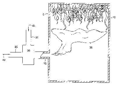
[0019] Figure 1 is a partial section view of a fire in a confined area being
extinguished,
according to one embodiment of the present invention.
DETAILED DESCRIPTION
[0020] Embodiments of the present invention are applicable to fires in various
confined areas, however, for purposes of description the invention will be
described in
connection with mine fires and more particularly with fires that occur in coal
mines. It
will be apparent, however, that the principles described in connection with
fighting a
mine fire are applicable to fires occurring at other confined areas.
[0021] Figure 1 is a partial section view of a fire 10 in a confined area 5
being
extinguished, according to one embodiment of the present invention. A high
expansion
foam concentrate is mixed with water. The water/foam concentrate mixture 40 is
expanded with a gas 45, such as helium, a mixture of helium and nitrogen, or a
mixture
of helium with any other inert gas, such that the overall density of the foam
35 is
substantially less than the density of air (hereinafter "light" foam).
Alternatively, any
CA 02561468 2006-09-28
inert gas having a density substantially less than that of air may be used to
lighten the
foam.
[0022] A proportioning device may be utilized for mixing the concentrate and
the
water. The gas 45 may be then injected into the foam concentrate/water mixture
40
under pressure for expanding the foam. A dispensing device may be employed to
inject
the expanded foam into the area involved in fire.
[0023] Commercially available high expansion foam concentrates may be used in
producing the fire suppressant foam. Class A foam concentrates are preferred
both for
their ability to isolate the fuel and because the proportioning of the
concentrate and
water is not as critical as for Class B foams. Such concentrates consist
primarily of a
surfactant dissolved in a non-flammable solvent and may further include
wetting agents
to aid in penetration of the fuel. Typically, the non-flammable solvent is
water. The
foam concentrate may be proportioned with water in percentages ranging from
about
0.1% by volume to about 1% by volume depending on the hardness of the water.
In
addition, the water may also be used as the primary propellant to distribute
the foam.
[0024] The choice of proportioning method is not critical. In some cases it
may be
desirable to premix the foam concentrate and water in a suitable container.
Such
proportioning method may be preferred in small fires where foam volume will be
relatively small. This method also lends itself for use in portable equipment.
Venturi
type or line proportioning devices are suitable for both portable systems and,
for
systems requiring a high volume of foam to be produced, are best suited in
situations
where water pressure is essentially constant in order to insure proper
proportioning of
water and concentrate and delivery of foam at a constant rate. Other types of
proportioners such as "around the pump" proportioners are well suited for
delivery of
large quantities of foam at a constant rate and as such are highly suited for
disbursement of high expansion foam in fighting mine fires.
[0025] The helium gas or helium/nitrogen mixture may be proportioned into the
water/foam concentrate mixture at a ratio of about 2 gal/min concentrate to 1
cubic foot
per minute (cfm) of helium or helium/nitrogen and several hundred cubic feet
of foam
6
CA 02561468 2009-08-26
can be produced from one gallon of the water/concentrate mixture. The flow
rate of the
water/concentrate mixture and thus the discharge rate of foam is dependent to
a large
extent on the available supply of helium or helium/nitrogen and water at the
site of the
fire.
[0026] The foam may be expanded and dispensed through a diffuser/dispenser
apparatus 30 that functions to introduce pressurized helium or helium/nitrogen
into the
water/foam concentrate stream to expand the foam and to dispense the expanded
foam.
[0027] The diffuser/dispenser apparatus 30 comprises an outer cylindrical
casing
through the interior of which extends a discharge line 15 parallel with the
axis of the
outer casing. The ends of the outer casing are closed around the discharge
line. One
end of the discharge line extends beyond the outer casing to define an intake
25 that
communicates with a source of the water/foam concentrate mixture. The opposite
end
of the discharge line extends beyond the outer casing at its opposite end to
define a
discharge 15 for dispensing the highly expanded foam. A helium or
helium/nitrogen
intake nipple 20 communicates through the outer casing for leading pressurized
helium
or helium/nitrogen into the outer casing. Alternatively, when, a mixture of
helium and
nitrogen is used, the diffuser/dispenser may have one nipple for helium and
one nipple
for nitrogen. A drain nipple (not shown) communicates with the interior of the
outer
casing for draining fluid from its interior. A portion of the discharge line
defines an
eductor (not shown) for entraining the helium or helium/nitrogen gas in the
water/foam
concentrate stream flowing through the discharge line. The eductor is formed
by four
openings in the wall of the discharge line. Each of the openings is spaced
ninety
degrees apart from the adjacent openings. A metal screen (not shown) is
disposed
about the discharge line to overlie the openings.
[0028] In operation, water and foam concentrate are mixed as the water flows
through a
conventional eductor. The water/foam concentrate stream flows into the intake
of the
7
CA 02561468 2006-09-28
intake of the diffuser while helium or helium/nitrogen is led into the
interior of the outer
casing through the nipple that communicates with the helium or helium/nitrogen
source.
The flow of the liquid stream past the eductor lowers the pressure in the
interior of the
outer casing that assists in drawing the helium or helium/nitrogen into the
flowing
stream. The introduction of the helium or helium/nitrogen initiates the full
expansion of
the foam as it leaves the discharge of the discharge line. The flow of the
liquid stream
acts to propel the foam from the diffuser. Liquid that passes out of the
discharge line
through the openings is drained from the interior of the outer casing through
the drain
nipple.
[0029] A diffuser nozzle (not shown) can be affixed to the end of the
discharge by
suitable means such as by the provision of external threads on the end of the
discharge
that threadibly engage corresponding internal threads in the diffuser nozzle.
The
diffuser nozzle can be of any conventional design and although the use of such
a
nozzle is not required it does serve to enhance the expansion of the foam
blanket.
[0030] The light foam 35 will allow a basic form of directional control of the
foam
because the light foam will float towards the ceiling of a cavern or mine
shaft. This
offers fire fighters several options in extinguishing an underground fire. In
the case of
the cavern roof fire discussed above, the light foam would have extinguished
the fire
without the need of a jet engine to flood the entire mine with carbon dioxide.
Instead,
the fire could have been easily extinguished by injecting only an amount of
foam
necessary to occupy the cavern roof volume. The light foam will also allow a
slug of
foam to be positioned in a mine shaft to displace any methane prior to a
carbon dioxide
sweep of the entire mine. Further, in many instances, the only available
injection point
to a burning mine shaft is to drill a relief well to the bottom of the shaft.
These
instances create analogous situations to the cavern roof fire, especially when
the fire is
not proximate to the bottom of the shaft, since the conventional foam/carbon
dioxide
would have to be injected until the level reached that of the fire.
8
CA 02561468 2006-09-28
[0031] While the foregoing is directed to embodiments of the present
invention,
other and further embodiments of the invention may be devised without
departing from
the basic scope thereof, and the scope thereof is determined by the claims
that follow.
9