Note: Descriptions are shown in the official language in which they were submitted.
CA 02561471 2006-09-28
-1-
ABSORBENT CLEANING PAD HAVING A DURABLE CLEANING SURFACE AND
METHOD OF MAKING SAME
FIELD OF THE INVENTION
The present invention relates to an absorbent cleaning pad and to a
method for fabricating the absorbent cleaning pad with a durable cleaning
surface.
BACKGROUND OF THE INVENTION
Modern floor cleaning implements employ disposable wipes or
cleaning sheets, which are releasably affixed to the head of a mopping
implement,
and which can conveniently be discarded and replaced after the cleaning sheet
is
sufficiently soiled. A side of the disposable absorbent cleaning sheet is in
contact
with a surface to be cleaned.
The cleaning sheet should be of sufficient integrity to withstand the
common mopping action stress and pressure and exhibit durability throughout
one
or more mopping sessions. In particular, the cleaning surface of the cleaning
sheet, which endures a significant portion of the stress and pressure should
be
adequately robust to substantially resist significant abrasion and
deformation.
Various disposable cleaning sheets have been proposed. For
example, a cleaning pad surface is disclosed in U.S. Patent No. 6,725,512,
which
CA 02561471 2006-09-28
_2_
illustrates a three-dimensional image imparted on the cleaning surface of a
cleaning pad. The three-dimensional image of the cleaning pad is intended to
induce the formation of lather due to pronounced surface projections that come
in
contact with the soiled surface and provide air passageways that are parallel
to the
plane of the substrate. The imaged nonwoven fabric is claimed to reduce the
potential of fiber contamination at the cleaning surface and is intended to be
used
in a vigorous manner without substantially abrading.
Nevertheless, there continues to be a need for improved cleaning
sheets or cleaning pads.
SUMMARY OF THE INVENTION
According to one aspect of the invention, a surface cleaning pad is
provided having a pad body comprising a matrix web formed from binder fibers
(or
a mixture of binder fibers and other fibers) and at least one cleaning surface
configured for contact with a surface to be cleaned. The density of the matrix
web
at the cleaning surface is greater than a density of the matrix web at a
location
spaced from the cleaning surface.
According to another aspect of the invention, a method is provided
for forming a cleaning pad body comprising a matrix web formed from binder
fibers and a cleaning surface. The method includes depositing a first
concentration
by weight of binder fibers so as to define the cleaning surface. A second
concentration by weight of binder fibers is deposited onto the first
concentration by
weight of binder fibers, wherein the second concentration by weight of binder
fibers is less than the first concentration by weight of binder fibers. The
first and
CA 02561471 2006-09-28
-3-
second concentrations by weight of binder fibers are bound together to form
the
matrix web.
According to yet another aspect of the invention, a method is
provided for forming a cleaning pad body comprising a matrix web formed from
binder fibers and a cleaning surface. The method includes depositing a first
portion
of substrate comprising binder fibers so as to define the cleaning surface. A
second portion of substrate comprising binder fibers is deposited onto the
first
portion of substrate. The first and second portions of substrate are bound
together
to form the matrix web structure. The matrix web is thereafter densified.
According to still another aspect of the invention, a surface cleaning
pad comprises a unitized airlaid composite body having a proximal zone
defining a
cleaning surface configured for contact with the surface to be cleaned and a
distal
zone adjacent the proximal zone on a side opposite the cleaning surface. The
proximal zone occupies a portion of the unitized airlaid composite body and
the
proximal zone comprises bonding fiber material. The distal zone occupies
another
portion of the thickness of the unitized airlaid composite body, and the
distal zone
comprises bonding fiber material, wherein the concentration by weight of the
bonding fiber material in the proximal zone is greater than a concentration by
weight of the bonding fiber material in the distal zone. The surface cleaning
pad
further comprises means for attaching the unitized airlaid composite body to a
cleaning implement.
CA 02561471 2006-09-28
-4-
BRIEF DESCRIPTION OF THE DRAWINGS
Exemplary embodiments of the invention will be described with
reference to the drawings, of which:
Figure 1 is a bottom view of an absorbent cleaning pad in accordance
with an exemplary embodiment of the present invention;
Figure 2 is a right side view of the absorbent cleaning pad illustrated
in Figure 1;
Figure 3 is an end view of the absorbent cleaning pad illustrated in
Figure 1;
Figure 4 is a top view of the absorbent cleaning pad illustrated in
Figure 1, including a cut-away portion of the cleaning pad;
Figure 5a is a cross-sectional partial end view of an embodiment of a
unitized airlaid composite suitable for use in the absorbent cleaning pad
illustrated
in Figure 1;
Figure 5b is a cross-sectional partial end view of another
embodiment of a unitized airlaid composite suitable for use in the absorbent
cleaning pad illustrated in Figure 1;
Figure 6 is a schematic, perspective view of an embodiment of a
system that can be used to form an absorbent cleaning pad according to an
aspect
of this invention;
CA 02561471 2006-09-28
-5-
Figure 7 is a schematic, sectional side view of the system illustrated
in Figure 6; and
Figure 8 is a flow chart illustrating exemplary steps of a process for
forming an absorbent cleaning pad according to another aspect of the
invention.
Figures 9 through 19 are schematic representations of exemplary
systems that can be used to form a unitized airlaid composite according to
aspects
of this invention.
DETAILED DESCRIPTION OF THE INVENTION
Although the invention is illustrated and described herein with
reference to specific embodiments, the invention is not intended to be limited
to
the details shown. Rather, various modifications may be made in the details
within
the scope and range of equivalents of the claims and without departing from
the
invention. Also, the embodiments selected for illustration in the figures are
not
shown to scale and are not limited to the proportions shown.
As used herein, the term "nonwoven web" defines a web having a
structure of individual fibers which are interlaid, but not in an ordered or
identifiable manner such as in a woven or knitted web. As defined by INDA, a
trade association representing the nonwoven fabrics industry, nonwoven fabrics
are generally sheet or web structures bonded together by entangling fiber or
filaments (and by perforating films) mechanically, thermally or chemically.
Nonwoven webs are formed from many processes, such as, for
example, air-laying processes, meltblowing processes, spunbonding processes,
CA 02561471 2006-09-28
-6-
coforming processes and bonded carded web processes. The term "airlaid
composite" implies that a non-woven web is formed by an air-laying process.
As used herein, the term "bi-component fiber" or "multi-component
fiber" refers to a fiber having multiple components such as fibers comprising
a core
composed of one material (such as a polymer) that is encased within a sheath
composed of a different material (such as another polymer or a thermoplastic
polymer). Some types of "bi-component" or "multi-component" fibers can be used
as binder fibers that can be bound to one another to form a unitized
structure. For
example, in a polymeric fiber, the polymer comprising the sheath often melts
at a
different, typically lower, temperature than the polymer comprising the core.
As a
result, such binder fibers provide thermal bonding due to melting of the
sheath
polymer, while retaining the desirable strength and fibrous structure
characteristics
of the core polymer. As an alternative to using a binder fiber, fibers are
optionally
spunbound or otherwise formed into a nonwoven structure.
As used herein, the term "concentration by weight" is defined as the
ratio of the weight of one component (e.9. binder fibers) within a structure
or a
portion of a structure to the weight of all components (e.g. binder fibers and
non
binder fibers) within the structure or the portion of the structure. In other
words,
the concentration by weight of a component is the weight ratio of that
component
to all components.
Referring to the overall structure of one exemplary embodiment,
Figures 1 thru 5a illustrate an absorbent cleaning pad designated generally by
the
numeral "110". Generally, the absorbent cleaning pad 110 has a pad body formed
from a unitized airlaid composite and having a cleaning surface configured for
cleaning contact with a surface to be cleaned and an opposite surface
configured to
CA 02561471 2006-09-28
_ 7 _
be positioned facing a cleaning implement. The surface cleaning pad also has a
backing (e.g., film or fabric) adhered to and substantially covering the
opposite
surface of the pad body and a pair of lofty cuffs adhered to the cleaning
surface of
the pad body.
As an alternative to applying a backing to a surface of the pad body
in the form of a separate component adhered to (or otherwise associated with)
the
pad body, a backing is optionally provided by chemically, mechanically, or
thermally modifying a surface of the pad body. For example, an agent is
optionally
applied to the pad body to provide a backing function. In such an embodiment,
an
agent (e.g., a fluoro-chemical compound or a sizing agent or an suitable
waterproofing agent) is optionally sprayed, coated, or otherwise applied to a
surface of the pad body. Alternatively, a layer of hydrophobic fibers or
nonwoven
can be used to provide a backing function.
An applied agent can provide a surface (or a portion of a surface) of
the pad body with selected characteristics. For example, the surface or
surface
portion can be rendered hydrophobic (to resist or prevent the passage of
fluid) or
hydrophilic (to encourage or promote the passage of fluid) through the surface
or
surface portion. In one use, the agent renders a surface of the pad body
hydrophobic to prevent liquid from passing from within the pad body through
the
surface. Such a surface is particularly advantageous for surfaces of a
cleaning pad
that face toward a cleaning implement to which it is attached.
More specifically, and according to one embodiment, the exemplary
absorbent cleaning pad 110 or cleaning sheet is provided with a unitized
airlaid
composite 120, supplementary dirt entrapment surfaces in the form of two lofty
cuffs 125, a backing layer 140, and two attachment members 145. Each lofty
cuff
CA 02561471 2006-09-28
_ 8 _
125 is folded into two equal segments and positioned along the length "B" of
the
unitized airlaid composite 120 although each cuff is alternatively formed from
a
single layer of material. Additional benefits and features of such cuffs are
disclosed
in U.S. Application No. 11/241,437. A portion of the width of each lofty cuff
125 is
bonded to a cleaning surface or side 152 of the unitized airlaid composite 120
using an adhesive 130. The backing layer 140 is adhered to the attachment
surface or side 155 of the unitized airlaid composite 120 using an adhesive
130
and folded around the width-wise sides 124 of the unitized airlaid composite
120,
thereby enclosing the width-wise sides 124. As discussed previously, the
backing
layer 140 is optionally eliminated, and the function of the backing layer 140
can
alternatively be eliminated or provided by applying an agent directly to a
surface or
a surface portion of the pad body or by otherwise chemically, mechanically, or
thermally modifying the surface of the pad body.
The unitized airlaid composite 120 of the exemplary embodiment
absorbs and retains fluids and/or other matter residing on a soiled surface
and
maintains the structural integrity of the cleaning pad 110 during use.
Although the
cleaning pad body of the exemplary embodiment is formed from a unitized
airlaid
composite 120, the cleaning pad body may be formed from many processes, such
as, for example, meltblowing processes, spunbonding processes, foaming
processes, coforming processes and bonded carded web processes. Accordingly,
the cleaning pad body is not limited to a unitized airlaid composite or air-
laying
process.
Nevertheless, it has been discovered that the optional use of a
unitized airlaid composite to form the cleaning pad body confers numerous,
significant advantages. These advantages are especially significant when the
cleaning pad body is formed from an airlaid composite suitable for direct
contact
CA 02561471 2006-09-28
-9-
with the surface to be cleaned according to aspects of this invention (e.g.,
without
the need for a layer of material interposed between a surface of the airlaid
composite and the surface to be cleaned).
For example, it has been discovered that by using a unitized airlaid
structure for the pad body, in such a way as to eliminate the need for a layer
interposed between the airlaid composite and the surface to be cleaned (i.e.,
wherein a surface of the airlaid composite is exposed in the final product),
the
expense and complexity associated with converting processes can be reduced.
More specifically, it has been recognized that cost and complexity are
introduced
when layers of different materials need to be assembled during the process of
converting raw materials into a finished product. Such assembly requires
machinery that is configured to synchronize the positioning of webs of
components
as they travel continuously along a machine direction. Also, it has been
recognized
that processes for converting such raw materials into a final product are
l~ complicated by the fact that raw materials have different strength and
stretch
characteristics. Accordingly, reducing the number of raw materials that need
to
come together to form a finished product in the converting process (or perhaps
even eliminating the need to assemble any components) sharply reduces the cost
and complexity associated with converting processes.
Additionally, it has been discovered that the utilization of a unitized
airlaid construction, without supplemental surface-contacting layers
preventing
contact between the airlaid composite and a surface to be cleaned, also
reduces
raw material costs. Because raw materials are often supplied by different
companies and may need to be cut to particular specifications, there is often
a
waste of material associated with the procurement of such materials for use in
converting processes. Also, when such materials are purchased from various
CA 02561471 2006-09-28
-10-
suppliers or vendors, the overhead (and margin) associated with such suppliers
and vendors are added to the cost of the final product.
Additionally, it has been discovered that the use of laminations
bonded together to form a cleaning pad structure introduces extra cost
associated
with such lamination materials. More specifically, such laminations may
require
additional raw materials. Accordingly, the elimination of supplemental layers
such
as laminations has been discovered to reduce the cost associated with the
cleaning
pad product.
The lofty cuffs 125 serve to facilitate the removal of larger soils from
the surface being cleaned by contacting and trapping the soil particles. The
lofty
cuffs 125 typically trap soil particles (e.g., dog hair and similar objects)
that are
too large for the airlaid composite 120 to trap.
The backing layer 140 substantially prevents fluid from passing from
the unitized airlaid composite 120 to a cleaning implement to which it is
attached,
to maintain an unsoiled cleaning implement. The backing layer 140 also
substantially limits airlaid composite absorbent particles from escaping out
of the
exposed width-wise sides 124 of the unitized airlaid composite 120.
The attachment members 145 provide an attachment mechanism to
temporarily couple the absorbent cleaning pad 110 to a floor cleaning
implement,
for example. Additional benefits and features of attachment mechanisms are
disclosed in U.S. Application Nos. 11/241,138 and 11/240,949. The disclosure
of
U.S. Application Nos. 11/241,138 and 11/240,949 are incorporated herein by
reference in their entirety.
CA 02561471 2006-09-28
-11-
Referring still to Figures 1 thru 5a, the cleaning sheet of the
exemplary embodiment is formed from a unitized airlaid nonwoven composite. The
airlaid nonwoven is a highly absorbent, lofty fabric or composite that is
relatively
cost competitive with similar weight nonwovens. The airlaid composite is
composed of at least binder fibers and absorbent components such as cellulosic
fibers and/or superabsorbent particles which are suspended in a web-like
arrangement. Other additional materials (e.g., emulsion polymer bonding
systems, hotmelt, powder) are optionally present, and components of the
airlaid
may be needled or hydroentangled. The exemplary airlaid composite 120 is a
singular unitized body providing a cleaning surface or side 152 that is in
direct
contact with the soiled surface and an opposing attachment surface or side 155
of
the absorbent cleaning pad 110 in contact with the cleaning implement (not
shown). By way of non-limiting example, and for purposes of illustration only,
the
unitized airlaid composite 120 of the exemplary embodiment is optionally
provided
with a squeeze-out value of approximately 50% and an absorbent capacity of at
least approximately 28 grams/gram, although higher or lower values for squeeze-
out and absorbent capacity are contemplated as well. The squeeze-out value is
the
cleaning pad's capacity to retain absorbed fluid, even during the pressures
exerted
during the cleaning process. However, a certain amount of fluid is
advantageously
released during use in order to efficiently clean a surface such as a floor. A
test
method for determining squeeze-out value is provide in U.S. Patent No.
6,601,261,
to Holt et al.
The unitized airlaid composite 120 is optionally capable of retaining
350 grams of de-ionized water. As will be described in further detail below,
the
use of a unitized airlaid composite structure to form the pad body of a
cleaning pad
advantageously allows for better control of squeeze-out value. In other words,
the
CA 02561471 2006-09-28
-12-
structure and composition of the unitized airlaid can be modified in such a
way as
to increase or decrease squeeze-out value and to render squeeze-out value more
predictable. This is particularly advantageous when, according to aspects of
this
invention, the cleaning pad does not include a layer of material between the
pad
body and the surface to be cleaned (i.e., where an exposed surface of the pad
body is configured for direct contact with a surface to be cleaned).
The unitized airlaid composite 120 of the exemplary embodiment is
substantially rectangular in shape having a length B and width A. However, the
shape of the unitized airlaid composite 120 is not limited to a rectangular
shape, as
the unitized airlaid composite may comprise any shape or form.
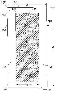
Referring to Figure 5a specifically, a cross-sectional detailed view of
the unitized airlaid composite 120 of the exemplary embodiment is illustrated.
The
unitized airlaid composite 120 includes two or more zones, i.e. a proximal
zone 121
(located proximal to and defining the cleaning side 152) and a distal zone 122
(located distal from the cleaning side 152 but adjacent to proximal zone 121
on a
side opposite the cleaning side 152). The proximal zone 121 comprises binder
fibers (e.g. bi-component fibers) and the distal zone 122 comprises both
binder
fibers and non-binder fibers such as absorbent components (e.g. cellulosic
fibers
and/or super absorbent particles). The concentration by weight and/or the
density
of binder fiber material in the proximal zone 121 is preferably, but not
always,
greater than the concentration by weight and/or the density of binder fiber
material in the distal zone 122.
The proximal zone 121 is contiguous with (and defines) the cleaning
side 152 of the unitized airlaid composite 120 that is in contact with the
soiled
surface in use. Accordingly, the proximal zone 121 is composed of a material
CA 02561471 2006-09-28
-13-
sufficiently durable such that the proximal zone 121 retains its integrity
during
cleaning and abrading actions against the soiled surface. This characteristic
of the
unitized airlaid composite 120 is particularly advantageous when, according to
aspects of this invention, an exposed surface of the pad body is positioned
for
direct contact with a surface to be cleaned. Additionally, when the proximal
zone
121 is provided with the integrity needed to withstand direct contact with the
surface to be cleaned, the cleaning pad can be provided with improved
integrity or
can be provided with comparable integrity (as compared to conventional
products)
with less material (e.g., by means of the elimination of any layer interposed
between the pad body and the surface to be cleaned, by the utilization of less
material, etc.).
The proximal zone 121 interacts with the soil as it passes over the
soiled surface, loosening and emulsifying tough soils and permitting them to
pass
freely into the distal zone 122 of the pad. The proximal zone 121 can
facilitate
other functions, such as polishing, dusting, scraping, and buffing a surface.
In
addition to interacting with the soiled surface, the proximal zone 121 also
serves as
a fluid acquisition zone that delivers fluid to the distal zone 122 of the
unitized
airlaid composite 120.
The distal zone 122 is contiguous with and defines the attachment
side 155 of the unitized airlaid composite 120 that is in contact with the
cleaning
implement (not shown). The distal zone 122 facilitates the storage of clean
and/or
soiled liquid as well as cleaning solution removed from the surface being
cleaned.
The distal zone 122 also filters and traps the dirt particles in the soiled
liquid. In
addition to storing and filtering liquid, the distal zone 122 facilitates the
release of
the stored liquid. Accordingly, the dirt particles are retained within the
distal zone
122 after the liquid is released from the distal zone 122. Additionally, as
discussed
CA 02561471 2006-09-28
-14-
previously, the squeeze-out value of the cleaning pad is optionally controlled
to
retain a sufficient amount of liquid.
The proximal zone 121 may represent approximately five to
approximately fifty percent or more of the entire thickness of the unitized
airlaid
composite 120. In composite 120, the proximal zone 121 extends from the
exterior cleaning surface or side 152 to a depth spaced from side 152. The
distal
zone 122 extends from the proximal zone 121 to the attachment surface or side
155 of the composite 120. The zones 121 and 122 are integral with one another
by virtue of the process used to form the composite 120, described in greater
detail hereafter.
The unitized airlaid composite 120 is composed of at least binder
fibers and absorbent matter such as fluff pulp and a super absorbent polymer
(SAP). The relationship between the concentration by weight of binder fibers
and
the concentration by weight of absorbent matter has an impact upon the tensile
strength and the absorbency of the unitized airlaid composite 120. As used
herein,
the term "tensile strength" is defined as the amount of force a fiber or
material
web can withstand before breaking or permanently deforming. Prior to breaking
or
permanently deforming, the fiber or material web may elastically deform.
The web tensile strength is substantially linearly proportional to the
concentration by weight of binder fibers in the unitized airlaid structure.
Hence, as
the percentage by weight of binder fibers increases relative to the percentage
by
weight of absorbent matter in a particular portion of the composite, the
tensile
strength of the unitized airlaid composite increases in that portion. However,
it
should be noted that as the percentage by weight of binder fibers increases in
a
particular portion, the concentration by weight of absorbent matter decreases,
CA 02561471 2006-09-28
-15-
thereby reducing the absorbency of the unitized airlaid composite 120 in that
portion. The graph below illustrates the relationship between the unitized
airlaid
web tensile strength and the percentage of binder fibers within the unitized
airlaid
structure.
Airlaid Web Tensile Strength Vs. Binder Fiber Percentage
6
4 .
Teneile Strength (lb.)
3 . .._.. .. . .... . . ... . . . _ .._..
1 . .. ._
0.-.. .__._.... __._. _. . _.. . ..... .. . ___..... . ... _ ....
0 5 10 15 20 25 30 35 40
Binder Fiber Percentage ( % /
Airlaid Web Tensile Strength Vs. Binder Fiber Percentage
In addition to tensile strength, it has been discovered that an
advantageous characteristic of an airlaid composite used in a pad body of a
cleaning pad according to aspects of the invention is that the airlaid
composite will
have sufficient tear strength to withstand the forces encountered during the
cleaning process, which may include scraping and other vigorous actions under
pressure. For example, for embodiments in which the cleaning surface of the
cleaning pad is an exposed surface of airlaid composite, the airlaid composite
should be able to withstand forces encountered with rough or irregular
cleaning
surfaces without tearing. It is recognized that surfaces to be cleaned (e.g.,
floors,
walls, and other similar surfaces) may include surface features capable of
engaging
CA 02561471 2006-09-28
-16-
selected portions of the cleaning pad. If, for example, the head of a nail or
screw
or staple protrudes from a surface to be cleaned, that surface feature may
engage
the cleaning pad while a force of continued movement is applied to the
cleaning
pad, thereby encouraging a tear in the pad and/or possible tinting from zones
of
the pad exposed by such a tear.
It has further been discovered that, while maintaining a sufficient
tensile strength and a sufficient tear resistance as described in further
detail below,
it is also advantageous to maintain a reduced coefficient of friction between
the
exposed surfaces of the cleaning pad and the surface to be cleaned. In other
words, the friction encountered when the cleaning pad is moved in sliding
relationship with a surface to be cleaned is advantageously maintained at an
acceptable level in order to facilitate comfortable use of the cleaning pad.
If the
coefficient of friction between the cleaning pad and the surface to be cleaned
becomes too great, the effort needed to slide the cleaning pad with respect to
the
surfiace to be cleaned may become unacceptable to users of the cleaning pad.
The
problems associated with an excessive coefficient of friction are exacerbated
when
a user of such a pad presses hard to remove stubborn dirt deposits. Details
with
respect to this coefficient of friction will be described later in greater
detail.
The foregoing characteristics of tensile strength, tear resistance, and
coefficient of friction have been discovered to compete with one another. It
is
believed that articles, such as airlaid composites, having increased tensile
strength
and tear resistance often have an increased coefficient of friction, while
materials
having a reduced coefficient of friction may have compromised tensile strength
and
tear resistance properties. Accordingly, it has been discovered that a
cleaning pad
having a cleaning surface at least partially defined by an exposed region of a
CA 02561471 2006-09-28
-17-
unitized airlaid composite preferably balances the characteristics of tensile
strength, tear resistance, and coefficient of friction.
According to the exemplary embodiment, to achieve a greater
concentration by weight of binder fibers in the proximal zone 121, the air-
laying
apparatus is configured to distribute a greater concentration by weight of
binder
fibers at the proximal zone 121, as compared to the distal zone 122. In
another
embodiment, the binder fibers of the proximal zone 121 may be compacted or
densified to increase the density of the proximal zone 121. In yet another
embodiment, the individual binder fibers of the proximal zone 121 may have a
higher basis weight than the binder fibers of the distal zone 122, as binder
fibers of
higher basis weight typically exhibit greater tensile strength. These
exemplary
embodiments will be described in further detail with reference to the airlaid
fabrication process.
In the exemplary embodiment illustrated in Figure 5a, the web of
binder fibers in the proximal zone 121 is of greater concentration by weight
than
the web of binder fibers in the distal zone 122. It has been discovered that a
proximal zone 121 comprising at least a fifty percent greater concentration by
weight of binder fibers than the distal zone 122 improves the durability of
the
unitized airlaid composite. It has also been discovered that a proximal zone
121
comprising at least a one hundred percent greater concentration by weight of
binder fibers than the distal zone 122 further improves the durability of the
unitized airlaid composite.
For example, the composite 120 may have a concentration by weight
of binder fibers of X% in the distal zone 122 and a concentration by weight of
binder fibers in the proximal zone 121 of at least about 1 ~/z X%, or more
CA 02561471 2006-09-28
-18-
preferably at least about 2X%, more preferably at least about 3X%, and most
preferably at least about 4X%. The concentrations by weight of binder fibers
in the
proximal and distal zones are selected depending on the desired tensile
characteristics of the composite and other design considerations.
Cellulosic fibers and superabsorbent polymer (SAP) particles 150
provide the unitized airlaid composite 120 with absorbency and fluid storage
capacity. The SAP particles and cellulosic fibers may either be disbursed
throughout the entire airlaid composite 120 or the distal zone 122 of the
unitized
airlaid composite 120. The SAP particles, in particular, are optionally zoned
in a
region of the unitized airlaid composite 120. Benefits and features of zoned
super
absorbent particles and additional absorbent matter are disclosed in U.S.
Application No. 11/240,726, the disclosure of which is incorporated herein by
reference.
Regarding the composition of the exemplary embodiment of the
nonwoven airlaid composite 120, the binder fibers comprising the unitized
airlaid
composite 120 are bi-component fibers. Bi-component fibers maintain their
fibrous
nature after bonding and are easily dispersed throughout the airlaid
structure,
including the z-direction. The resulting airlaid composite is a soft structure
with
superior wet resilience and strength.
The bi-component fibers within the unitized airlaid composite 120
influence the airlaid composite's wet and dry tensile strength. The variables
which
most significantly impact airlaid composite web tensile strength are bi-
component
concentration, bi-component fiber denier, bi-component fiber length, bi-
component
fiber basis weight, the percentage ratio and configuration of core to sheath
components of the fiber, and orientation of the bi-component fiber within the
CA 02561471 2006-09-28
-19-
airlaid composite. By way of non-limiting example, the denier of the bi-
component
fiber is optionally up to approximately 4, but more preferably less than about
3,
although fibers of higher and lower denier are contemplated as well. According
to
one exemplary embodiment, a denier of about 1~/z or less is optionally
selected.
For example, fibers having a denier of 1.55 are preferred according to one
exemplary embodiment of the invention. The length of the bi-component fiber is
approximately four to approximately six millimeters, although longer and
shorter
fibers are optionally selected. The basis weight of the bi-component fiber as
a
percentage of the basis weight of the entire airlaid composite is
approximately
10% to approximately 50%, but more preferably about 15% to about 25%.
Although the binder fibers of the exemplary embodiment are bi-
component fibers, the invention is not limited to bi-component fibers. The
binder
fibers can be mono-component or multi-component. The binder fibers can
comprise solely naturally occurring fibers, solely synthetic fibers, or any
compatible
combination of naturally occurring and synthetic fibers. The fibers useful
herein
can be hydrophilic, hydrophobic or can be a combination of both hydrophilic
and
hydrophobic fibers. Suitable hydrophilic fibers for use in the present
invention
include cellulosic fibers, modified cellulosic fibers, cellulose acetate,
rayon,
polyester fibers, and other fibers such as hydrophilic nylon. Suitable
hydrophilic
fibers can also be obtained by hydrophilizing hydrophobic fibers, such as
surfactant-treated or silica-treated thermoplastic fibers derived from, for
example,
polyolefins such as polyethylene or polypropylene and polyesters.
Referring to Figure 5b, another exemplary embodiment of the
unitized airlaid composite 520 is illustrated. The airlaid composite 520
includes
three zones. This exemplary embodiment provides two cleaning sides 552,
located
on opposing sides of the airlaid composite 520. This exemplary embodiment
CA 02561471 2006-09-28
-20-
permits the utilization of both sides of the airlaid composite 520. After one
side of
the unitized airlaid composite has significantly deteriorated, for example,
the user
can flip the airlaid composite 520 over to employ the opposing unused side of
the
airlaid composite.
The unitized airlaid composite 520 includes two proximal zones 521
and 522 and one distal zone 523. The proximal zones 521, 522 comprise binder
fibers (e.g. bi-component fibers) and the distal zone 523 comprises both
binder
fibers and absorbent components (e.g. cellulosic fibers and/or super absorbent
particles). However, the proximal zones 521, 522 may also contain absorbent
components in another embodiment. Although the thickness of the two proximal
zones 521, 522 are shown substantially equivalent, the embodiment is not
limited
to the selected illustration, as one proximal zone may be thicker than the
other
and/or contain different concentrations of fibers
The composition and structure of several exemplary unitized air laid
composites are summarized in the following table:
Zone Components Tensile Tear
(gsm)
Fiber Pulp SAP Total Strength Resistance
Sample
1
(Roll
10-HIGH
CAPACITY)
1 50 0 0 50 9538 1044.4
2 12.1 76 10.8 98.9 (MD)
3 12.1 76 10.8 98.9 1064.8
4 12.1 76 10.8 98.9 (CD)
Totals86.3 228 32.4 346.7
Sample
2
(Roll
12-LOW
CAPACITY)
1 40 0 0 40 6411.5 754.5 (MD)
2 8.1 50.6 1.3 60 766.5 (CD)
3 8.1 50.6 1.3 60
Totals56.2 101.2 2.6 160
Sample HIGH
3 CAPACITY)
(Roll
8-
1 50 0 0 50 9608 1244.3
2 12.5 77 10 99.5 (MD)
3 12.5 77 10 99.5 1092.6
4 12.5 77 10 99.5 (CD)
CA 02561471 2006-09-28
-21-
Totals
87.5
231
30
348.5
Sample
4 (Roll
14-LOW
CAPACITY)
1 25 0 0 25 4393.4 599.5 (MD)
2 0 0 0 0 578.3 (CD)
3 9.1 57.1 1.3 67.5
4 9.1 57.1 1.3 67.5
Totals 43.2 114.2 2.6 160
Sample PACITY)
(Roll
3-LOW
CA
1 30 0 0 30 8346.5 840.7 (MD)
2 30 0 0 30 812.7 (CD)
3 3.3 20.7 9.33 33.33
4 3.3 20.7 9.33 33.33
Totals 3.3 20.7 9.33 33.33
The samples (S1 to S5) summarized in the foregoing table are
unitized airlaid composites each having a plurality of zones that together
define the
thickness of the composite. Each of the Samples 1 to 5 have a zone (Zone 1)
that
is configured to be positioned away from a head of a cleaning implement (if
the
cleaning pad is used in conjunction with a cleaning implement) or away from
the
user's hand (if the cleaning pad is to be used by hand). The proximal zone,
Zone 1
(and sometimes including Zone 2), is the zone that defines at least a portion
of the
cleaning surface of the cleaning pad. Zone 1 therefore defines the surface of
the
unitized airlaid composite that is exposed for direct contact with the surface
to be
cleaned.
The remaining zones (Zones 2-4 of Sample 1, for example) are
progressively spaced from the cleaning surface of the cleaning pad. Each of
the
zones of the respective samples represent a portion extending across a partial
thickness of the unitized airlaid composite. Each of these zones are portions
or
parts of an integral, unitized construction.
Referring specifically to Sample 1 for the purpose of illustration, the
unitized airlaid composite of that sample includes four (4) zones (Zones 1-4),
each
CA 02561471 2006-09-28
-22-
of which includes one or more constituents or components. The amount of each
component in each of Zones 1-4 is provided in terms of the grams per square
meter (gsm) of that component of the resulting unitized airlaid composite. For
example, Zone 1 of Sample 1 includes 50 gsm of a bonding fiber, 0 gsm of pulp,
and 0 gsm of super absorbent polymer (SAP), thereby providing a total of 50
gsm
for Zone 1. In Sample 1, the composition of Zones 2-4 are the same, each
having
the same amount of bonding fibers (12.1 gsm), pulp (76 gsm), and SAP (10.8
gsm), resulting in a total of 98.9 gsm for each of the Zones 2-4. The total
for the
entire unitized airlaid composite of Sample 1 is therefore 346.7 gsm. In part
because of the composition of SAP in Sample 1, the total capacity to absorb
liquid
is significant for Sample 1.
It will be noted that Sample 1 has a greater amount of bonding
fibers in Zone 1 (the zone that at least partially defines the cleaning
surface of the
cleaning pad) as compared to Zones 2-4. In fact, the ratio of bonding fibers
in
Zone 1 to the amount of bonding fibers in each of Zones 2-4 is over 4:1.
Referring to the components of Sample 2, Sample 2 has a Zone 1 (at
least partially defining the cleaning surface of the cleaning pad) having 40
gsm of
bonding fibers and no pulp and no SAP, thereby providing Zone 1 with a total
of 40
gsm. Zones 2 and 3 are substantially identical in that they both have 8.1 gsm
of
bonding fibers, 50.6 gsm of pulp, and 1.3 gsm of SAP, each therefore having a
total basis weight of 60 gsm. The airlaid composite of Sample 2 therefore has
a
total basis weight of 160 gsm, and Sample 2 will therefore be expected to have
a
lower capacity as compared to Sample 1 because of the reduced quantity of SAP
(and pulp).
CA 02561471 2006-09-28
-23-
As indicated in the foregoing table and mentioned previously, several
of the samples have lower total basis weights while others have higher total
basis
weights. For example, Samples 1 and 3 have basis weights of about 350 gsm.
Such samples can be considered to have a higher capacity. Other samples, for
example Samples 2, 4, and 5, have a total basis weight of about 160 gsm and
therefore would be expected to have a significantly lower capacity.
Lower capacity unitized airlaid composites preferably exhibit a tensile
strength of at least about 2000 grams force (gf), more preferably at least
about
3500 gf. The higher capacity unitized airlaid composites preferably have a
tensile
strength of at least about 5000 gf, more preferably at least about 6500 gf.
Regarding tear strength, lower capacity unitized airlaid composites
preferably have a tear strength exceeding about 300 gf, more preferably more
than about 500 gf. The higher absorbent capacity unitized airlaid composites
preferably have a tear strength exceeding about 800 gf, more preferably
exceeding
about 1000 gf.
The tensile strength tests reported in the foregoing table were
conducted using a tensile test device provided by Instron Corporation of
Norwood,
Massachusetts. The test was conducted according to the following procedures:
(1) cut airlaid tensile samples at 1 inch wide, 6 inch length;
(2) utilize the Instron Series IX Automated Materials Testing System
with the following settings:
(a) 2 inch width distance,
CA 02561471 2006-09-28
-24_
(b) 12 inch cross head speed,
(c) 5.000 (kgf) full scale load range, and
(d) test method Airlaid Tensile 71.
For the tear resistance test, the following procedure is used:
(1) cut airlaid tear samples at 2 inch width, 7 inch length;
(2) use the Instron Series IX automated materials testing system
with the following settings:
(a) 1 inch width distance,
(b) 20 inch cross head speed,
(c) 5.000 (kgf) full scale load range, and
(d) Test Method 28 Airlaid Tear.
The following table provides the results of testing performed to
determine the coefficient of friction of Sample 1, both in a dry state and in
a wet
state (wet with deionized water):
CA 02561471 2006-09-28
-25-
Dr
Force
Force Reading
Reading(After riction
(Final)Zeroing)(6698 oefficient
st f f Load of Friction
1 117,9 3 114.9 0,17
2 107.8 7 100.8 0.15
3 106.5 2.8 103.7 0.16
4 108.3 4.9 103.4 0.15
102.3 4.6 97.7 0.15
6 101.7 1.7 100 0.15
7 98.1 3.4 94.7 0.14
8 93.6 4.8 88.8 0.13
9 96.3 0.2 96.1 0.14
96.2 0.2 96 0,14
Avera 99.61 0.15
a
St Dev 6.96 0.01
Wet
Deionized
Water
Force
Force Reading
Reading(After riction
(Final)Zeroing)(669g oefficient
st f f Load of Friction
1 93.8 1.6 92.2 0.14
2 97.8 4.8 93 0.14
3 85.7 2.4 83.3 0.12
4 98.7 3.6 95.1 0.14
5 77,4 3.2 74.2 0.11
6 80.2 2.8 77.4 0.12
7 86.2 4.4 81.8 0.12
8 79.4 4.9 74.5 0.11
9 68.8 3,1 65.7 0.10
10 80.5 5.5 75 0.11
Avera 81.22 0.12
a
St Dev 9.69 0.01
Referring to the foregoing table, Sample 1 has an average, fow
coefficient of friction when dry of about 0.15. When wet with deionized water,
Sample 1 has an average, low coefficient of friction of about 0.12.
5 As described previously, it is advantageous to maintain a reduced
coefficient of friction between the exposed surfaces of the cleaning pad and
the
CA 02561471 2006-09-28
-26-
surface to be cleaned. This feature helps to manage the effort needed to slide
the
cleaning pad with respect to the surface to be cleaned, especially when a user
of
such a pad presses hard to remove stubborn dirt deposits. Accordingly, it has
been discovered to be advantageous, pursuant to one aspect of this invention,
to
configure the cleaning surface of the unitized airlaid composite in such a way
as to
maintain an average dry coefficient of friction below about 2.5, more
preferably
below about 2.0, and most preferably about 1.5 or less. It has been discovered
to
be advantageous to maintain an average wet coefficient of friction below about
2.0,
more preferably below about 1.5, and most preferably about 1.2 or less.
Figures 6 and 7 schematically show an example of an airlaid
composite forming system 600 that can be used to form an absorbent cleaning
pad
according to one aspect of the invention if the pad includes a unitized
airlaid
composite. It is also contemplated that the absorbent cleaning pad is formed
with
an alternative structure, including any fibrous or non-fibrous material
capable of
defining a substrate.
Forming heads 604 and 606 each receives a flow of an air fluidized
fiber material (e.g., binder fibers, wood pulp, other fibrous materials, or
combination thereof) via supply channels 608. A suction source 614, mounted
beneath the perforated moving wire 602, draws air downwardly through the
perforated moving wire 602. In one embodiment, the binder fiber material is
distributed and compacted (by the air flow and/or a compaction roll) over the
width
of the wire 602 to form a first portion on the surface of the wire 602. The
first
portion comprises the proximal zone 121. A second forming head (not shown) is
provided to distribute a second portion 616 composed of a mixture of binder
fibers
and non-binder fibers such as cellulosic fibers onto the first portion. The
second
portion 616 comprises a segment of the distal zone 122.
CA 02561471 2006-09-28
-27-
The SAP particles are introduced into the particle dispenser 620
through a tube 618. The particle dispenser 620 is configured to direct (e.g.,
spray,
sprinkle, release, etc.) the SAP particles onto the perforated moving wire 602
above the second portion 616. The SAP particles are either distributed over a
portion of the width and/or length of the second portion 616 or distributed
over the
entire second portion 616. The SAP particles blend and disseminate through the
second portion 616 and are thereby maintained throughout the entire thickness
of
the unitized airlaid composite.
A third forming head 606 is provided to distribute a third portion 622
of binder and/or cellulosic fibers over the SAP particles and the second
portion 616.
The third portion 622 comprises the remaining segment of the distal zone 122.
Although only two forming heads are illustrated, more forming heads may be
required to distribute additional portions of binder fiber or cellulosic
fiber.
Thereafter, the portions are heated for a period of time until the binder
fibers melt
together to form a web-like structure, i.e., a unitized airlaid composite.
In functional terms, the first portion including binder fibers is
oriented toward the cleaning surface and provides structure to the unitized
airlaid
composite. The second portion 616 including binder fibers and cellulosic
fibers is
maintained over the first portion and provides structure, absorbency (storage)
and
filtration to the unitized airlaid composite. The SAP particles are maintained
over
the second portion 616 to provide additional absorbency and filtration to the
unitized airlaid composite. The third portion 622 including binder fibers and
cellulosic fibers is maintained over the SAP particles and is oriented toward
the
cleaning implement. The third portion 622 provides structure and absorbency to
the unitized airlaid composite. The portions collectively form a unitized
airlaid
composite according to one embodiment.
CA 02561471 2006-09-28
_ 28 _
Several ways are contemplated to achieve a greater concentration or
density of binder fibers within the proximal zone 121 of the airlaid composite
120.
In one exemplary embodiment, the proximal zone 121 and the distal zone 122
contain an unequal proportion of binder fibers and absorbency matter (e.g.
cellulosic fiber and/or SAP particles). In this embodiment, the forming heads)
are
configured to distribute a greater concentration of binder fibers, relative to
the
concentration of absorbent matter, at the proximal zone 121 relative to the
distal
zone 122. More specifically, the ratio of binder fibers to absorbent matter is
higher
within the proximal zone 121 than within the distal zone 122. Accordingly, the
proximal zone 121 contains a greater concentration of binder fibers.
In another exemplary embodiment, the forming heads) are
configured to distribute a greater concentration of binder fibers at the
proximal
zone 121 of the unitized airlaid composite, similar to the previous
embodiment.
The fibers are subsequently heated for a period of time until the binder
fibers melt
together to form a unitized airlaid composite 120. To further increase the
concentration of binder fibers at the proximal zone 121, the entire formed
airlaid
composite 120 is compressed. Under an applied compressive load, the binder
fibers exhibit greater permanent deformation than the more resilient
cellulosic
fibers. Accordingly, since the proximal zone 121 maintains a greater
concentration
of binder fibers, the proximal zone 121 is permanently compacted more than the
distal zone 122. In other words, following compaction, the proximal zone 121
exhibits greater permanent deformation than the distal zone 122, by virtue of
the
relative concentrations of binder fibers and cellulosic fibers within each
zone.
Therefore, as a result of the compaction process (or other manipulations such
as a
change in the airflow of the through air dryer), the concentration of binder
fibers
CA 02561471 2006-09-28
_29_
within the proximal zone 121 is greater than the concentration of binder
fibers
within the distal zone 122.
In yet another exemplary embodiment, as an alternative to
compressing the entire airlaid composite to achieve a greater concentration of
binder fibers at the proximal zone 121, the proximal zone 121 may be
independently compacted prior to heating the fiber deposits. Generally, as the
binder fibers are deposited over the surface of the perforated moving wire
602,
gaps are inherently formed between the randomly distributed binder fibers. A
compaction roller is positioned to lightly compress the portion of binder
fibers,
thereby reducing the gaps between the binder fibers and increasing the density
of
the subsequent web layer. More specifically, in this exemplary embodiment the
portion of binder fibers comprising the proximal zone 121 is compacted.
Following
compaction of the proximal zone 121, a subsequent portion of binder fibers and
cellulosic fibers (comprising the distal zone 122) is distributed over the
portion of
binder fibers comprising the proximal zone 121. The portions are then heated
for a
period of time until the binder fibers melt together to form a unitized
airlaid
composite, wherein the density of the proximal zone 121 is greater than the
density of the distal zone 122. It should be apparent that compaction rollers)
may
be positioned after any one of the forming heads in this embodiment.
In still another exemplary embodiment, to increase the concentration
of binder fibers at the proximal zone 121 relative to the concentration of
binder
fibers at the distal zone 122, the forming heads 604 and 606 distribute binder
fibers of different basis weights. Accordingly, the proximal zone 121 includes
binder fibers of greater basis weight than the distal zone 122. Therefore, as
binder
fiber webs of higher basis weight exhibit greater tensile strength, the
proximal
CA 02561471 2006-09-28
- 30 -
zone 121 is rendered more durable than the distal zone 122 of the unitized
airlaid
composite 120.
Figure 8 is a flow chart 800 of exemplary steps for fabricating a
unitized airlaid composite in accordance with one embodiment of the present
invention. Block 802 illustrates the step of depositing a first concentration
of
binder fibers so as to define a cleaning surface. Block 804 illustrates the
step of
depositing a second concentration of binder fibers and cellulosic fibers onto
the first
concentration of binder fibers, wherein the second concentration of binder
fibers is
less than the first concentration of binder fibers to form an absorbency and
filtration zone. Block 806 illustrates the optional step of depositing an
additional
concentration of binder fibers and cellulosic fibers onto the second
concentration of
binder fibers to further construct the absorbency and filtration zone. Block
808
illustrates the final step of bonding the first and second concentrations of
binder
fibers together to form a web structure, thereby providing a cleaning surface
with
improved integrity.
The figures described below demonstrate exemplary ways in which
compression can be varied using compression rolls positioned between the
forming
heads. They also illustrate possibilities for incorporating other materials,
such as
spunbond webs, meltblown webs, or other spunmelt systems into an airlaid
system.
Referring now to Figures 9 through 19, schematic representations
are provided for exemplary systems that can be used to form a unitized airlaid
composite according to aspects of this invention. Specifically, Figures 9
through 19
provide side schematic views of exemplary webs and complimentary web-forming
systems in such a way as to show how zones of unitized airlaid composites
build
CA 02561471 2006-09-28
-31-
while moving through respective web-forming systems. The zones of the
exemplary webs are not depicted to any particular proportion or scale, but are
instead shown schematically for purposes of illustration only. Also, because
of the
mixing and blending of fibers between the zones of a unitized airlaid
structure that
occurs during the web-forming process, the zones are not distinct as depicted
in
the figures but are instead integrated with one another so as to form a
cohesive
structure.
Generally, each of the web-forming systems illustrated in Figures 9
through 19 includes a machine having a conveyor surface including a wire
screen
on which the web of the airlaid composite is formed. Fiber-introducing heads
are
positioned above the wire screen in order to deliver components of the airlaid
composite to the screen in a controlled manner. The fiber-introducing heads
are
configured to introduce the same or different fibers in any combination, as
depicted
schematically in Figures 9 through 19 by cross-hatching. For example, two or
more or all of the heads can introduce the same fibers or fiber mixture, or
all or
some of the heads can introduce different fibers or fiber mixtures.
Rolls are also provided in order to selectively modify the web as it
passes through the system. The schematic representation of the resulting web
of
the unitized airlaid composite (juxtaposed below the machine in each of
Figures 9
through 19) shows the web portions provided by each of the heads as those
portions build to form the web of the unitized airlaid composite along the
machine
direction (MD). Again, the web portions are integrated in actual airlaid
systems as
opposed to the distinct zones depicted schematically in Figures 9 through 19
for
purposes of illustration.
CA 02561471 2006-09-28
-32-
Referring specifically to Figure 9, one exemplary system utilizes a
machine 1004a to form a web of an airlaid composite 1000a. The machine 1004a
includes a conveyor mechanism 1006 that supports a wire screen 1020 on which
the components of the airlaid composites are deposited. A pair of upstream
rolls
1008 and a pair of downstream rolls 1010 are provided in such a way that the
wire
screen 1020 passes between each pair of rolls 1008 and 1010, Plural heads are
provided above the wire screen 1020 along the length of the machine 1004a.
Specifically, machine 1004a includes four (4) heads, including a first head
1012, a
second head 1014, a third head 1016, and a fourth head 1018.
First and second heads 1012 and 1014 are positioned upstream from
the upstream rolls 1008, and third and fourth heads 1016, 1018 are positioned
downstream from upstream rolls 1008 and upstream from downstream rolls 1010.
The upstream and downstream rolls 1008 and 1010 are optionally utilized as
compression rolls, and the distance between each pair of rolls 1008 and 1010
is
adjustable as will become clear in connection with the description of Figures
10
through 19.
The machine 1004a illustrated in Figure 9 is a 4-head airlaid machine
shown to have heads 1012, 1014, 1016 and 1018 feeding substantially equal
amounts of the same fiber composition. Alternatively, one or more of heads
1012,
1014, 1016 and 1018 optionally feed substantially different amounts of fibers
or
feed substantially different fibers or fiber compositions. As illustrated in
Figure 9,
the machine 1004a does not utilize upstream and downstream rolls 1008 and 1010
as compression rolls (i.e., the distance between the rolls 1008 and 1010 is
maintained so as to eliminate or minimize compression of the web passing
between
them). Accordingly, the machine 1004a is configured to yield a relatively
thick
fabric having a substantially constant density.
CA 02561471 2006-09-28
-33-
Referring now to Figure 10, the exemplary system shown includes a
machine 1004b used to form a web 1000b. The machine 1004b is configured to
utilize the upstream rolls 1008 as compression rolls while the downstream
rolls
1010 are not so utilized. Accordingly, the machine 1004b is configured to form
a
variable density fabric because the zones introduced by first and second heads
1012 and 1014 are compressed by upstream rolls 1008, thereby increasing the
density of those zones, while the zones deposited by third and fourth heads
1016
and 1018 are not densified because the downstream rolls 1010 are spaced so as
to
minimize or eliminate any compression of the zones deposited by those heads
1016 and 1018.
Referring next to Figure 11, the illustrated system includes a
machine 1004c used to form a unitized airlaid 1000c. In this system, both the
upstream rolls 1008 and downstream rolls 1010 are utilized as compression
rolls,
thereby yielding a thinned web of fabric having a substantially constant
density.
Referring now to Figure 12, which illustrates a machine 1004d used
to form a web 1000d, only the downstream rolls 1010 are utilized as
compression
rolls (upstream rolls 1008 are not so utilized). Accordingly, machine 1004d
provides for an overall compression of the web, thereby yielding a thinned
fabric of
substantially constant density, similar in respects to the web 1000c formed
according to the system illustrated in Figure 11.
Referring now to Figure 13, a machine 1004e is used to form a web
1000e. Machine 1004e utilizes both the upstream rolls 1008 and the downstream
rolls 1010 as compression rolls but with varying degrees of compression. More
specifically, upstream rolls 1008 are utilized as compression rolls while
downstream
rolls 1010 are provided for partial compression. Accordingly, machine 1004e
yields
CA 02561471 2006-09-28
-34-
a gradient density web (as illustrated schematically by the relative
thicknesses of
the zones of the web 1000e), but the web 1000e differs from the web 1000b
shown in Figure 10 and the web 1000c shown in Figure 11 with respect to the
thickness and densities of zones in the web 1000e (e.g., the top two zones of
the
respective webs).
Referring to Figure 14, a machine 1004f forms a web 1000f that is
similar to the web 1000e illustrated in Figure 13. Web 1000f differs from web
1000e in the degree of compression provided by downstream rolls 1010, thereby
yielding thicker zones of material deposited via the third and fourth heads
1016
and 1018.
Referring now to Figure 15, a machine 10048 yields a web 10008.
The system illustrated in Figure 15 is similar to that illustrated in Figure
12 except
that a resilient fiber is introduced through one of the heads. Specifically, a
resilient
fiber (e.8., a polyester fiber) is introduced to the web via the third head
1016,
wherein the fiber introduced via head 1016 differs from that introduced via
heads
1012, 1014, and 1018 at least in terms of its resiliency. Because of the
resiliency
of the fiber introduced through the third head 1016, the zone thus produced
tends
to "bounce back" to or toward its original shape after passing through
downstream
rolls 1010, thereby yielding a more bulky and lower density central zone
surrounded by substantially thinner zones. Such a zone is optionally provided
at
any location across the thickness of the web, including top and bottom zones
of the
web.
Figures 16 through 19 illustrate systems that differ from those
illustrated in Figures 9 through 15 in that one or more separate raw material
components are introduced into the web by the machine. The separate component
CA 02561471 2006-09-28
-35-
is optionally a pre-formed web of material such as a meltblown or spunbonded
web. Preferably, the separate component is formed in situ to reduce
manufacturing costs. A wide variety of other materials are contemplated as
well.
Referring to Figure 16, a machine 1004h is used to form a web
1000h that includes a web of material between adjacent zones of the web 1000h
formed through the second and third heads 1014 and 1016. More specifically, a
mechanism is provided in machine 1004h to introduce a web at a location
between
the second head 1014 and third head 1016, thereby interposing the web material
between the zones of the web 1000h formed by the second head 1014 and third
head 1016. Accordingly, the resulting web 1000h is similar to the web 1000a
formed by the machine 1004a (Figure 9), except that an additional web material
has been introduced into the web 1000h between zones of the web 1000h.
Referring to Figure 17, a machine 10041 produces a web 10001. Web
10001 is similar to web 1000b (Figure 10) in that the upstream rolls 1008 are
utilized as compression rolls to compress the first two zones deposited by
means of
first head 1012 and second head 1014. Web 10001 is also similar to web 1000h
(Figure 16) in that separate web material is introduced between the zones
deposited by the second and third heads 1014 and 1016.
Referring to Figure 18, a machine 1004j is used to form a web
1000j. Web 1000j is similar to web 1000f (Figure 14) in terms of compression
ratios and similar to web 1000h (Figure 16) in terms of the introduction of a
separate web composite.
Referring now to Figure 19, a machine 1004k is used to form a web
1000k. The schematic illustration provided in Figure 19 demonstrates that
multiple
CA 02561471 2006-09-28
-36-
components (the same or different components) can be provided via heads
positioned between the airlaid forming heads. For example, heads can be
provided
for the introduction of web materials (e.g., spunbonded or meltblown materials
or
films) at one or any combination of locations upstream and downstream of the
heads 1012, 1014, 1016 and 1018. In machine 1004k, such supplemental heads
are provided upstream of first head 1012, between first head 1012 and second
head 1014, between second head 1014 and third head 1016, between third head
1016 and fourth head 1018, and downstream from fourth head 1018 and upstream
of downstream rolls 1010. Any combination of such supplemental heads can be
utilized, and such heads can be used to introduce the same or different
components in any combination. Also, although not shown in Figure 19, the
upstream rolls 1008 and downstream rolls 1010 can be utilized in any
combination
as compression rolls in order to compress selected zones of the resulting web
1000k.
It is also contemplated that an article is optionally produced by
forming a unitized airlaid composite directly onto a substrate. For example,
an
article such as a cleaning pad is optionally produced by forming a unitized
airlaid
composite directly onto a porous substrate such as a light weight spunbond or
other suitable substrate.
Although examples of unitized airlaid composite forming systems are
illustrated in the figures, together with descriptions of possible
modifications or
variations of the illustrated systems, this invention is not limited to the
particular
airlaid composite forming systems selected for illustration in the figures,
and this
invention is not limited to an absorbent pad having a unitized airlaid
structure.
Other airlaid forming systems and other pad-producing processes are
contemplated
as well.
CA 02561471 2006-09-28
-37-
For example, an exemplary airlaid machine is available for use at
Marketing Technology Service, Inc. of Kalamazoo, Michigan. Additionally,
airlaid
systems are available through MJ Fibretech of Horstens, Denmark and Dan-Web of
Aarhus, Denmark. Further, an exemplary airlaid process is disclosed in PCT
International Publication No. WO 2004/097097 of Dan-Web Holding A/S, which is
incorporated herein by reference.
Independent of the particulars of the system used to form an airlaid
structure, unitized airlaid structures according to aspects of this invention
exhibit
performance characteristics comparable to, or exceeding, those of products
made
by other processes such as those used for laminating multiple fabrics.
Additionally,
benefits are achieved by utilizing a unitized airlaid structure because it
reduces
costs associated with lamination, including costs from converting waste and
lost
manufacturing efficiency from down time caused by the complexity of the
lamination process. It is believed that converting losses of about 5% or more,
and
perhaps as much as 15% or more, are associated with lamination processes.
Also,
lamination speeds may be limited by different stretch, neck-in and tensile
strengths of the fabrics to be combined. And there are also costs associated
with
the lamination adhesive setup and cleanup. In addition, there may be a
reduction
in overall loft of the fabric (higher density) in a laminated structure, which
may be
undesirable.
Lamination processes may require storage of various, different roll
goods and associated quality control, multiple roll good vendors, and the cost
of
shipping, delivering, testing and certifying the roll goods. Also, each fabric
incorporates its own material waste problems as a result of its own
manufacturing
process.
CA 02561471 2006-09-28
-38-
With an airlaid process according to aspects of this invention, a
variety of strength and surface textures can be achieved based on selection of
fibers, forming wires, resins and compression strategies. By employing plural
forming heads and separate fiber feeds, for example, maximum flexibility is
provided in the product design. For example, functional surfaces can be
provided
with unique characteristics as compared to internal regions of the airlaid
composite. In exemplary embodiments, more expensive fiber zones can be
positioned adjacent cheaper inner ingredients.
Additionally, airlaid fibers are optionally deposited on top of pre-
existing fabrics, e.9. a spunbond or hydroentangled web. With such
constructions,
the stability of the web being formed should be monitored, including such
properties as stretch, shrinkage and its ability to be bonded at the preferred
temperatures. Additional functionality is optionally added to the unitized
airlaid
structure by using spray emulsion polymer adhesive techniques to add such
things
as color, odor reduction, and scrubby surfaces, for example.
Another advantage of unitized airlaid webs is the substantially non-
directional nature of the webs produced, where tensile strength in the machine
direction MD and cross direction CD is approximately the same. This is not the
case, for example, with carding or spunbonding, which tend to show substantial
directionality. Accordingly, such directional alternatives would require
higher
amounts of material to provide adequate strength. Although a unitized airlaid
system exhibits advantages as compared to such other forming systems and
structures, such other systems (including lamination) are within the scope of
this
invention especially when used in conjunction with airlaid systems. It is
recognized
that some materials (e.g., spunbond webs) are ubiquitous and inexpensive, and
CA 02561471 2006-09-28
-39-
therefore such materials may be beneficially used, preferably in conjunction
with
airlaid unitized structures.
While preferred embodiments of the invention have been shown and
described herein, it will be understood that such embodiments are provided by
way
of example only. Numerous variations, changes and substitutions will occur to
those skilled in the art without departing from the spirit of the invention.
Accordingly, it is intended that the appended claims cover alt such variations
as fall
within the spirit and scope of the invention. Also, the embodiments selected
for
illustration in the figures are not shown to scale and are not limited to the
proportions shown. Finally, though the foregoing description relates primarily
to
the field of disposable floor mops for purposes of illustration, the benefits
conferred
by this invention are also applicable in other fields including, for example,
two-
sided wipes, unitized filtration media, automotive applications (e.g., filters
and
fabrics for noise reduction), insulation (e.g., sound and thermal insulation),
aerospace composites, and specialty packaging (e.g., for cushioning or
absorbent
properties). Other applications are contemplated as well.