Note: Descriptions are shown in the official language in which they were submitted.
CA 02562218 2006-10-05
WO 2005/108125 PCT/EP2004/003634
i - 1 -
Device for the detachable fitting of a traction aid to
vehicle wheels comprising a rim and a tire with running
surfaces
The invention relates to a device for the detachable fitting
of a traction aid to vehicle wheels comprising a rim and a
tire with running surfaces.
Traction aids of this kind are known, for example, as snow
chains that form a type of extended chain net and that are
usually fitted by first laying the chain net lengthwise in
the direction of travel of the tire to be fitted with such a
snow chain, subsequently moving the tire over the chain net
and then laying both ends of the chain net around the tire
and tensioning them together. Re-tensioning takes place
after driving a short distance, with said re-tensioning
being repeated after further short distances until the snow
chain is under sufficient tension.
Fitting a snow chain becomes more difficult when the vehicle
in question is already trapped in snow. It is then
recommended that the snow chain be placed on the top of the
tire and the vehicle wheel rotated until the part that was
initially on the top is under the tire. The remainder of the
snow chain is then laid around the tire and the chain is
tensioned for the first time, with the procedure detailed
above then being repeated.
CA 02562218 2010-08-06
WO 2005/108125 PCT/EP2004/003634
- 2
According to a preferred embodiment of the invention,
there is provided a device for the detachable fitting of
a traction aid to a vehicle wheel comprising a tire with
running surface and an annular rim having an axis of
rotation, a width parallel to the axis of rotation, and
an inner annular surface facing toward the axis of
rotation, the device comprising at least one fixing
bridge comprising a double web having two spaced apart
part-webs parallel to said axis of rotation fixed on the
inner annular surface and extending over the width of the
rim, first and second fixing devices arranged on ends of
the at least one fixing bridge adjacent to sides of the
rim, intended to be applied toward and away from the
vehicle, respectively, the first fixing device having a
first fixing element for hooking and unhooking a second
fixing element complementary thereto mounted on one end
of the traction aid, and the second fixing device
provided with a coupling device for coupling and
tensioning a tension element mounted on the other end of
the traction aid, whereby the traction aid may be
tensioned transversely across the tire on the running
surface between the two fixing devices.
This arrangement of the device in accordance with the
invention enables ,a traction aid to be clamped to a top and,
thus exposed, part of the running surface of the vehicle
wheel, i.e. in a freely accessible area thereof, which
traction aid merely covers a part of the complete running
CA 02562218 2006-10-05
WO 2005/108125 PCT/EP2004/003634
3 -
surface of the tire of the vehicle wheel. This on its own
may be sufficient to provide adequate ground traction to the
drive wheel in question to help the correspondingly equipped
vehicle to move away from a difficult ground area.
A plurality of pairs of fixing devices can, however, be
advantageously evenly distributed around the inner
circumferential surface of the rim in such a way that, for
example, two further pairs of fixing elements to which two
further traction aids can be clamped could be present to the
right and left of the first pair.
If five such pairs of fixing elements corresponding to a
preferred embodiment of the invention are distributed around
the inner circumferential surface of the rim of the vehicle
wheel in the manner described, then all that is required is
for the driven vehicle wheel to be rotated by approximately
180 in order to also be able to secure the remaining two
traction aids to the remaining two pairs of fixing devices,
thus providing uniform traction distribution around the
circumference of the wheel. It is clear that the number of
pairs of fixing devices distributed around the inner
circumference can be either fewer or more than five, for
example depending upon the diameter of the rim, so that for
a larger rim diameter a larger number of pairs is fitted and
thus a corresponding number of traction aids can be fitted.
On the other hand it is not imperative that all the pairs of
fixing devices present be provided with traction aids when
used, because it may be, as already indicated above, that
just one, two or three traction aids are sufficient to
provide the vehicle wheel in question with adequate ground
CA 02562218 2006-10-05
WO 2005/108125 PCT/EP2004/003634
4 -
friction and ensure adequate propulsion for the vehicle in
question.
According to a preferred embodiment, at least one fixing
bridge fixed on the inner circumferential surface of the rim
transverse to the plane of the rim and extending essentially
over the width of same is provided, on both ends of which
the fixing devices forming a pair are arranged. The fitting
of a fixing bridge of this kind, that has the fixing devices
on its ends, on a rim is particularly suitable when the rim
disk of said rim has openings to the circumferential surface
of the rim or is provided with spokes, that are naturally
spaced apart from each other at the point of transition to
the inner circumferential surface of the rim. An
advantageous arrangement can then be achieved so that the
particular fixing bridge extends through such an opening or
between two spokes.
Welding can usefully be used as the method of fixing but it
is also possible to bolt the fixing bridge or bridges to the
inner circumference of the rim so that the fixing bridges
can even be detachable. For example, this would mean that
the fixing bridges would not always have to be carried on
the wheels but instead said bridges could be fitted at the
start of the cold season, particularly in the case of
passenger cars where fixing bridges would be regarded as
visually intrusive. This point is, of course, less important
on commercial vehicles, particularly trucks. Apart from this
the fixing bridges can generally if necessary be completely
covered by wheel trim.
CA 02562218 2006-10-05
WO 2005/108125 PCT/EP2004/003634
- 5 -
As already stated, a separate traction aid is assigned to
the pair of fixing devices of each fixing bridge. For this
purpose, it is useful if the first fixing element on the
first fixing device of the fixing bridge is an eye and the
second fixing element complementary thereto on the one end
of the traction aid is a hook that can be hooked into the
eye. This guarantees a simple fitting of the traction aid to
the wheel inner side.
Advantageously, the tension element is fitted to the other
end of the traction aid by means of a first pivot pin that
passes on the one hand through the tension element and on
the other hand through a fitting fitted to the other end of
the traction aid.
The fitting usefully consists of a chain link that engages
with the traction aid, on both sides of which two straps are
welded in parallel by means of the mutually opposite
surfaces of their respective first ends, while the other
ends of the straps hold between them the tension element and
the first pivot pin which passes through corresponding first
holes in the straps on the one hand and the tension element
on the other hand and can be split pinned.
According to a preferred embodiment, the fixing bridge can
be embodied as a double web with two part-webs arranged at a
distance from each other and parallel to each other, thus
increasing its stability and simplifying the coupling of the
tension element.
CA 02562218 2006-10-05
WO 2005/108125 PCT/EP2004/003634
- 6 -
The tension element is advantageously a tension lever, the
thickness of which is less than the distance between the
part-webs and which can be inserted between the two part-
webs. The tension lever can furthermore be coupled to the
part-webs by means of a second pivot pin, at a distance from
the first pivot pin transverse to the direction of
tensioning and to the inner circumferential surface, which
second pivot pin is inserted into aligned second holes in
the end of the tension lever facing towards the other end of
the traction aid on the one hand and in both part-webs on
the other hand and can be split pinned. Due to the fact that
there is a distance between the first and second pivot pins,
the first pin is eccentric with respect to the second pivot
pin so that swiveling the tension lever toward the rim
tensions the traction aid that is hooked into the other side
of the rim and laid over the running surface.
In this way, the other end of the traction aid can be
quickly and easily fixed and tensioned on the second fixing
element of the fixing bridge or double web.
The tension lever can advantageously be releasably locked by
tensioning the traction aid against the fixing web by means
of a re-releasable locking pin that can be inserted into
third holes aligned with each other, at a distance from the
second pivot pin in the longitudinal direction of the
tension lever, in the area of the tension lever facing away
from the other end of the traction aid on the one hand, and
into the double web on the other hand, and can be split
pinned.
CA 02562218 2006-10-05
WO 2005/108125 PCT/EP2004/003634
7 -
Moreover, a plurality of third holes on a circle of rotation
of the tension lever around the second pivot pin and at the
stated distance from same, arranged in the direction of
rotation at a distance from each other and aligned with each
other, are usefully provided to accept a locking pin in the
double web in such a way that the tension lever can be
locked in different tensioned positions.
Moreover, it is advantageous if at least two holes for the
locking pin are provided in the tension lever on the same
circle of rotation about the second pivot pin, with the
distance between in each case two of these holes in the
tension lever being greater than the distance between in
each case two holes aligned with each other in the double
web.
Each traction aid preferably consists of a chain sling held
apart by two bar-type spreaders arranged in the
circumferential direction of the tire at both sides on the
edges of same in such a manner that in each case two chain
sling sections are tensioned over the running surface of the
tire and spaced apart from each other at a distance
corresponding to the length of the spreaders.
The invention is explained in more detail in the following
with the aid of the preferred exemplary embodiment shown in
the drawing.
In the drawing:
CA 02562218 2006-10-05
WO 2005/108125 PCT/EP2004/003634
- 8 -
Figure 1 shows a plan view on the outside of a vehicle
wheel fitted with five devices according to
the invention;
Figure 2 shows a detail from a plan view,
corresponding to Figure 1, showing an
enlarged view of a double web with a tension
lever and having a pair of fixing devices;
Figure 3 shows a section along line III-III in Figure
1;
Figure 4 shows an enlarged detail from Figure 3;
Figure 5 shows a detail from Figure.4 in the direction
of arrow V; and
Figure 6 shows a plan view of a traction aid.
The figures show a preferred embodiment of a device
according to the invention for the detachable fitting of a
traction aid 1 to a vehicle wheel 5 comprising a rim 2 and a
tire 3 with running surface 4. The rim 2 has a rim disk 6
with openings 8 through to the inner circumferential surface
7 of the rim 2.
With the embodiment shown, the rim disk 6 has ten such
openings 8.
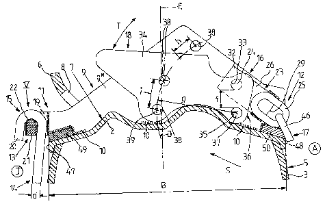
According to the invention at least one fixing bridge 9 is
provided, which is fixed to the inner circumferential
CA 02562218 2010-08-06
CA 02562218 2006-10-05
WO 2005/108125 PCT/EP2004/003634
- 9
surface 7 of the rim 2 transverse to the plane of the rim
(that runs parallel to the plane of the drawing) and extends
essentially over its width B (Figure 4). In this case, said
fixing bridge 9 is fixed as a double web to the inner
circumferential surface 7 of the rim 2 by means of welds 10.
The double web 9 has in each case a pair formed from a first
and second fixing device 11 and 12 respectively. The first
fixing device 11 facing the wheel inner side .T of the double
web 9 is provided with a first fixing element 13 for hooking
and unhooking a second fixing element 15 complementary to
the first fixing element 13 and fitted to the one end 14 of
the traction aid 1.
Furthermore, the second fixing device 12 of the double web 9
facing the wheel outer side A is provided with a coupling
device 16 for coupling and tensioning a tension element 18
fitted to the other end 17 of the traction aid 1, such that
the traction aid 1 may be tensioned transversely across the
tire 3 on the running surface 4 between both ends 11 and 12
of the fixing web 9.
As can be seen in Figures 1 to 4, the double web 9 in each
case extends through an opening 8. As can be seen, a
plurality of double webs 9 evenly distributed around the
inner circumferential surface 7 extend through
correspondingly distributed openings 8, with the illustrated
embodiment having five double webs 9 of this kind. Because
there are ten openings 8 present, a double web 9 thus
extends through every second opening 8.
CA 02562218 2006-10-05
WO 2005/108125 PCT/EP2004/003634
- 10 -
According to the invention, it can now be seen that a
separate traction aid 1 is assigned to each double web 9.
With the embodiment shown, the first fixing element 13 on
the first fixing device 11 of the double web 9 is an eye 19
and the second fixing element 15 complementary thereto on
the one end 14 of the traction aid 1 is a hook 20 that can
be hooked into the eye 19.
As is clearly shown in Figures 4 and 5, in this case it is
advantageous if the eye 19 is embodied in such a way that
its depth t arranged perpendicular to the plane of the wheel
(that corresponds to the center plane E in Figure 4) is
greater than the diameter d of the rod material of the hook
20, but its width b is somewhat greater than the width b' of
the curved part of the hook 20 (Figure 5). The result of
this is that the hook 20 can only be inserted into the eye
19 from below when rotated 900 relative to its position
shown in Figures 4 and 5, (Figure 4) and can then be hooked
onto a cross bar 21 of the eye 19 after turning back, with
this cross bar 21 being suitably rounded on its top 22
corresponding to the curve in the hook (Figure 4). This
provides for a reliable anchorage of the hook 20 in the eye
19 without the danger of a strong deflection of the tire 3,
for example if the air pressure is too low, resulting in an
automatic disengagement of the hook 20 from the eye 19.
The tension element 18 is secured at the other end 17 of the
traction aid by means of'a first pivot pin 24 that passes
through the tension element 18 on the one hand and a fitting
23 fixed to the other end 17 of the traction aid 1 on the
CA 02562218 2010-08-06
CA 02562218 2006-10-05
WO 2005/108125 PCT/EP2004/003634
- 11 -
other hand. Moreover, the fitting 23 advantageously consists
.of a chain link 25 that engages with the traction aid 1, on
both sides of which two straps 26 are welded in parallel by
means of the mutually opposite surfaces 27 and 28 of their
respective first ends 29 and 30. The other ends 31 and 32 of
the straps 26 hold between them the tension element 18 and
first pivot pin 24 which passes through corresponding first
holes 33 in the straps 26 on the one hand and the tension
element 18 on the other hand and is locked by a split pin.
With the preferred embodiment shown, the double web has two
part-webs 9' and 911 arranged at the distance m from each
other (Figure 2) and parallel to each other. To guarantee
the required distance between the part-webs 9' and 911,
spreaders 49 and 50 are welded to the two respective ends 11
and 12 of the double web 9. These spreaders also protect the
respective rim edges 47 and 48 from the hook 20 on the one
hand and the chain links 25 and 46 adjacent to the fitting
23 on the other hand.
The tension element 18 is usefully a tension lever 34 the
thickness e of which is less than the distance M between. the
part-webs 9' and 9" and that can be inserted between the
two part-webs 9' and 9".
Furthermore, the tension lever 34 can be coupled to the
part-webs 9' and 9" by means of a second pivot pin 37,
offset at a distance (f) from the first pivot pin 24
transverse to the direction of tensioning S and to the inner
circumferential surface 7, which second pivot pin 37 is
inserted in second holes 35 (Figure 4) aligned with each
CA 02562218 2006-10-05
WO 2005/108125 PCT/EP2004/003634
12 -
other in the end 36 of the tension lever 34 facing towards
the other end 17 of the traction aid 1, on the one hand and
in both part-webs 9 and 9' on the other hand and can be
split pinned (split pin 51), in such a manner that due to
the distance f between them an eccentricity of the first
pivot pin 24 exists with respect to the second pivot pin 37
and swiveling the tension lever 34 in the direction of the
arrow T, and thus in the diretion of the rim, tensions the
traction aid 1.
It is necessary that after swiveling in the direction of the
arrow T and thus tensioning the traction aid 1 (Figure 4)
the tension lever 34 is locked against the rim or double web
9 or the two part-webs 9', 911, to maintain the tension of
the traction aid 1.
For this purpose, the tension lever 34 can advantageously be
releasably locked by tensioning the traction aid against the
part-webs 9, 9'' by means of a releasable locking pin 39
that can be inserted into third holes 38 aligned with each
other, at a distance g from the second pivot pin 37 in the
longitudinal direction of the tension lever (see
longitudinal axis c in Figure 2), in the area of the tension
lever 34 facing away from the other end 17 of the traction
aid 1 on the one hand and into the two part-webs 9', 9'' on
the other hand and can be split pinned (split pin 52).
Furthermore, a plurality of third holes 38 on a circle of
rotation of the tension lever 34 around the second pivot pin
37 and at a distance (radius g) from same, arranged in the
direction of rotation (arrow T) at a distance h from each
CA 02562218 2006-10-05
WO 2005/108125 PCT/EP2004/003634
13 -
other and aligned with each other are provided to accept the
locking pin 39 in such a way that the tension lever 34 can
be locked in different tensioned positions. This enables
tolerances, for example in tire sizes or in the length of
the traction aid 1, etc., to be accommodated.
Furthermore, at least two holes 38 for the locking pin 39
can also be provided in the tension lever 34 on the same
circle of rotation D about the second pivot pin 37, with the
distance i between in each case two holes 38 in the tension
lever 34 being greater than the distance h between in each
case two holes 38 in the part-webs 9' and 9", thus
facilitating adjustments.
With the preferred embodiment shown, each traction aid 1
according to Figures 1, 3 and 6 consists of a chain sling 42
held apart by two bar-type spreaders 41 arranged in the
circumferential direction of the tire 3 at both sides on the
edges 40 of same in such a manner that in each case two
chain sling sections 43 and 44 are tensioned over the
running surface 45 of the tire 3 and spaced apart from each
other at a distance k corresponding to the length of the
spreaders 41.
It is of course obvious that the snow chain does not
necessarily have to be a type of chain net in the manner
described, but can also be a simple chain tensioned
transversely over the running surface of the tire,
especially where the ground traction is not so bad that the
use of a chain net with a corresponding plurality of links
appears necessary to generate greater adhesion or friction.
CA 02562218 2006-10-05
WO 2005/108125 PCT/EP2004/003634
14 -
Just one or more single chains could perhaps also be
sufficient to get the vehicle thus -equipped back in
operation.