Language selection

Search

Patent 2562592 Summary

Third-party information liability

Some of the information on this Web page has been provided by external sources. The Government of Canada is not responsible for the accuracy, reliability or currency of the information supplied by external sources. Users wishing to rely upon this information should consult directly with the source of the information. Content provided by external sources is not subject to official languages, privacy and accessibility requirements.

Claims and Abstract availability

Any discrepancies in the text and image of the Claims and Abstract are due to differing posting times. Text of the Claims and Abstract are posted:

  • At the time the application is open to public inspection;
  • At the time of issue of the patent (grant).
(12) Patent Application: (11) CA 2562592
(54) English Title: METHOD AND SYSTEM FOR HANDLING MULTICAST EVENT CONTROL SYMBOLS
(54) French Title: METHODE ET SYSTEME PERMETTANT DE TRAITER DES SYMBOLES DE CONTROLE D'EVENEMENT A DIFFUSION SELECTIVE
Status: Deemed Abandoned and Beyond the Period of Reinstatement - Pending Response to Notice of Disregarded Communication
Bibliographic Data
(51) International Patent Classification (IPC):
  • H04L 07/04 (2006.01)
  • H04L 12/18 (2006.01)
(72) Inventors :
  • WOOD, BARRY (Canada)
  • GAGNON, STEPHANE (Canada)
(73) Owners :
  • IDT CANADA INC.
(71) Applicants :
  • IDT CANADA INC. (Canada)
(74) Agent: MARKS & CLERK
(74) Associate agent:
(45) Issued:
(22) Filed Date: 2006-10-05
(41) Open to Public Inspection: 2007-05-28
Examination requested: 2011-10-04
Availability of licence: N/A
Dedicated to the Public: N/A
(25) Language of filing: English

Patent Cooperation Treaty (PCT): No

(30) Application Priority Data:
Application No. Country/Territory Date
60/740,400 (United States of America) 2005-11-28

Abstracts

English Abstract


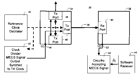
A packet switching system comprises a first switch and a second switch. The
first
switch includes a first receive port, a first plurality of transmit ports, a
first switch
fabric, a first reference clock signal input and a first multicast control
symbol
input/output port coupled to the first plurality of transmit ports for
inputting a
multicast control signal to be transmitted. The second switch includes a
second
receive port, a second plurality of transmit ports, a second switch fabric, a
second
reference clock signal input and a second multicast control symbol
input/output port
coupled to the second receive port for outputting a received multicast control
symbol.
In operation, a multicast control symbol is generated in hardware synchronized
with a
reference clock signal and the multicast control symbol directly to the first
plurality of
transmit ports.


Claims

Note: Claims are shown in the official language in which they were submitted.


7
What is claimed is:
1. A packet switching system comprising;
a receive port;
a plurality of transmit ports;
a switch fabric for selectively coupling the receive port to the transmit
ports;
a reference clock signal input; and
a multicast control symbol input/output port coupled to the receive port for
outputting a received multicast control symbol and to the plurality of
transmit ports
for inputting a control signal to be transmitted; whereby multicast control
symbols are
synchronized to the reference clock signal.
2. A system as claimed in claim 1 including a multicast control symbol
generator
coupled to the control symbol input/output port.
3. A system as claimed in claim 2 including a reference clock coupled to the
reference clock input.
4. A system as claimed in claim 2 wherein the multicast control symbol
generator includes a clock input for coupling to a reference clock.
5. A system as claimed in claim 2 wherein the multicast control symbol
generator does not include a clock input for coupling to a reference clock
6. A system as claimed in claim 1 including a multicast control symbol
acceptor
coupled to the multicast control symbol input/output port.
7. A system as claimed in claim 6 including a software receiver coupled to the
multicast control symbol acceptor.

8
8. A system as claimed in claim 6 including a hardware receiver coupled to the
multicast control symbol acceptor.
9. A system as claimed in claim 1 including a software multicast control
symbol
originator coupled to the receive port.
10. A packet switching system comprising;
a first switch including a first receive port, a first plurality of transmit
ports, a
first switch fabric for selectively coupling the receive port to the transmit
ports, a first
reference clock signal input and a first multicast control symbol input/output
port
coupled to the first plurality of transmit ports for inputting a multicast
control signal
to be transmitted; and
at least one second switch including a second receive port, a second plurality
of transmit ports, a second switch fabric for selectively coupling the receive
port to
the transmit ports, a second reference clock signal input and a second
multicast
control symbol input/output port coupled to the second receive port for
outputting a
received multicast control symbol;
whereby multicast control symbols are synchronized to a reference clock
signal.
11. A system as claimed in claim 10 including a multicast control symbol
generator coupled to the first multicast control symbol input/output port.
12. A system as claimed in claim 10 including a reference clock coupled to the
first reference clock input.
13. A system as claimed in claim 10 wherein the control symbol generator
includes a clock input for coupling to a reference clock.
14. A system as claimed in claim 10 including a control symbol acceptor
coupled
to the second multicast control symbol input/output port.

9
15. A system as claimed in claim 14 including a software receiver coupled to
the
multicast control symbol acceptor.
16. A system as claimed in claim 10 including a software multicast control
symbol
originator coupled to the first receive port.
17. A method of operating a packet switching system comprising a first switch
including a first receive port, a first plurality of transmit ports, a first
switch fabric for
selectively coupling the receive port to the transmit ports, a first reference
clock signal
input and a first multicast control symbol input/output port coupled to the
first
plurality of transmit ports for inputting a control signal to be transmitted;
and at least
one second switch including a second receive port, a second plurality of
transmit
ports, a second switch fabric for selectively coupling the receive port to the
transmit
ports, a second reference clock signal input and a second multicast control
symbol
input/output port coupled to the second receive port for outputting a received
multicast control symbol, said method comprising the steps of:
generating a reference clock signal;
generating a multicast control symbol in dependence upon the reference clock
signal;
coupling the multicast control symbol directly to the first plurality of
transmit
ports; and
transmitting the multicast control symbol to the second receive port.
18. A method as claimed in claim 17 including the step of synchronizing the
multicast control symbol to the reference clock signal.
19. A method as claimed in claim 17 wherein the step of transmitting the
multicast
control symbol uses the reference clock signal.
20. A method as claimed in claim 17 including the step of receiving the
multicast
control symbol at the second receive port.

10
21. A method as claimed in claim 17 where the transmission of the multicast
control symbol is delayed to ensure that no RapidIO protocol artifacts induce
jitter in
the propagation of the multicast control symbol
22. A method as claimed in claim 20 including the step of directly coupling
the
multicast control symbol via the second input/output port to a multicast
control
symbol acceptor.
23. A method as claimed in claim 22 including the step of receiving in
software
the multicast control symbol from the multicast control symbol acceptor.
24. A method as claimed in claim 22 including the step of receiving in
hardware
the multicast control symbol from the multicast control symbol acceptor.

Description

Note: Descriptions are shown in the official language in which they were submitted.


CA 02562592 2006-10-05
METHOD AND SYSTEM FOR HANDLING MULTICAST EVENT
CONTROL SYMBOLS
Field of the Invention
The present invention relates to a method and switch for handling multicast
event control symbols.
Background of the Invention
Multicast Event Control Symbols (MECS) are used to distribute regularly
occurring events throughout a RapidlO system. For example, notification that a
frame
of antenna data has been completely received, distribution of an accurate real
time
clock, or a'heartbeat' for determining system health. RapidlO is a trademark
of the
RapidIO Trade Association, a non-profit corporation controlled by its members,
directs the development and drives the adoption of the RapidlO architecture.
Referring to Fig. I there is illustrated a known packet switching system. The
packet switching system 10 uses the RapidIO protocol and includes a software
Multicast Control Symbol (MECS) Originator 12, a first node 14, a second node
16,
coupled to the first via a link 18 and a software Multicast Control Symbol
(MECS)
Receiver 20.
RapidlO has defined a standard Multicast Control Symbol (MECS) of four
bytes. A MECS is used to signal events in a system, for example a time tick.
The
implementation of MECS is vendor specific.
In operation, originating software 12 originates the MECS at a rate determined
by an interrupt. When a RapidlO port receives a MECS, it signals all other
ports of
the fact that a MECS has been received. The receiving port forwards the symbol
to
the other ports. For example, the MECS is replicated by hardware by the node
14 to

CA 02562592 2006-10-05
2
all receiving nodes 16. Receiving software 20 is notified of the MECS
reception by
the interrupt.
The standard method for generating and distributing Multicast Event Control
Symbols (MECS) requires that all of the ports on a switch support two signals:
='Received an MECS' output signal - indicates that a MECS was received on
the port
='Transmit MECS' input signal - the wired 'OR' of the 'Received an MECS'
signal for all other ports.
Each port has a standard control value that determines whether assertion of
the
'Transmit MECS' signal will cause a MECS to be transmitted.
In the Rapid 10 standard, the generation and reception of Multicast Event
Control Symbols (MECS) is assumed to be done by software. This is not optimal,
for
the following reasons.
= The generation of Multicast Event Control symbols by software consumes
significant system compute resources. For example, distributing a real time
clock that has a period of 1 millisecond requires that the generating software
process 1000 time based interrupts per second, and that the receiving software
process 1000 interrupts per second. This interrupt processing can consume
upwards of 10% of each processors compute capacity.
= Generation and reception of multicast event control symbols by software
results in a wide variation in the actual times that the multicast event
control
symbols are generated, and received, due to varying software execution times
on a processor.
Because of potential negative impact on processor resources, expanding use of
multicast event control symbols (MECS) beyond the intended timing events is

CA 02562592 2006-10-05
3
severely limited. An additional problem is that no other control mechanism was
defined in the standard.
Summary of the Invention
An object of the present invention is to provide an improved method and
system for handling multicast event control symbols (MECS).
The present disclosure specifies an optimum method for generating multicast
event control symbols using hardware. This method provides a very efficient
implementation of multicast event control symbol propagation, as well as a
means for
signaling the occurrence of multicast event control symbols to hardware
appliances.
The method of hardware generation/propagation of multicast event control
symbols
results in low jitter for the creation/propagation of multicast event control
symbols,
and eliminates any software overhead required for generation.
In accordance with an aspect of the present invention there is provided a
packet switching system comprising a receive port, a plurality of transmit
ports, a
switch fabric for selectively coupling the receive port to the transmit ports,
a reference
clock signal input and a multicast control symbol input/output port coupled to
the
receive port for outputting a received multicast control symbol and to the
plurality of
transmit ports for inputting a control signal to be transmitted; whereby
multicast
control symbols are synchronized to the reference clock signal.
In accordance with a further aspect of the present invention there is provided
a
packet switching system comprising a first switch including a first receive
port, a first
plurality of transmit ports, a first switch fabric for selectively coupling
the receive
port to the transmit ports, a first reference clock signal input and a first
multicast
control symbol input/output port coupled to the first receive port for
outputting a
received multicast control symbol and to the first plurality of transmit ports
for
inputting a multicast control signal to be transmitted and at least one second
switch
including a second receive port, a second plurality of transmit ports, a
second switch
fabric for selectively coupling the receive port to the transmit ports, a
second
reference clock signal input and a second multicast control symbol
input/output port

CA 02562592 2006-10-05
4
coupled to the second receive port for outputting a received multicast control
symbol
and to the second plurality of transmit ports for inputting a control signal
to be
transmitted; whereby multicast control symbols are synchronized to a reference
clock
signal.
In accordance with another aspect of the present invention there is provided a
method of operating a packet switching system comprising a first switch
including a
first receive port, a first plurality of transmit ports, a first switch fabric
for selectively
coupling the receive port to the transmit ports, a first reference clock
signal input and
a first multicast control symbol input/output port coupled to the first
receive port for
outputting a received multicast control symbol and to the first plurality of
transmit
ports for inputting a control signal to be transmitted; and at least one
second switch
including a second receive port, a second plurality of transmit ports, a
second switch
fabric for selectively coupling the receive port to the transmit ports, a
second
reference clock signal input and a second multicast control symbol
input/output port
coupled to the second receive port for outputting a received multicast control
symbol
and to the second plurality of transmit ports for inputting a control signal
to be
transmitted, said method comprising the steps of generating a reference clock
signal,
generating a multicast control symbol in dependence upon the reference clock
signal,
coupling the multicast control symbol directly to the first plurality of
transmit ports
and transmitting the multicast control symbol to the second receive port.
Brief Description of the Drawings
The present invention will be further understood from the following detailed
description with reference to the drawings in which:
Fig. 1 illustrates a known packet switching system;
Fig. 2 illustrates a packet switching system in accordance with an embodiment
of the
present invention; and
Fig. 3 illustrates a packet switching system in accordance with another
embodiment
of the present invention.

CA 02562592 2006-10-05
Detailed Description of the Preferred Embodiment
Referring to Fig. 2 there is illustrated a packet switching system for
handling
multicast event control symbols in accordance with an embodiment of the
present
5 invention. The packet switching system 30 includes a reference clock 32, a
first
packet switch 34, a second packet switch 36 coupled 38 with the first packet
switch
34, a MECS symbol generator 40, a MECS acceptor 42 and a software receiver.
The
MECS symbol generator 40 is coupled to the first packet switch 34 via a first
input/output 46. The reference clock 32 is coupled to transmitter ports 48 of
first
packet switch 34 . A receiver port 50 of second packet switch 36 is coupled to
the
MECS acceptor 42 via a second input/output 52.
Referring to Fig. there is illustrated a packet switching system for handling
multicast event control symbols in accordance with another embodiment of the
present invention. The packet switching system 30 includes a reference clock
32, a
first packet switch 34, a second packet switch 36 coupled 38 with the first
packet
switch 34, a MECS symbol generator 40, a MECS acceptor 58 and a hardware
receiver 59, in the form of a framer field programmable gate array (FPGA). The
MECS symbol generator 40 is coupled to the first packet switch 34 via a first
input/output 46. The reference clock 32 is coupled to transmitter ports 48 of
first
packet switch 34 . A receiver port 50 of second packet switch 36 is coupled to
the
MECS acceptor 58 via a second input/output 52.
The present embodiments of the invention leverages the existing infrastructure
for generating and distributing MECS. The present embodiment adds two external
signals to the standard method; namely:
='HW Request MECS' external input signal - externally driven trigger
to transmit an MECS
='HW Received an MECS' external output signal - indicates that an
MECS has been received

CA 02562592 2006-10-05
6
The 'HW Request MECS' signal is added to the signal's OR'ed together to
create the 'Transmit MECS' input signal. The 'HW Received an MECS' output is
the
wired OR of all ports 'Received and MECS' signals.
In order to transmit regular events with minimal jitter, the 'HW Request
MECS' signal is driven synchronously with the reference clock 32 used to drive
the
transmitter 46 on every link. The standard RapidlO capability, which allows
MECS
to be transmitted embedded within packets is incorporated into the design to
ensure
that MECS will be transmitted at the time the 'HW Request MECS' signal is
asserted.
Additional refinements must be used to eliminate the variation in transmission
intervals associated with the propagation of a RapidlO MECS. Variation in
transmission intervals occur because of the needs of the RapidlO protocol. The
RapidlO specification requires that an idle sequence be transmitted at a
specified
interval to ensure continued correct operation of the RapidlO link. RapidlO
also
requires that a buffer status control symbol be transmitted within a specified
interval.
In order to avoid transmission of an idle sequence and a buffer status control
symbol interfering with transmission of the RapidlO MECS, a change is made to
the
standard implementation of MECS. Instead of transmitting the MECS as soon as
possible upon reception of a'Transmit MECS' request, the transmission is
delayed by
a period of time sufficient to transmit an idle sequence and a buffer status
control
symbol. If an idle sequence and/or a buffer status control symbol need to be
transmitted, they can be transmitted at that point. This eliminates the
variability in
time of the transmission of the MECS, thus resulting in completely predictable
transmission of the MECS throughout a RapidlO system.
Numerous other modifications, variations and adaptations may be made to the
particular embodiments of the invention described above without departing from
the
scope of the invention as defined in the claims.

Representative Drawing
A single figure which represents the drawing illustrating the invention.
Administrative Status

2024-08-01:As part of the Next Generation Patents (NGP) transition, the Canadian Patents Database (CPD) now contains a more detailed Event History, which replicates the Event Log of our new back-office solution.

Please note that "Inactive:" events refers to events no longer in use in our new back-office solution.

For a clearer understanding of the status of the application/patent presented on this page, the site Disclaimer , as well as the definitions for Patent , Event History , Maintenance Fee  and Payment History  should be consulted.

Event History

Description Date
Inactive: IPC expired 2022-01-01
Application Not Reinstated by Deadline 2015-06-03
Inactive: Dead - No reply to s.30(2) Rules requisition 2015-06-03
Deemed Abandoned - Failure to Respond to Maintenance Fee Notice 2014-10-06
Inactive: Abandoned - No reply to s.30(2) Rules requisition 2014-06-03
Inactive: Abandoned - No reply to s.29 Rules requisition 2014-06-03
Inactive: S.29 Rules - Examiner requisition 2013-12-03
Inactive: S.30(2) Rules - Examiner requisition 2013-12-03
Inactive: Report - No QC 2013-11-21
Inactive: IPC assigned 2013-10-22
Inactive: First IPC assigned 2013-10-22
Inactive: IPC expired 2013-01-01
Inactive: IPC removed 2012-12-31
Letter Sent 2011-10-18
Request for Examination Received 2011-10-04
Amendment Received - Voluntary Amendment 2011-10-04
All Requirements for Examination Determined Compliant 2011-10-04
Request for Examination Requirements Determined Compliant 2011-10-04
Revocation of Agent Requirements Determined Compliant 2010-04-29
Inactive: Office letter 2010-04-29
Appointment of Agent Requirements Determined Compliant 2010-04-29
Letter Sent 2010-04-08
Appointment of Agent Request 2010-03-25
Revocation of Agent Request 2010-03-25
Application Published (Open to Public Inspection) 2007-05-28
Inactive: Cover page published 2007-05-27
Inactive: IPC assigned 2006-12-28
Inactive: First IPC assigned 2006-12-28
Inactive: Filing certificate - No RFE (English) 2006-11-03
Letter Sent 2006-11-03
Application Received - Regular National 2006-11-03

Abandonment History

Abandonment Date Reason Reinstatement Date
2014-10-06

Maintenance Fee

The last payment was received on 2013-09-27

Note : If the full payment has not been received on or before the date indicated, a further fee may be required which may be one of the following

  • the reinstatement fee;
  • the late payment fee; or
  • additional fee to reverse deemed expiry.

Patent fees are adjusted on the 1st of January every year. The amounts above are the current amounts if received by December 31 of the current year.
Please refer to the CIPO Patent Fees web page to see all current fee amounts.

Owners on Record

Note: Records showing the ownership history in alphabetical order.

Current Owners on Record
IDT CANADA INC.
Past Owners on Record
BARRY WOOD
STEPHANE GAGNON
Past Owners that do not appear in the "Owners on Record" listing will appear in other documentation within the application.
Documents

To view selected files, please enter reCAPTCHA code :


To view images, click a link in the Document Description column. To download the documents, select one or more checkboxes in the first column and then click the "Download Selected in PDF format (Zip Archive)" or the "Download Selected as Single PDF" button.

List of published and non-published patent-specific documents on the CPD .

If you have any difficulty accessing content, you can call the Client Service Centre at 1-866-997-1936 or send them an e-mail at CIPO Client Service Centre.


Document
Description 
Date
(yyyy-mm-dd) 
Number of pages   Size of Image (KB) 
Description 2006-10-04 6 250
Abstract 2006-10-04 1 20
Claims 2006-10-04 4 116
Drawings 2006-10-04 3 43
Representative drawing 2007-05-01 1 8
Courtesy - Certificate of registration (related document(s)) 2006-11-02 1 106
Filing Certificate (English) 2006-11-02 1 158
Reminder of maintenance fee due 2008-06-08 1 113
Reminder - Request for Examination 2011-06-06 1 120
Acknowledgement of Request for Examination 2011-10-17 1 176
Courtesy - Abandonment Letter (R30(2)) 2014-07-28 1 166
Courtesy - Abandonment Letter (R29) 2014-07-28 1 166
Courtesy - Abandonment Letter (Maintenance Fee) 2014-11-30 1 172
Fees 2011-10-02 1 155
Fees 2008-09-04 1 41
Fees 2009-09-21 1 39
Correspondence 2010-03-24 2 80
Correspondence 2010-04-28 1 14
Correspondence 2010-04-28 1 16