Language selection

Search

Patent 2562629 Summary

Third-party information liability

Some of the information on this Web page has been provided by external sources. The Government of Canada is not responsible for the accuracy, reliability or currency of the information supplied by external sources. Users wishing to rely upon this information should consult directly with the source of the information. Content provided by external sources is not subject to official languages, privacy and accessibility requirements.

Claims and Abstract availability

Any discrepancies in the text and image of the Claims and Abstract are due to differing posting times. Text of the Claims and Abstract are posted:

  • At the time the application is open to public inspection;
  • At the time of issue of the patent (grant).
(12) Patent: (11) CA 2562629
(54) English Title: FUEL FILTER FOR DIESEL INTERNAL COMBUSTION ENGINES
(54) French Title: FILTRE A CARBURANT POUR DES MOTEURS DIESEL A COMBUSTION INTERNE
Status: Granted and Issued
Bibliographic Data
(51) International Patent Classification (IPC):
  • B01D 27/10 (2006.01)
  • B01D 35/143 (2006.01)
  • B01D 35/18 (2006.01)
(72) Inventors :
  • GIRONDI, GIORGIO (Italy)
(73) Owners :
  • UFI FILTERS S.P.A.
(71) Applicants :
  • UFI FILTERS S.P.A. (Italy)
(74) Agent: ROBIC AGENCE PI S.E.C./ROBIC IP AGENCY LP
(74) Associate agent:
(45) Issued: 2012-07-31
(86) PCT Filing Date: 2005-05-13
(87) Open to Public Inspection: 2005-12-15
Examination requested: 2010-04-08
Availability of licence: N/A
Dedicated to the Public: N/A
(25) Language of filing: English

Patent Cooperation Treaty (PCT): Yes
(86) PCT Filing Number: PCT/EP2005/005386
(87) International Publication Number: WO 2005118102
(85) National Entry: 2006-10-11

(30) Application Priority Data:
Application No. Country/Territory Date
RE2004A000066 (Italy) 2004-06-01

Abstracts

English Abstract


For diesel internal combustion engines, an improved filter unit comprising an
outer casing (2, 3) the interior of which is separated by a filtering baffle
(7) into two separate chambers to which a fuel inlet conduit (4) and a fuel
outlet conduit (5) are connected respectively, with said casing there being
associated a device (12) provided with sensors (16) for measuring certain
characteristic parameters for correct engine operation.


French Abstract

L'invention concerne des moteurs diesel à combustion interne, une unité de filtre améliorée comprenant un logement (2, 3) extérieur, dont l'intérieur est séparé par une cloison filtre (7) en deux chambres séparées, auxquelles un conduit d'entrée (4) de carburant et un conduit de sortie (5) de carburant sont reliés respectivement. Un dispositif (12) doté de détecteurs (16) destinés à mesurer des paramètres caractéristiques de fonctionnement normal du moteur est associé audit logement.

Claims

Note: Claims are shown in the official language in which they were submitted.

6
WHAT IS CLAIMED IS:
1. For diesel internal combustion engines, a disposable filter unit (1)
comprising
an outer casing (2) the interior of which is separated by a filtering baffle
(7) into a
first chamber (9) and a second chamber (10) to which a fuel inlet conduit (4)
and a
fuel outlet conduit (5) are connected respectively, characterised by
comprising a
removable device (12) received within the casing (2) through a tubular hole
(20),
coaxial to the baffle (7) in a position opposite to said inlet and outlet
conduits (4, 5),
said device (12) having an elongated shape internally comprising two separate
portions, a first portion (13) positioned entirely inside the first chamber
(9) and a
second portion (14) positioned inside the second chamber (10) near the tubular
hole
(20), the first portion (13) housing sensors (16, 18) for measuring certain
characteristic parameters for correct engine operation, and the second portion
(14)
housing water level sensor (24) for measuring the level of water which
accumulates
at the bottom of the casing (2), all said sensors (16, 18, 24) being
permanently
connected to electronic control means (17) which are incorporated into said
removable device (12) and are permanently connected to control means of the
engine which the filter (1) is applied to.
2. A filter unit (1) as claimed in claim 1, characterised in that a seal
gasket (101)
is interposed between said device (12) and said filtering baffle (7).
3. A filter unit (1) as claimed in claim 1, characterised in that said device
(12) is
shaped as a shaft with different cross-sections.
4. A filter unit (1) as claimed in claim 3, characterised in that said first
portion
(13) presents in its outer surface at least one aperture (15) for fuel entry.
5. A filter unit (1) as claimed in claim 4, characterised in that said
electronic
control means comprise an electronic control card (17).

7
6. A filter unit (1) as claimed in claim 1, characterised in that said sensors
(16,
18) for measuring certain characteristic parameters for correct engine
operation
comprise a temperature measurements device (16) and a heating device (18).
7. A filter unit (1) as claimed in claim 1, characterised in that said water
level
sensor (24) comprises two inductive electrodes (24) which branch from the
outer
surface of the second portion (14) of the device (12).

Description

Note: Descriptions are shown in the official language in which they were submitted.


CA 02562629 2011-12-23
1
FUEL FILTER FOR DIESEL INTERNAL COMBUSTION ENGINES
TECHNICAL FIELD
The present invention relates to a filter unit to be associated with diesel
internal
combustion engines, and in particular to a filter unit provided with a
combined
device for measuring certain parameters which enable functional
characteristics of
the engine to be monitored and/or adjusted.
PRIOR ART
For their correct operation, modern diesel engines require numerous parameters
to
be measured, such as the diesel fuel temperature, or possible water presence
in the
fuel filter.
The known art teaches that some of the parameters to be measured are measured
by a plurality of individual devices associated with the fuel filter. For
example,
devices are known for sensing water presence in the filter, devices for
measuring
fuel temperature, and devices for regulating the fuel temperature within the
filter to
facilitate engine start under unfavourable climatic conditions.
All these devices are currently associated individually with the filter and
are often
composed of disposable measurement and/or checking elements, i.e. which are
replaced together with the filter and are therefore necessarily elements of
low
quality.
The document DE 20115220 U1 discloses a heating unit to be associated to a
fuel
filter unit.
The heating unit comprises a the inlet passage for the fuel, an heating means
contained in an elongated tube to be inserted into the casing of the filter
unit, the

CA 02562629 2011-12-23
2
elongated tube having a head intended to be externally fixed to the casing of
the
filter unit for containing electronic control means of the heating means.
The electric control means is responsive to sensors located within the tube.
The device of DE 20115220 presents some drawbacks because it extends over the
overall dimensions of the filter unit, and requests a modification of the
design of the
filter unit to be associated therewith.
Specifically, on replacing the filter, the user has to remove all the
connection plugs
of each sensor of the individual devices to then reconnect them to the sensors
installed on the new filter. In view of the large number of sensors, all this
represents
a considerable time, and a possible source of connection errors.
There is therefore a need for a filter unit provided with a combined device
which
comprises all the sensors required to measure engine operating parameters and
is
simple to install on replacing the filter.
DISCLOSURE OF THE INVENTION
The object of the present invention is to satisfy said requirement within the
context
of a simple, rational and low-cost solution.
The invention attains said object by virtue of a disposable filter unit for
diesel
internal combustion engines comprising an outer casing the interior of which
is
separated by a filtering baffle into a first chamber and a second chamber to
which a
fuel inlet conduit and a fuel outlet conduit are connected respectively,
characterised
by comprising a removable device received within the casing through a tubular
hole,
coaxial to the baffle in a position opposite to said inlet and outlet
conduits, said
device having an elongated shape internally comprising two separate portions,
a
first portion positioned entirely inside the first chamber and a second
portion

CA 02562629 2011-12-23
3
positioned inside the second chamber near the tubular hole, the first portion
housing
sensors for measuring certain characteristic parameters for correct engine
operation, and the second portion housing water level sensor for measuring the
level of water which accumulates at the bottom of the casing, all said sensors
being
permanently connected to electronic control means which are incorporated into
said
removable device and are permanently connected to control means of the engine
which the filter is applied to.
Specifically the invention provides, for diesel internal combustion engines, a
filter
unit comprising an outer casing the interior of which is separated by a
filtering baffle
into two separate chambers to which a fuel inlet conduit and a fuel outlet
conduit are
connected respectively, in the interior of said casing there being housed a
device,
removable from outside the casing, for measuring certain characteristic
parameters
for correct engine operation.
BRIEF DESCRIPTION OF THE DRAWINGS
The characteristics and the constructional merits of the invention will be
more
apparent from the ensuing description given with reference to the figures of
the
accompanying drawings which illustrate a particular preferred embodiment by
way
of non-limiting example.
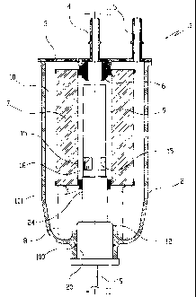
Figure 1 is a side section through the filter unit of the invention;
Figure 2 is a schematic section, taken on the line II-II of Figure 1, through
the
combined device with which the unit of the invention is provided;
Figure 3 shows the section III-III of Figure 2.
BEST MODE FOR CARRYING OUT THE INVENTION
Said figures show the filter unit 1, comprising a cup-shaped outer casing 2
closed
upperly by a cover 3 on which a fuel inlet conduit 4 and a fuel outlet conduit
5 are

CA 02562629 2011-12-23
3a
positioned.
The inlet conduit 4, positioned centrally, extends below the cover to define a
stem 6,
the function of which will be clarified hereinafter.
The interior of the casing 2 houses a toroidal filtering baffle 7 supported
between a
lower end 8 and the stem 6 branching from the cover 3.
Said filtering baffle 7 divides the interior of the casing 2 substantially
into two
separate chambers 9 and 10, of which the first, 9, is connected to the inlet
conduit 4
for the fuel to be filtered, and the second, 10, is connected to the outlet
conduit 5 for
the filtered fuel.
The casing 2 lowerly presents a tubular hole 20 which receives a device 12
carrying
sensors for measuring a certain number of parameters necessary for correct
operation of the engine, not shown, provided with the filter unit 1.
In the illustrated embodiment, the device 12 contains a temperature
measurement
sensor, a fuel heating device, and a sensor for sensing water collected on the
base
of the casing 2.
With particular reference to Figures 2 and 3, the device 12 is shaped
externally as a
shaft of differing cross-section which is inserted under

CA 02562629 2006-10-11
WO 2005/118102 PCT/EP2005/005386
4
sealed conditions, by virtue of gaskets 100 and 101, into the casing 2 and
the filtering baffle 7, and extends nearly as far as the stem 6. Said device
12 and the filtering baffle 7 then together define said chambers 9 and 10.
The device 12 is made rigid with the casing 2 by a usual fixing means, not
shown, such as a peg or a set screw.
Internally the device 12 is hollow and divided into two separate portions, of
which the upper portion 13 is positioned inside the chamber 9 and
the underlying lower portion 14 is positioned inside the chamber 10.
The upper portion 13 is upperly open, being in the form of a cup, and
io presents two rectangular apertures 15 in its lateral surface.
The portion 13 houses in its interior, in proximity to said apertures 15, a
sensor 16 for measuring the fuel temperature, said sensor being
connected to an electronic control card 17 housed in the lower portion 14
of the device.
The upper portion 13 also houses in its interior a heating device 18, of
known type, also connected to said electronic control card 17.
The device 12 also comprises sensors which sense the presence of an
excessive quantity of water accumulated in the bottom of the casing 1. In
the illustrated embodiment said sensors comprise two inductive electrodes
24 which branch from the outer surface of the lower portion 14 of the
device 12 and are connected to said control card 17.
The control card 17 is connected to the vehicle control system by a data
transmission cable 19.
This integration of all sensors within the device 12 enables the filter to be
easily and quickly replaced. For this purpose, after removing the fixing
means, not shown, the operator has merely to withdraw the device 12

CA 02562629 2006-10-11
WO 2005/118102 PCT/EP2005/005386
from the casing 2 and reinsert it into the casing of the new filter unit,
hence enabling better quality components to be used.
It should also be noted that the shaft-like construction of the device 12
offers the further advantage that no sensor components are disposed of
5 as happens in the known art, so considerably reducing the overall cost of
the filter unit.
Finally, in other embodiments the device 12 can incorporate sensors
different in terms of number and/or function from those previously
described.

Representative Drawing
A single figure which represents the drawing illustrating the invention.
Administrative Status

2024-08-01:As part of the Next Generation Patents (NGP) transition, the Canadian Patents Database (CPD) now contains a more detailed Event History, which replicates the Event Log of our new back-office solution.

Please note that "Inactive:" events refers to events no longer in use in our new back-office solution.

For a clearer understanding of the status of the application/patent presented on this page, the site Disclaimer , as well as the definitions for Patent , Event History , Maintenance Fee  and Payment History  should be consulted.

Event History

Description Date
Letter Sent 2024-05-13
Inactive: COVID 19 - Deadline extended 2020-04-28
Common Representative Appointed 2019-10-30
Change of Address or Method of Correspondence Request Received 2018-12-04
Grant by Issuance 2012-07-31
Inactive: Cover page published 2012-07-30
Pre-grant 2012-05-15
Inactive: Final fee received 2012-05-15
Notice of Allowance is Issued 2012-02-09
Letter Sent 2012-02-09
Notice of Allowance is Issued 2012-02-09
Inactive: Approved for allowance (AFA) 2012-02-01
Amendment Received - Voluntary Amendment 2011-12-23
Inactive: S.30(2) Rules - Examiner requisition 2011-09-20
Inactive: Correspondence - MF 2010-08-10
Letter Sent 2010-04-26
Request for Examination Requirements Determined Compliant 2010-04-08
All Requirements for Examination Determined Compliant 2010-04-08
Request for Examination Received 2010-04-08
Inactive: IPRP received 2008-02-13
Letter Sent 2007-03-22
Inactive: Single transfer 2007-01-31
Inactive: Courtesy letter - Evidence 2006-12-12
Inactive: Cover page published 2006-12-08
Inactive: Notice - National entry - No RFE 2006-12-05
Application Received - PCT 2006-11-03
National Entry Requirements Determined Compliant 2006-10-11
Application Published (Open to Public Inspection) 2005-12-15

Abandonment History

There is no abandonment history.

Maintenance Fee

The last payment was received on 2012-04-23

Note : If the full payment has not been received on or before the date indicated, a further fee may be required which may be one of the following

  • the reinstatement fee;
  • the late payment fee; or
  • additional fee to reverse deemed expiry.

Patent fees are adjusted on the 1st of January every year. The amounts above are the current amounts if received by December 31 of the current year.
Please refer to the CIPO Patent Fees web page to see all current fee amounts.

Owners on Record

Note: Records showing the ownership history in alphabetical order.

Current Owners on Record
UFI FILTERS S.P.A.
Past Owners on Record
GIORGIO GIRONDI
Past Owners that do not appear in the "Owners on Record" listing will appear in other documentation within the application.
Documents

To view selected files, please enter reCAPTCHA code :


To view images, click a link in the Document Description column. To download the documents, select one or more checkboxes in the first column and then click the "Download Selected in PDF format (Zip Archive)" or the "Download Selected as Single PDF" button.

List of published and non-published patent-specific documents on the CPD .

If you have any difficulty accessing content, you can call the Client Service Centre at 1-866-997-1936 or send them an e-mail at CIPO Client Service Centre.


Document
Description 
Date
(yyyy-mm-dd) 
Number of pages   Size of Image (KB) 
Description 2006-10-10 5 156
Abstract 2006-10-10 2 89
Drawings 2006-10-10 2 73
Claims 2006-10-10 2 47
Representative drawing 2006-12-06 1 19
Claims 2006-10-12 2 62
Description 2006-10-12 7 244
Description 2011-12-22 6 202
Drawings 2011-12-22 2 66
Claims 2011-12-22 2 55
Representative drawing 2012-07-08 1 19
Commissioner's Notice - Maintenance Fee for a Patent Not Paid 2024-06-24 1 522
Notice of National Entry 2006-12-04 1 194
Reminder of maintenance fee due 2007-01-15 1 111
Courtesy - Certificate of registration (related document(s)) 2007-03-21 1 105
Reminder - Request for Examination 2010-01-13 1 125
Acknowledgement of Request for Examination 2010-04-25 1 177
Commissioner's Notice - Application Found Allowable 2012-02-08 1 162
PCT 2006-10-10 5 149
Correspondence 2006-12-04 1 27
Fees 2007-04-17 1 41
PCT 2006-10-12 10 345
Fees 2008-04-20 1 42
Fees 2009-05-03 1 53
Fees 2010-04-26 1 55
Correspondence 2010-08-09 1 45
Fees 2011-04-12 1 50
Correspondence 2012-02-08 1 77
Correspondence 2012-05-14 2 58