Note: Descriptions are shown in the official language in which they were submitted.
CA 02562819 2006-10-06
METHODS AND SYSTEMS FOR DELIVERING LOST CIRCULATION
MATERIAL INTO DRILLING PITS
FIELD
The present application relates to lost circulation materials and, more
particularly, to methods and systems for delivering a quantity of lost
circulation
materials.
BACKGROUND
Drilling wells to recover oil and gas typically requires introducing a
drilling
fluid into the well bore and recirculating the drilling fluid up and out of
the well bore
to lubricate the drilling components, such as the drill string and drill bit,
and to
maintain the integrity of the well bore during operation of the drill. As the
drilling
fluid is recirculated up the well bore, the fluid acts as a sealant to keep
the walls of
the well bore in place, which, among other things, allows the drill pipe to be
raised
or lowered without obstruction and facilitates removal of drilled material
from the
well bore.
Lost circulation materials, such as cottonseed hulls, cedar fiber, paper,
cottonseed burrs, sawdust, cellophane, calcium carbonate and phenolic plastic,
are
used as additives in the drilling fluid to fill fissures, porous or fractured
formations,
or other undesirable subterranean characteristics existing or formed in the
side walls
of the well bore. Filling the voids in the well bore wall with lost
circulation material
helps to prevent the recirculating drilling fluid from filling the voids,
losing drilling
fluid, and ultimately preventing efficient circulation of the fluid and
removal of
debris from the well, or even complete cessation of the drilling process.
Transporting or delivering lost circulation materials in bulk from a source to
the drilling fluid for mixing with the fluid prior to pumping the fluid into
the well
can be difficult. A known method includes manually unloading large sacks of
hulls,
e.g., 100-pound sacks, from a transportation vehicle and manually pouring the
contents of the sacks into a hopper on top of a mud pit or drilling well for
mixing
with the drilling fluid. This method, however, can be undesirably inefficient
and
labor intensive.
- 1 -
CA 02562819 2006-10-06
In another known method, the lost circulation materials are drawn from a
source by a pump, pumped through the pump, discharged out of the pump and
through an exhaust, and introduced into the drilling fluid. One known drawback
with this method is that the lost circulation materials being pumped through
the
-- pump can damage, or otherwise disrupt the performance of, the pump by
contacting
the pump's moving parts or lodging in portions of the pump resulting in
congestion
and backup of lost circulation material flow.
Therefore, it would be advantageous to develop methods and systems for
delivering lost circulation material, including cottonseed hulls that overcome
the
-- drawbacks of known systems.
SUMMARY
Described herein are embodiments directed to a lost circulation material
delivery systems and methods capable of moving cottonseed hulls or similar
-- particulate material from a storage source, such as a storage bin or a bulk
bag, into a
mud pit of an oil or gas drilling well without having to convey the material
through a
driving device, such as a fan, blower or pump. In some embodiments, the lost
circulation material is conveyed into the mud pit through a delivery conduit,
such as
by air or by an auger-type conveyer.
According to one exemplary embodiment, a method of delivering lost
circulation material from a bulk source to a drilling well mud system for
controlling
lost circulation within the bore includes positioning a bulk container of lost
circulation material at a location in the vicinity of but removed from
drilling well
bore. Lost circulation material is introduced from the bulk container into a
sorting
-- mechanism. The method further includes conveying the lost circulation
material
with a moving device from the sorting mechanism to the drilling well mud
system
along a path separated from the moving device.
In some implementations the path can include a conduit. In specific
implementations, the method can further include creating pneumatic pressure
within
-- the conduit to create a stream of pressurized air directed toward the
drilling well
mud system and feeding the lost circulation material from the sorting
mechanism
into the stream of pressurized air.
- 2 -
CA 02562819 2006-10-06
In some implementations, the path is free of mechanical obstructions.
In certain implementations, the bulk container can include a bulk bag and
introducing lost circulation material can include gravitationally feeding the
material
from the bag into the sorting mechanism.
In other implementations, a conduit can be in receiving communication with
the bulk container of lost circulation material and expelling communication
with the
sorting mechanism. Further, in some implementations, introducing lost
circulation
material from the bulk container into the sorting mechanism can include
creating a
negative air pressure within the conduit to draw lost circulation material
through the
conduit.
According to another exemplary embodiment, a method of delivering
cottonseed hulls from a bulk source to a drilling well mud system a for
controlling
lost circulation within the bore can include positioning a bulk container of
cottonseed hulls at a location in the vicinity of but removed from the
drilling well
mud system. The method can further include providing a passageway extending
from a source of pneumatic pressure to the drilling well bore and creating
pneumatic
pressure within the passageway to create a stream of pressurized air from the
source
of pneumatic pressure to the drilling well bore. The cottonseed hulls can be
fed into
the stream of pressurized air within the conduit downstream of the source of
pressurized air to intermix the hulls with the air. The method can also
include
conveying the hulls through the passageway to the drilling well mud system.
In some implementations, the cottonseed hulls can be fed into the air stream
at a substantially constant rate of delivery. In other implementations, the
cottonseed
hulls may be fed into the stream by gravity. In yet other implementations,
conveying the hulls comprises subjecting the hulls to negative air pressure
from the
source into the stream. In some implementations, the stream can be free of
mechanical obstructions where the cottonseed hulls enter the conduit and
downstream therefrom.
According to another embodiment, a lost circulation material delivery
apparatus for delivering lost circulation material from a bulk source of the
material
into a drilling well mud pit for controlling lost circulation within an oil or
gas
drilling well bore can include a bulk container of lost circulation material
positioned
- 3 -
CA 02562819 2006-10-06
in the vicinity of but removed from the drilling well mud pit. The apparatus
can also
include a sorting mechanism in receiving communication with the bulk container
where the sorting mechanism includes a lost circulation material metering
portion.
A lost circulation material conveying portion can be in material receiving
communication with the material metering portion at a first end portion and in
material expelling communication with the drilling well mud pit at a second
end
portion. The apparatus can also include a lost circulation material driving
source
spaced apart from the sorting mechanism and coupled to the conveying portion.
In
operation, the lost circulation material driving source feeds lost circulation
material
from the material metering portion, through the conveying portion and into the
drilling well mud pit.
In some implementations, the lost circulation material driving source of the
apparatus includes at least one electrically powered blower. In certain
implementations, the at least one blower generates an air flow within the
conveyor
to carry the lost circulation material from the sorting mechanism, through the
conveying portion and into the drilling well mud pit. In other
implementations, the
apparatus includes a conduit in receiving communication with the bulk
container of
lost circulation material at a first end and coupled to a cylindrical housing
mounted
to the sorting mechanism at a second end opposite the first end. The apparatus
can
include a conduit coupled to an input of the blower at a first end and the
cylindrical
housing at a second end opposite the first end. Activation of the blower
creates a
negative air pressure to draw in lost circulation material from the bulk
container.
In specific implementations, the bulk container can include a bag
suspendable above the sorting mechanism and have an opening. Gravity can be
used to cause lost circulation material in the bag to pass through the opening
and
into the sorting mechanism.
In some implementations, the lost circulation material driving source can be
a hydraulically or an electrically powered auger-type mechanism.
In some implementations, the sorting mechanism can further comprise a
separator portion having multiple projecting fin-like elements and positioned
above
the lost circulation material metering portion.
- 4 -
CA 02562819 2006-10-06
In other implementations, the apparatus can include an air moving path and a
material moving path and wherein the material moving path does not include the
driving source.
In yet other implementations, the lost circulation material driving source can
operate at a substantially constant rate, and wherein the material metering
portion is
selectively controllable to operate at variable rates.
The foregoing and other features and advantages of the application will
become more apparent from the following detailed description, which proceeds
with
reference to the accompanying figures.
BRIEF DESCRIPTION OF THE DRAWINGS
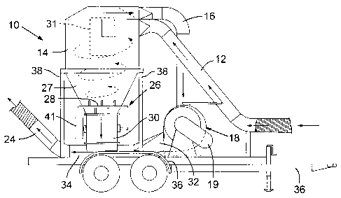
Fig. 1 is a perspective front view of an exemplary embodiment of a lost
circulation material delivery system.
Fig. 2 is an elevational left side view of the delivery system of Fig. 1.
Fig. 3 is a top plan view of the delivery system of Fig. 2.
Fig. 4 is a perspective view of another embodiment of a lost circulation
material delivery system using circulation material containing bulk bags.
Fig. 5 is an elevational side view of the delivery system of Fig. 4.
Fig. 6 is an elevational side view of another embodiment of a lost circulation
material delivery system using an auger mechanism.
DETAILED DESCRIPTION
Embodiments of a lost circulation material delivery system for delivering
lost circulation material, preferably cottonseed hulls, from a source to a
drilling well
site are described herein. The drilling well site can include an oil or gas
drilling well
bore in communication with a mud system, such as a mud pit, configured to
prepare
and convey drilling fluid or drilling mud into the drilling well bore. The
lost
circulation material delivery system delivers lost circulation material and
introduces
it to the mud system to be mixed with the drilling fluid prior to the fluid
entering the
pit. The various embodiments of the delivery system are configured such that
the
lost circulation material need not be drawn into and passed through a pump,
fan or
- 5 -
CA 02562819 2006-10-06
other material moving device with moving parts along its path to be delivered
to the
mud system.
According to one exemplary embodiment, a lost circulation material delivery
system is indicated generally at 10 in Figs. 1-3.
Referring to Fig. 1, the delivery system 10 includes a lost circulation
material
retrieval passageway, such as hose or pipe 12, with an inlet end positioned in
contact
with or near a source, such as, e.g., a van trailer (not shown) with a supply
of lost
circulation material, and an opposite outlet end coupled generally tangential
to an
upper portion of a cylindrical hollow cyclone housing 14. The housing 14 can
be
mounted to and at least partially supported by a box frame 38 made of multiple
reinforcing tubular members. In some implementations, the hose 12 can include
a
rigid fixed pipe section and a flexible tube section coupled to the pipe
section. An
air drawing hose or pipe 16 is coupled to an uppermost portion of the cyclone
housing 14, such that it is in air receiving communication with the central
channel
31 at one end, and a material moving device, e.g., a fan portion 20 of a pump
mechanism 18, at an opposite end.
The fan can be driven by a driving device, such as a 20-horsepower electrical
motor 22, that is coupled to the fan via a belt housed in belt cover 19 and
engaged
with a shaft of the driving device and the fan. Although a 20-horsepower
electrical
motor is shown, it is recognized that other motors having varying power
outputs can
be used.
As shown in Figs. 2 and 3, the system 10 also includes a sorting portion 26
coupled to a bottom end of the cyclone housing 14 and in hull receiving
communication with the housing. The sorting portion 26 includes a funnel, or
hopper, portion 27 attached to the cyclone housing 14 at an upper end and a
vacuum
dropper 30 at a lower end. The funnel portion 27 can have a frustoconical
shape or
any shape where the upper end of the funnel portion has a larger cross-section
than
the lower end of the funnel portion.
A separator 28 is positioned within the funnel portion 27 intermediate the
upper and lower ends. In some implementations, the separator 28 includes a
stationary horizontally oriented grate-like plate having multiple openings
with
- 6 -
CA 02562819 2006-10-06
projecting spaced-apart partitions or fins positioned adjacent the openings.
In other
implementations, the separator 28 can be movable.
The vacuum dropper 30 is coupled to a generally elongate rectangular blow
box 34 at a lower end and has an opening at its lower end that opens into a
material
receiving opening in the blow box. The vacuum dropper 30 includes a horizontal
rotatable shaft within a housing that is selectively rotated by an electric
motor
mechanism 41, such as a motor and gear assembly, coupled to the shaft. The
shaft
has a series of paddles or fins extending the length of the shaft. The fins
can be
spaced apart at approximately equal distances from each other.
The blow box 34 is positioned downstream of the pump mechanism 18 and
is separated from the pump mechanism by an enclosed passageway or conduit 32.
The blow box 34 has an inlet end coupled to the enclosed passageway or conduit
32
and an outlet end coupled to a lost circulation material delivery passageway,
such as
hose or pipe 24. The hose 24 extends from the blow box 34 to a drilling well
mud
system, or mud pit, (not shown) that can be located proximate the drilling
well. In
some implementations, the hose 24 can include a rigid pipe section coupled to
a
flexible tube section.
In some implementations, the system 10 can be removably mounted to a
transportation vehicle, such as trailer 36 to be transported to an oil or gas
drilling
well site. In some exemplary implementations, the system can be between
approximately 8 and 12 feet high and the pipes or hoses 12, 16, 24 can have an
approximate internal diameter between about 8 and 14 inches. In a specific
implementation, the system 10 is approximately ten feet high and the pipes or
hoses
12, 16, 24 have an approximate internal diameter of about 10 inches.
In operation, the electrical motor 22 is selectively operated to drive, or
rotate,
a fan housed within the fan portion 20. When rotated, the blades of the fan
are
oriented to remove air located approximately within the generally cylindrical
volume with a cross-section indicated by dashed-line 31 in Fig. 2 from the
cyclone
housing 14 through pipe 16 to create a vacuum, i.e., negative pressure, which
acts to
draw in air from the lost circulation material source via hose 12. The air
drawn
through the hose 12 urges lost circulation material, such as cottonseed hulls,
to be
drawn through the hose 12 with the air. The cottonseed hull and air mixture
flows
- 7 -
CA 02562819 2006-10-06
through the hose as indicated in Figs. 2 and 3 until it enters the cyclone
housing
where the cottonseed hulls are separated from the air as they flow cyclically
and
downwardly as indicated into the funnel portion 27 until they contact the
separator
28.
Because of the cyclonic effect of the lost circulation material upon entering
the housing 14, the air within the volume 31, which is approximately coaxial
with
the housing, is substantially void of lost circulation material. Accordingly,
the pump
mechanism 18, receives the air from the housing 14 via pipe 16 does not
receive or
interact with lost circulation materials.
The separator 28 receives the cottonseed hulls, the separator fins separate,
or
break up, hulls that may be clumped together in masses, and the hulls fall
through
the multiple openings into the vacuum dropper 30. Hulls falling through the
separator 28 collect in the spaces defined between adjacent fins as the vacuum
dropper shaft rotates. Additional rotation causes the hulls collected in each
space to
fall into the blow box 34 as the shaft rotates to expose the respective spaces
to the
material receiving opening in the blow box. The rate of rotation of the shaft
can be
selectively and variably controlled by operation of the motor mechanism 41 to
meter
the flow or amount of cottonseed hulls allowed to pass into the blow box 34.
In
some implementations, the dropper 30 has between 6 and 8 fins and the shaft
can be
controlled to rotate between about 5 and 60 rpm. In certain implementations,
the
fins are made of a resilient rubber or elastomeric material.
Air drawn from the cyclone housing 14 passes through the pump 18 and is
expelled or blown into the blow box 34 via hose 32. The air flowing through
the
blow box 34 carries the hulls entering the blow box from the dropper 30 into
the
hose 24 at a relatively constant rate. The hulls are then transported through
the hose
24 to the drilling well mud system to be introduced into the drilling fluid.
Referring now to Figs. 4 and 5, another embodiment of a lost circulation
material delivery system is indicated generally at 50 and includes a pump 52
with a
fan that is selectively driven by a driving device, such as a 10-horsepower
electrical
motor 53, to deliver lost circulation material, such as cottonseed hulls, from
a source
other than a van trailer or truck, such as bulk bag 58, to a drilling well mud
system
- 8 -
CA 02562819 2006-10-06
or mud pit (not shown). Although a 10-horsepower electrical motor is shown, it
is
recognized that other motors having varying power outputs can be used.
The bulk bag 58 contains cotton seed hulls and can be suspended from a
rigid box frame 56 directly over a sorting portion 62 by a suspension element,
such
as suspension straps 60, which can be made from an interwoven fabric mesh, a
chain, a spring, or other suitable coupling element or elements. In some
implementations, the bulk bag 58 can contain between approximately 1,500 and
2,000 or more pounds of lost circulation material with multiple bulk bags
being
transportable to and storable at the drilling site.
The sorting portion 62 can include a surge hopper 64 at an upper first end
and a blow box 70 at a lower end. A vacuum dropper 68, with features similar
to
vacuum dropper 30 of Figs. 2-3, is positioned intermediate the surge hopper 64
and
the blow box 70 and a separator 66, similar to separator 28 of Figs. 2-3, can
be
positioned within the hopper.
The pump 52 includes an inlet coupled to an air intake passageway 54 and an
outlet coupled to a connecting passageway 72, which couples the pump outlet
with
an inlet end of the blow box 70. A lost circulation material delivery
passageway,
such as hose 74, can be connected to an outlet end of the blow box 70 at a
first end
with a second end opposite the first end positioned in ejecting communication
with a
drilling well mud pit.
The system 50 can be mounted to a transportable platform 76, which can be
easily transported by a trailer or truck to the drilling well site. In
specific
implementations, the system 50 can be between approximately 10 and 13 feet
high,
the frame 56 can be between approximately 4 and 6 feet wide and the pipe 74
can
have between an 8- and 10-inch internal diameter. Also, a distance between the
horizontal shafts of the separator 66 and the vacuum dropper 68 can be between
approximately 1 and 3 feet.
In operation, a forklift, or other lifting device, lifts a bulk bag 58
containing
cottonseed hulls and the suspension elements, each with one end initially
secured to
either the frame 56 or an upper portion of the bag 58 and the other end
coupled to
the bag or frame, respectively, suspend the bag from the frame. A sealed pre-
formed
opening in a lower portion of the bulk bag 58 is unsealed, for example, by
untying a
- 9 -
CA 02562819 2006-10-06
knotted rope, and gravity urges the cottonseed hulls to fall into the surge
hopper 64.
The separator breaks up hull masses that may have formed and the flow of hulls
into
the blow box are metered by the vacuum dropper 68.
The electric motor is activated to drive the fan, which draws in ambient air
via the air intake tube 54. The air is then expelled or blown out of the pump
52 and
into the hose 72 before passing into and through the blow box 70. The air
flowing
through the blow box 70 carries the hulls entering the blow box from the
dropper 68
into the hose 74. The hulls are then transported through the hose 64 to the
drilling
well site at a relatively constant rate to be introduced into the mud pit.
Referring now to Fig. 6, another embodiment of a lost circulation material
delivery system is indicated generally at 100 and includes an auger-type
conveyor
portion 102. Similar to the delivery system 50 of Figs. 4 and 5, the delivery
system
100 includes a bulk bag 104 containing cottonseed hulls attached to a rigid
box
frame 106 and suspended over a sorting portion 108. The sorting portion 108
includes a surge hopper 110, separator 112 and a vacuum dropper 68 configured
to
receive hulls from the bulk bag 104 and introduce them into the auger-type
conveyor
portion 102 in a manner similar to that described above for introducing hulls
into the
blow boxes 34, 70 of Figs. 1-5.
The conveyor portion 102 includes a channel, such as pipe 122, housing a
rotating auger 124 and being pivotable about an inlet end 130. A drive motor
126 is
coupled to the auger 124 proximate the inlet end 130 of the pipe 122 to
rotatably
drive the auger. The pipe 122 is attached to an actuator, such as hydraulic
actuator
166, which is selectively driven by a hydraulic power unit 118 to raise or
lower an
outlet end 132 of pipe 122 opposite the inlet end 130.
In a specific implementation, the pipe 122 can have an approximate internal
diameter of approximately 10 inches and the frame 106 can be approximately 12
feet
high and 5.5 feet wide. The position of the actuator 116 and the length of the
pipe
122 can be predetermined to produce a desired vertical and horizontal position
of the
conveyor portion pipe outlet end 132. For example, the outlet end 132 can be
positioned at approximately 14 feet above the ground.
In operation, the cottonseed hulls from the bulk bag 104 pass through the
sorting portion 108 in a manner similar to that described above as relating to
the
-10-
CA 02562819 2013-07-16
63198-1524
sorting portion 62 shown Figs. 4-5, except that instead of being introduced
into a
blow box, the hulls are introduced into the conveyor portion 102. The drive
motor
126 rotates the auger 124 such that the auger blades continually shill or
convey the
hulls upward along the pipe 122 at a relatively constant rate until the hulls
are
expunged through an opening 134 in the pipe proximate its outlet end 132 and
fall,
or are otherwise introduced, into a drilling well mud system or pit (not
shown).
The system 100 can be mounted to a transportable platform 120 that can be
moved to a location proximate the drilling well or mud pit. The actuator 116
can be
selectively extended and retracted to raise and lower, respectively, and move
rearwardly and forwardly, respectively, the outlet end of the pipe 122 such
that the
hulls exiting the opening in the outlet end fall into the drilling well mud
system.
In several implementations, many of the rigid components of the illustrated
embodiments, such as the cyclone housing, frames, rigid sections ofthe pipes
and
sorting portion components, can be made from steel, while the flexible
components,
such as the flexible sections of the pipes, can be made from an elastomeric or
plastic
material.
Although one preferred lost circulation material is cottonseed hulls, other
lost
=
circulation materials, such as cedar fiber, paper, cottonseed burrs, sawdust,
cellophane, calcium carbonate, phenolic plastic or other material that can be
used as
an additive in the drilling fluid to fill fissures, porous or fractured
formations, or
other undesirable subterranean characteristics existing or formed in the side
walls of
the well-bore, can also be used in the described systems and methods.
In view of the many possible embodiments to which the principles of the
disclosed invention may be applied, it should be recognized that the
illustrated
embodiments are only preferred examples of the invention and should not be
taken
as limiting the scope of the invention. Rather, the scope of the invention is
defined
by the following claims. We therefore claim as our invention all that comes
within
the scope of these claims.
-11-