Note: Descriptions are shown in the official language in which they were submitted.
CA 02563002 2006-10-02
WO 2005/100539 PCT/US2005/011602
DISPOSABLE CHAMBER FOR ANALYZING BIOLOGIC FLUIDS
BACKGROUND OF THE INVENTION
1. Technical Field
[0001] The present invention relates to chambers for analyzing biologic fluids
in
general, and to chambers that permit the enumeration of particulate matter
within the
biologic fluid in particular.
2. Background Information
[0002] The classic method of enumerating particles in a liquid medium, such as
blood cells in whole blood or bacteria or other material in urine or other
biologic fluid is
the hemocytometer, which includes a chamber manufactured to a precise height
and
having visible ruled areas of precise dimension. The liquid containing the
particles to be
enumerated is introduced into the chamber. The liquid is diluted if necessary
to reduce
the number of particles to a manageable number. The operator then counts the
number of
particles in a given demarcated area. Since the area and height of the chamber
are
precisely known, the particle count per volume can be calculated. Although
these
chambers are generally ruled to demarcate a known area, this is not necessary
if such a
chamber is used in an image analyzer. With an image analyzer, rulings on the
chamber
itself are unnecessary because the field of view can be exactly calculated
from the image.
[0003] Because they are precisely manufactured, hemocytometer chambers are
relatively expensive and were not considered disposable. Modern precision
plastics
molding techniques have allowed the manufacture of some types of hemocytometer
chambers at sufficiently low cost so as to be considered disposable in some
instances, but
chambers requiring substantial precision and/or thicknesses less than the
traditional 0.1
mm are very difficult to mold accurately.
1
CA 02563002 2006-10-02
WO 2005/100539 PCT/US2005/011602
[0004] U.S. Patent No. 4,950,455 describes a counting chamber formed from a
rigid glass slide and a rigid glass coverslip with rigid particles, such as
glass beads,
contained therebetween. The beads maintain a thin spacing between the slide
and
coverslip, thereby fonning the counting chamber.
[0005] A counting chamber formed from rigid upper and lower panels separated
by rigid particles has substantial limitations, however. Referring to FIGS. I
and 2, a prior
art assembly generally denoted by 2 consists of a lower glass slide 3, an
upper glass
coverslip 4 and an entrapped layer formed from a plurality of glass beads 5.
Because any
microscopic beads are not completely uniform, having a coefficient of
variation of the
diameter of up to 10% or greater, the larger beads 6 "prop-up" the coverslip 4
to some
extent, and the smaller beads 7 have no effect on the separation. The
differences in bead
diameter is a problem because while it is easy to determine and/or control the
mean
diameter of the beads, the spread of diameters is less well controlled,
rendering the
system less accurate than is desired. This results in a separation between the
upper and
lower layers of about the mean bead diameter plus one standard deviation. A
greater
problem is the presence of particulate debris as shown in FIG. 2. This debris
can be
present when the chamber is made or can be introduced by the environment or
from a
sample. The debris 8 can "prop up" the coverslip 4 and create a large area of
increased
volume in the chamber, which destroys its accuracy.
[0006] Another issue with this type of prior art chamber is that it is
difficult to
package a plurality of such disposables in an instruinent used for
automatically scanning
and counting particles, such as an image analyzing system.
[0007] What is needed is an apparatus and method to overcome the limitations
of
the prior art, that provides a chamber for analyzing biologic fluids,
including the
enumeration of particulates within the fluid, which is inexpensive to produce,
relatively
insensitive to trapped particulate debris, and amenable to packaging for use
in an
automated test system.
2
CA 02563002 2006-10-02
WO 2005/100539 PCT/US2005/011602
SUMMARY OF THE INVENTION
[0008] According to the present invention, an apparatus for analyzing biologic
fluid is provided that includes a first planar member, a second planar member,
and at least
three separators. At least one of planar members is transparent. The
separators are
disposed between the members, and separate the members to form a chamber
having a
height. At least one of the members or separators is sufficiently flexible to
permit the
chamber height to approximate the mean size of the separators. During use, the
biologic
fluid to be analyzed is disposed within the chamber.
[0009] According to one aspect of the present invention, each planar member is
a
tape that can be wound on a reel. In some embodiments, the planar members are
initially
attached to one another. In other embodiments, each planar member is initially
separated
from the other planar member.
[0010] According to one aspect of the present invention, a cassette is
provided
having at least one source reel and at least one take-up reel. The planar
members are
initially wound on a source reel, and are transferred to a take-up reel during
operation of
the apparatus. An analysis region is disposed between the source and take-up
reels. The
planar members pass through the analysis region during the operation of the
apparatus.
[0011] There are numerous advantages associated the present invention. We
discovered that if a counting chamber is produced using separators disposed
between
planar members, and if at least one the planar members and separators is
flexible, the
chamber behaves differently than the prior art devices, and the difference is
highly
advantageous. When a counting chamber is filled with a liquid, the capillary
forces tend
to pull the top and bottom planar members together, thus exerting a slight
pressure on the
retained separators. This pressure will cause the flexible element to deform
in such a
manner as to cause the chamber thickness to approximate, on average, the mean
dimension of the separators disposed between the planar members. For example,
if both
top and bottom planar members are rigid and the separators are flexible,
separators larger
than the mean diameter will be compressed, and the planar members will
approximate
until more and more separators come into contact with the planar members,
preventing
3
CA 02563002 2007-01-22
further approximation. At that point, the height of the chamber approximates
the
average height of the separators and is readily ascertainable, provided the
standard
deviation of the separator heights is acceptable and the separators are
sufficiently
flexible. In another example, if the separators are rigid and the top planar
member is
flexible, the top planar member will deform and be "tented-up" in a small area
around
each of the larger separators and be lower over smaller separators. The
chamber will
have an average height which closely approximates average separator height,
provided the top planar member is sufficiently flexible.
[0012] An advantage of the present invention is, therefore, that a chamber
is formed having a volume that is accurately determinable because the height
of
the chamber is substantially uniform.
[0013] Another advantage of the present invention is that it can be
manufactured in an inexpensive form and still provide the desired accuracy.
The
present invention does not require accurately machined voids or separators to
accurately establish volume. Consequently, the invention can be manufactured
inexpensively and still provide the desired accuracy. In addition, because it
can be
manufactured inexpensively, the present invention can practically be offered
in a
disposable form.
In another aspect, the present invention provides an apparatus for
analyzing biologic fluid, comprising: a first planar member; a second planar
member,
wherein at least one of the first planar member and second planar member is
transparent;
and at least three separators disposed between the planar members, each
separator
individually having a height and the separators collectively having a mean
height,
separating the planar members to form a chamber having a height extending
between the
planar members; wherein at least one of the first planar member, second planar
member,
or separators is sufficiently deformable to permit the chamber height to be
substantially
equal to the mean height of the separators.
In another aspect, the present invention provides an apparatus for
analyzing biologic fluid, comprising: a tape including a first planar member
and a second
planar member spaced apart from one another and bonded together at discrete
points,
4
CA 02563002 2007-01-22
wherein at least one of the first planar member and second planar member is
transparent,
and at least one chamber having a height is formed between the planar members,
and at
least three separators are disposed in each of the at least one chamber, each
separator
individually having a height and the separators collectively having a mean
height, and
wherein at least one of the first planar member, second planar member, or
separators is
sufficiently deformable to permit the chamber height to be substantially equal
to the
mean height of the separators; a source reel on which the tape may be wound;
and a take-
up reel on which the tape may be wound.
In another aspect, the present invention provides an for analyzing
biologic fluid, comprising: a first planar member; a first source reel; a
second planar
member, wherein at least one of the first planar member and second planar
member is
transparent, a second source reel; a plurality of separators attached to one
of the first
planar member or second planar, each separator individually having a height
and the
separators collectively having a mean height; a pair of nip-rollers, spaced
apart from one
another an amount that causes the first planar member and second planar member
to be in
contact with substantially all of the separators when the planar members are
drawn
between the nip-rollers; at least one chamber having a height, which chamber
is formed
between the planar members downstream of the nip-rollers, and wherein at least
one of
the first planar member, second planar member, or separators is sufficiently
deformable
to permit the chamber height to be substantially equal to the mean height of
the
separators; and at least one take-up reel for receiving one or both of the
planar members.
In another aspect, the present invention provides a method of
enumerating the cellular or particulate constituents of a sample of whole,
anticoagulated
blood, comprising the steps of. providing an apparatus for analyzing biologic
fluid that
includes a first planar member, a second planar member, wherein at least one
of the first
planar member and second planar member is transparent, and at least three
separators
disposed between the planar members, each separator individually having a
height and
the separators collectively having a mean height, separating the planar
members to form a
chamber having a height extending between the planar members, wherein at least
one of
the first planar member, second planar member, or separators is sufficiently
deformable
to permit the chamber height to be substantially equal to the mean height of
the
4a
CA 02563002 2007-01-22
separators; depositing a quantity of biologic fluid into contact with one of
the first planar
member or second planar member surface; approximating the planar members to
form a
film of biologic fluid confined between the two planar members as separated by
the
separators; determining the volume of biologic fluid contained within the
film; directly or
indirectly enumerating all constituents of interest within substantially the
all of the film;
and expressing the enumerated constituents as a count per unit volume.
In another aspect, the present invention provides a method of
enumerating the cellular or particulate constituents of a sample of whole,
anticoagulated
blood, comprising the steps of. providing a tape including a first planar
member and a
second planar member spaced apart from one another and bonded together at
discrete
points, wherein at least one of the first planar member and second planar
member is
transparent, and at least one chamber having a height is formed between the
planar
members, and at least three separators are disposed in each chamber, each
separator
individually having a height and the separators collectively having a mean
height, and
wherein at least one of the first planar member, second planar member, or
separators is
sufficiently deformable to permit the chamber height to be substantially equal
to the
mean height of the separators, a source reel on which the tape may be wound,
and a take-
up reel on which the tape may be wound; depositing a quantity of biologic
fluid into the
at least one chamber; determining the volume of biologic fluid contained
within at least a
portion of the at least one chamber; directly or indirectly enumerating all
constituents of
interest within substantially the volume of biologic fluid; and expressing the
enumerated
constituents as a count per unit volume.
In another aspect, the present invention provides an apparatus for
analyzing biologic fluid, comprising: a first planar member; a second planar
member,
wherein at least one of the first planar member and second planar member is
transparent;
and at least three separators disposed between the planar members, each
separator
individually having a height and the separators collectively having a mean
height,
separating the planar members to form a chamber having a height extending
between the
planar members; wherein at least one of the first planar member or second
planar member
is sufficiently deformable to permit the chamber height to be substantially
unaffected by
4b
CA 02563002 2009-11-12
the presence of debris within the chamber having a height greater than the
mean separator
height.
In another aspect, the present invention provides an apparatus for analyzing
biologic fluid, comprising: a first planar member; a second planar member,
wherein at
least one of the first planar member and second planar member is transparent;
and at least
three separators disposed between the planar members, each separator having a
height
and the separators collectively having a mean height, separating the planar
members to
form a chamber having a height extending between the planar members; wherein
at least
one of the first planar member, second planar member, or separators is
sufficiently
deformable to permit the chamber height to be substantially equal to the mean
height of
the separators.
In another aspect, the present invention provides an apparatus for analyzing
biologic fluid, comprising: a tape including a first planar member and a
second planar
member spaced apart from one another and bonded together at discrete points,
wherein at
least one of the first planar member and second planar member is transparent,
and at least
one chamber having a height is formed between the planar members, and at least
three
separators are disposed in each chamber, each separator individually having a
height and
the separators collectively having a mean height, and wherein at least one of
the first
planar member, second planar member, or separators is sufficiently deformable
to permit
the chamber height to be substantially equal to the mean height of the
separators; a source
reel on which the tape may be wound; and a take-up reel on which the tape may
be
wound.
In another aspect, the present invention provides an apparatus for analyzing
biologic fluid, comprising: a first planar member; a first source reel; a
second planar
member, wherein at least one of the first planar member and second planar
member is
transparent, a second source reel; a plurality of separators attached to one
of the first
planar member or second planar, each separator individually having a height
and the
separators collectively having a mean height,; a pair of nip-rollers, spaced
apart from one
4c
CA 02563002 2009-11-12
another an amount that causes the first planar member and second planar member
to be in
contact with substantially all of the separators when the planar members are
drawn
between the nip-rollers; at least one chamber having a height, which chamber
is formed
between the planar members downstream of the nip-rollers, and wherein at least
one of
the first planar member, second planar member, or separators is sufficiently
deformable
to permit the chamber height to be substantially equal to the mean height of
the
separators; and at least one take-up reel for receiving one or both of the
planar members.
In another aspect, the present invention provides a method of enumerating
cellular or particulate constituents of a sample of whole, anticoagulated
blood as a
function of volume, comprising the steps of. providing an apparatus for
analyzing
biologic fluid that includes a first planar member, a second planar member,
wherein at
least one of the first planar member and second planar member is transparent,
and at least
three separators disposed between the planar members, each separator
individually
having a height and the separators collectively having a mean height,
separating the
planar members to form a chamber having a height extending between the planar
members, wherein at least one of the first planar member, second planar
member, or
separators is sufficiently deformable to permit the chamber height to be
substantially
equal to the mean height of the separators; depositing a quantity of biologic
fluid into
contact with one of the first planar member or second planar member surface;
wherein
the biologic fluid forms a film confined between the two planar members as
separated by
the separators; determining the volume of biologic fluid contained within the
film;
enumerating all constituents of interest within substantially all of the film;
and expressing
the enumerated constituents as a count per unit volume.
In another aspect, the present invention provides a method of enumerating
cellular or particulate constituents of a sample of whole, anticoagulated
blood as a
function of volume, comprising the steps of: providing a tape including a
first planar
member and a second planar member spaced apart from one another and bonded
together
at discrete points, wherein at least one of the first planar member and second
planar
member is transparent, and at least one chamber having a height is formed
between the
4d
CA 02563002 2009-11-12
planar members, and at least three separators are disposed in each chamber,
each
separator individually having a height and the separators collectively having
a mean
height, and wherein at least one of the first planar member, second planar
member, or
separators is sufficiently deformable to permit the chamber height to be
substantially
equal to the mean height of the separators, a source reel on which the tape
may be wound,
and a take-up reel on which the tape may be wound; depositing a quantity of
biologic
fluid into the at least one chamber; determining the volume of biologic fluid
contained
within at least a portion of the at least one chamber; enumerating all
constituents of
interest within substantially all of the volume of biologic fluid; and
expressing the
enumerated constituents as a count per unit volume.
In another aspect, the present invention provides an apparatus for analyzing
biologic fluid, comprising: a first planar member; a second planar member,
wherein at
least one of the first planar member and second planar member is transparent;
and at least
three separators disposed between the planar members, each separator
individually
having a height and the separators collectively having a mean height,
separating the
planar members to form a chamber having a height extending between the planar
members; wherein at least one of the first planar member or second planar
member is
sufficiently deformable to permit the chamber height to be substantially
unaffected by the
presence of debris within the chamber, which debris has a height greater than
the mean
separator height.
[0014] These and other objects, features and advantages of the present
invention
will become apparent in light of the detailed description of the invention
provided below,
and as illustrated in the accompanying drawings.
BRIEF DESCRIPTION OF THE DRAWINGS
[0015] The principles of the invention are further clarified by referring to
the following figures, where:
FIG. 1 is a cross-sectional schematic of the invention of the prior art,
using a system in which all elements are rigid;
4e
CA 02563002 2009-11-12
FIG. 2 is a cross-sectional schematic of the invention of the prior art,
using a system in which all elements are rigid, and where particulate debris
has been
trapped;
FIG. 3 is a cross-sectional schematic of the present invention, where the
4f
CA 02563002 2006-10-02
WO 2005/100539 PCT/US2005/011602
separators are flexible relative to the top and bottom planar members;
FIG. 4 is a cross-sectional schematic of the present invention, where the
top planar member is flexible in relation to all other elements;
FIG. 5 is a cross-sectional schematic of the present invention, where the
top planar member is flexible in relation to all other elements and where
particulate debris
has been trapped;
FIG. 6 is a schematic view of a first embodiment of the present invention;
FIG. 6A is a schematic view of as instrument designed to utilize a second
embodiment of the present invention;
FIG. 7 is a schematic view of a cassette containing the first embodiment of
the present invention;
FIG. 8 is a schematic view of an instrument designed to utilize an
embodiment of the present invention;
FIG. 9 is a schematic view of the instrument of FIG. 6 where the sample
has been added to the planar member;
FIG. 10 is a schematic view of the sample after spreading out between the
planar members; and
FIG. 11 is a schematic view of the analysis field.
DETAILED DESCRIPTION OF THE INVENTION
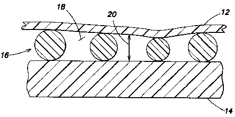
[0016] Referring to FIGS. 3-11, the present invention apparatus 10 for
analyzing
biologic fluid includes a first planar member 12, a second planar member 14,
and at least
three separators 16. At least one of planar members 12, 14 is transparent. The
separators
16 are disposed between the members 12, 14, and separate the planar members
12, 14 to
form a chamber 18 having a height 20. At least one of the members 12, 14 or
separators
16 is sufficiently flexible to permit the chamber height 20 between the
members 12, 14 to
approximate the mean height of the separators 16.
[0017] The separators 16 can be any structure that is disposable between the
planar members 12, 14, operable to space the planar members 12, 14 apart from
one
CA 02563002 2006-10-02
WO 2005/100539 PCT/US2005/011602
another. The dimension of a separator 16 that extends between the planar
members is
referred to herein as the height 22 of the separator 16_ The heights 22 of the
separators 16
typically do not equal one another exactly, but are within commercially
acceptable
tolerance for spacing means used in similar analysis apparatus. Spherical
beads are an
example of an acceptable separator 16 and are commercially available from, for
example,
Bangs Laboratories of Fishers, Indiana, USA.
[0018] In some embodiments, the separators 16 consist of a material that has
greater flexibility than one or both of the first planar member 12 and the
second planar
member 14; i.e., relatively speaking, one or both of the planar members 12, 14
may be
considered to be rigid relative to the separators 16 and the separators 16 may
be
considered to be flexible relative to one or both of the planar members 12,
14.
[0019] In other embodiments, the separators 16 consist of a material that has
less
flexibility than one or both of the first planar member 12 and the second
planar member
14; i.e., relatively speaking, one or both of the planar members 12, 14 may be
considered
to be flexible relative to the separators 16 and the separators 16 may be
considered to be
rigid relative to one or both of the planar members 12,, 14.
[0020] Subject to the flexibility characteristics described above, the planar
members 12, 14 can be made from a variety of materials, provided at least one
of the
planar members 12, 14 is transparent. Transparent plastic films consisting of
acrylic or
polystyrene are examples of acceptable planar members 12, 14. Planar members
12, 14
in the form of a tape are particularly useful because they can be easily wound
on a reel.
In some embodiments, one or both of the first planar member and second planar
member
includes a plurality of rigid elements linked to one another.
[0021] Now referring to FIG. 3, in an embodiment of the present invention 10
the
first planar member 12 and the second planar member 14 are separated by a
chamber 18
formed by plurality of separators 16 in the form of spherical beads. These
beads 16 are
formed from a material that has greater flexibility than the first planar
member 12 and the
second planar member 14; i.e., the planar members 12, 14 may be considered to
be rigid
relative to the beads 16 and the beads 16 maybe considered to be flexible
relative to the
6
CA 02563002 2007-01-22
planar members 12, 14. Plastic beads 16 formed from polystyrene,
polycarbonate,
silicone and the like can be used. In this example, larger beads 16A are
compressed
to the point where the planar members 12, 14 have approximated to the point
where
most beads 16 are touching the interior surfaces 24 of the planar members 12,
14,
thereby making the chamber height 20 just slightly less than the mean bead
diameter.
[0022] In FIG. 4, in another embodiment of the present invention 10 the first
planar member 12 is formed from a material more flexible than the spherical
beads
16 and the second planar member 14, and will overlay the beads 16 in a tent-
like
fashion, where the areas between the beads 16 are some arbitrary height
determined
by the bead diameters supporting that piece of the planar member 12. Any
transparent
plastic film, such as acrylic, polystyrene, or the like will work provided it
is thin
enough to flex as shown. It should be apparent that in this circumstance,
although
small local areas will deviate from the desired chamber height 20, the average
height
of all the tented areas will be very close to that of the mean bead diameter.
Our
testing indicates that that the mean chamber height can be controlled to 1% or
better
at chamber heights of less than four microns using the present invention.
[0023] FIG. 5 shows the chamber 18 of FIG. 4 wherein a piece of particulate
debris 26 has lodged. The first planar member 12 over the debris 26 has tented
up,
and the area under the debris 26 is of unknown height, but this disturbance
only
affects a small area of the chamber 18, as opposed to what would occur if the
whole
system was rigid.
[0024] FIG. 6 shows another embodiment of the invention 10, where the
second planar member 14 is formed from a one inch wide strip of transparent
plastic film (e.g., polyethylene terphthalate (PET)) of approximately fifty
(50)
microns in thickness, the first planar member 12 is formed from the same
material
as the second planar member 14 but in twenty-three (23) micron thickness, and
the
chamber 18 therebetween is formed from a plurality of plastic beads 16 with a
mean diameter of four (4) microns. The first planar member 12 has an inner
coating of a coloration agent, such as acridine orange, which will
differentially
color living white blood cells when examined with fluorescent illumination.
7
CA 02563002 2007-01-22
Other reagents for fluorescence include astrozone orange, FITC, rhodamine and
the
like. Reagents which may be used with transmitted light to differentially
color the white
blood cells include astrozone orange, methylene blue, oxazine170. The first
planar
member 12 includes a plurality of ports 28 (e.g., approximately three hundred
(300)
microns in diameter) punched at regular intervals, and the planar members 12,
14 are
bonded at some points 29 between the ports 28 to form a series of separated
analysis
chambers 18.
[0025] This spacing between the two planar members 12, 14 in this
embodiment is accomplished by spherical beads 16 of known and precisely
controlled
diameter (e.g., about four (4) microns in diameter). These beads 16 are
randomly
distributed on at least one of the planar members 12, 14 and can be attached
as part of
the reagent film containing the staining material. The material retaining the
beads 16
should be such that they remain affixed to the planar member 12, 14 until at
least after
the fluid film movement has ceased so that they will not be swept away. An
acceptable
method of coating a film with beads 16 is to suspend the beads 16 in
approximately a
0.5% solution of phytagel and apply a thin coating of the suspension by either
spraying
or meniscus coating. The optimum concentration of beads 16 will depend upon
the type
of bead and their method of manufacture, as well as the relative rigidity of
the top and
bottom planar members 12, 14. This concentration can be determined empirically
on a
batch-to-batch basis by applying a series of bead concentrations to the planar
members
12, 14 to be used and then adding a liquid containing a dye, such as
hemoglobin, which
will give a useful optical density at the liquid layer thickness used. The
average optical
density of the liquid layer is then plotted against bead 16 density to
determine the point
where additional bead concentration produces no useful change in liquid layer
thickness; i.e., the point where the chamber height 20 is substantially
uniform. An
alternate means of providing the separators is to negatively emboss one of the
planar
members 12, 14 with projections having approximately the same height of about
four
(4) microns, for example by laser-etching pits in a nip-roller and passing one
planar
member 12, 14 through the nip-roller assembly.
[0026] FIG. 7 shows a cassette 30 having a shell 32 in which a source reel 34,
a
8
CA 02563002 2010-10-06
take-up reel 36, and a tape 38 extending therebetween are disposed. The "tape
38" is the
embodiment of the present invention shown in FIG. 6 and described above.
Initially, the
tape 38 is wound on the source reel 34. Advancement of the tape 38 is
controlled by
rollers 40, which apply traction to the tape 38 at a point remote from the
examination area
42 and can act to draw the tape 38 from the source reel 34 as required. The
cassette 30
has a through-hole that allows an optical system to provide illumination
through the tape
38.
[0027] FIG. 8 shows an optical analysis system 44 containing the cassette 32.
The
optical analysis system 44, which consists of joined components including a
lens 46, a
variable-wavelength light source 48 ancf a CCD camera 50 are movable in three
dimensions so as to allow the optical system 44 to focus upon the tape 38 in
the
examination area 42 and provide X-Y movement so as to allow scanning of the
entire
examination area 42, all under control of a system computer 52. Not shown is
the
sampling probe for extracting a biologic fluid (e.g., blood) from a sample
tube and
depositing a small drop on the tape 38. Thus sampling device can take the form
of a tube-
piercing or similar probe, which uses a stepping motor-driven syringe to
extract and
deposit biologic fluid samples. These devices are widely employed and well
known to
the art, and therefore will not be described further here.
[0028] FIG. 9 shows the assembly of FIG. 8 just after a drop of biologic fluid
54
(e.g., blood) has been deposited into the sample entry port 28 (see FIG. 6) of
a chamber
18 formed between the planar members 12, 14.
[0029] FIG. 10 is a schematic view of the entire area of the sample film 64 of
biologic fluid 54, which generally has an irregular border. In this example,
the biologic
fluid is blood. Because the white blood cells within the sample film 64 tend
to become
readily entrapped in the chamber 18, they are generally found in highest
concentration
within a few millimeters of the port 28.
[0030] FIG. 11 is a schematic view of the analysis field 66 in FIG. 10, which,
in
the case of a whole blood sample, would show red blood cells 56, white blood
cells 58,
platelets 60, all surrounded by the blood plasma 62. The beads 16 are also
seen but are
9
CA 02563002 2009-11-12
readily distinguished from all other elements because of their size and
refractive index.
[0031] The characterization of the white blood cells 58 (white blood cell
differential count) is performed by the classification of each individual
white blood cell
58 as it is encountered using either traditional image-processing methods or
by the
technique described in U.S. Patent Nos. 5,321,975 and 6,350,613. A number of
supravital
stains have been described which differentially color the different classes of
white blood cells
58 as has been described in U.S. Patent No. 6,235,536. Because the white blood
cells 58 are
slightly compressed and readily imaged, stored images of cells are viewable by
the
technologist in the case of questionable cell classifications.
[0032] As an example of the utility of this invention, the white blood cell 58
count of the sample film 64 may be performed by enumerating all of the white
blood
cells 58 found within the sample film 64 and dividing that number by the
volume of the
sample film 64. Although it is possible to deposit a specific amount of sample
within
the chamber 18, it is preferable to deposit an approximate amount and
indirectly
measure the volume. This can be done by mechanisms such as: 1) the volume of
the
drop of sample when first deposited can be calculated by interferometric
imaging using
optical techniques available from sources such as the Zygo Corporation of
Middlefield,
Connecticut USA; or 2) the volume of sample following film formation is
calculated by
measuring the area of the film 64 and multiplying this by the average height
of the film.
[0033] Figure 6A shows an optical analysis system 44 containing another
embodiment of the present invention 10 that includes a cassette 30 in which a
second
planar member reel 68, first planar member reel 70, and take-up reel 72.
Advancement of
the planar members 12, 14 is controlled by take-up nip-rollers 74, which apply
traction to
the combined planar members 12, 14 at a point remote from the examination area
42 and
can act to draw the planar members 12, 14 from their reels 68, 70 as required.
The optical
analysis system 44, which consists of joined components including a lens 46, a
variable-
wavelength light source 48 and a CCD camera 50 are movable in three
CA 02563002 2007-01-22
dimensions so as to allow the optical analysis system 44 to focus upon the
joined
planar members 12, 14 in the examination area 42 and provide X-Y movement so
as to
allow scanning of the entire examination area 42, all under control of a
system
computer 52. A drop of biologic fluid 54 (e.g., blood) is shown deposited onto
the
second planar member 14. The nip-rollers 74 are operable to advance the planar
members 12, 14 to a point just past the nip-rollers 74, where the separators
16 disposed
between the planar members 12, 14 are in contact with each planar member 12,
14, and
the biologic fluid contacts the interior surface 24 of each planar member 12,
14 and
spreads to form a thin sample film 64. The planar members 12, 14 are then
advanced so
as to be readable by optical analysis system 44.
[0034] Since the overall accuracy of the system 44 when using a method of
volume calculation depends upon the accuracy of the chamber height 20, it may
be
expedient to use an internal standard means to calculate the exact chamber
height 20.
An example of an internal standard includes a flexible or flowable material
which is
not miscible with the sample and which contains a known, stable and uniform
concentration of a sensible optical dye. The material can be dyed flexible
beads, dyed
oil or the like, and may be present in one or more areas of the chamber 18.
Since the
optical density is in direct proportion to the thickness of the calibrator
material,
measurement of the optical density of the part of the calibrator material
which
completely fills the chamber height 20 will allow the calculation of the exact
chamber
height 20 to within the precision capabilities of the optical system.
[0035] Although the most frequent use for such a chamber 18 will be for
enumerating blood cells in whole blood, it is equally useful for examination
of any
undiluted fluid having sufficient particles to count. The chamber height 20 is
not
limited to the disclosed four microns but can be larger or smaller to
accommodate
different separator sizes and/or concentrations.
[0036] Although this invention has been shown and described with respect to
the detailed embodiments thereof, it will be understood by those skilled in
the art that
various changes in form and detail thereof may be made without departing from
the
spirit and the scope of the invention.
11