Note: Descriptions are shown in the official language in which they were submitted.
CA 02564079 2009-06-18
Fixation Arrangement for Bearing Bushings on a Universal Joint Yoke
Description
The invention relates to a fixation arrangement for bearing bushings on a
universal joint yoke.
From DE 102 61 114 Al different fixation arrangements for bearing bushings on
a universal joint yoke are known and comprise a universal joint yoke with a
yoke
base, which forms a longitudinal axis. From the yoke base two yoke arms
project.
They are arranged projectingly diametrically off-set from the longitudinal
axis in
the same direction from the yoke base. Each yoke arm has a through extending
bearing bore, wherein the bearing bores of both yoke arms are centred on a
common bore axis, which intersects at a right angle the longitudinal axis. The
yoke arms have, respectively, on an outer face, facing away from the
longitudinal
axis and off-set towards the yoke base, when seen in a longitudinal sectional
view, containing the bore axis, and facing the bearing bore a circular arc
groove.
The centre of the circular arc groove is arranged on the bore axis. The
bearing
bushing comprises a bushing bottom and a circumferential wall. It is
accommodated in the bearing bore of one yoke arm, wherein the bushing bottom
faces towards the outside. On its outer face, the bushing bottom has a
journal,
projecting outwardly beyond the bearing bore and provided with a
circumferentially extending groove, which centre is arranged on the bore axis.
A
securing element is provided, which is formed like a kidney-shaped bow and has
two portions, which are elastically deformable towards each other and of which
the outer portion engages in the circular arc groove and the inner portion
engages in the groove of the journal at the bushing bottom. Alternatively, a
securing element in form of a locking plate is provided, which has an outer
circumference, which is adapted to the circular arc groove and engages in the
same with an engagement portion. Furthermore, this securing element has a
through bore, through which a screw can be inserted into a central bore in the
CA 02564079 2009-06-18
2
bushing bottom. Alternatively, a plate-like securing element is proposed with
an
outer circumference, which is adapted to the circular are groove and is
provided
with a central through bore, wherein a journal, arranged to the bushing
bottom,
passes through this bore. The securing element is secured in its position by a
securing ring, which engages in a groove of the journal at the bushing bottom.
Additionally, in all embodiments at the circumferential ends of the circular
arc
groove, abutments can be provided, which secure the securing element against
rotation.
The described securing arrangements necessitate measures and processing
steps on the universal joint yoke as well as on the bearing bushing. The
journals,
attached at the outside on the bushing bottom of the bearing bushing, or the
attachment means, e.g. screws, however, enable, that to a significant degree
in
front of the end of the yoke arms, which is distanced to the yoke base, a
reduction of the rotational diameter of the universal joint yoke in the
assembled
condition of the bearing bushings is achievable, but, however, still
necessitate in
many areas a larger rotational diameter and, thus, limit also the maximum
articulation angle.
The invention is based on the object, to propose a fixation arrangement for
bearing bushings on a universal joint yoke, in which the securing element can
easily be mounted and, furthermore, further chances for the reduction of the
rotational diameter are given.
The object based on the invention is solved by a fixation arrangement for
bearing
bushings on a universal joint yoke comprising
a universal joint yoke, having
- a yoke base , forming a longitudinal axis,
- two yoke arms, which
- project diametrically off-set from the longitudinal axis in the
same direction from the yoke base,
CA 02564079 2009-06-18
3
have, respectively, a through extending bearing bore,
wherein the bearing bores of both yoke arms are arranged
on a common bore axis, which intersects at a right angle the
longitudinal axis,
- have, respectively, on an outer face, facing away from the
longitudinal axis and off-set to the yoke base, when seen in a
longitudinal sectional view, which contains the bore axis, and
facing the bearing bore a circular arc groove, which centre is
arranged on the bore axis or is off-set from the bore axis
towards the yoke base,
have, respectively, at least one securing abutment on the
outer face, which is off-set from an imaginary plane, on which
the longitudinal axis is arranged perpendicularly and which
contains the bore axis, in direction away from the yoke base,
- a separate securing element for each yoke arm, which
has an engagement portion with an outer circumference, which is
adapted to the circular arc groove and engages the same,
has for each securing abutment a securing portion,
which is supported on the securing abutment.
In this case, also the advantages are achieved, which were named in connection
with the first solution according to the invention.
For a first embodiment of this solution according to the invention it is
provided,
that the securing portion of the securing element is formed as a projection,
which
in direction away from the yoke base engages behind the mating securing
abutment, that in front of the securing abutment a support face is arranged,
which follows the path of the circular arc groove beyond the imaginary plane
up
to the securing abutment. In a further embodiment of this proposal it is
provided,
that the securing abutment is formed by a step face, facing away from the
bearing bore.
CA 02564079 2009-06-18
4
Alternatively, thereto it is provided, that the securing element has,
following the
ends of the portions of its outer circumference, adapted to the circular arc
groove, extended portions, which form support edges, extending parallel to the
longitudinal axis, and which are supported on the faces, representing the
securing abutments and which extend parallel to the longitudinal axis and
follow
the ends of the circular arc groove.
Three solutions of the object of the invention and variants for this are shown
in
the drawing and are described in more detail by means of the same.
It shows
Fig. 1 a half longitudinal sectional view of a universal joint yoke with a
first
fixation arrangement,
Fig. 2 a plan view of Fig. 1,
Fig. 3 a plan view onto a securing element for the use in connection with
the embodiment of Figures 1 and 2 as an individual component,
Fig. 4 a half longitudinal sectional view of a universal joint yoke with a
fixation arrangement according to an alternative embodiment to that
of Figures 1 to 3,
Fig. 5 a plan view of Fig. 4,
Fig. 6 the mating securing element in a plan view as an individual
component,
Fig. 7 a sectional view VII-VII of Fig. 5 for the detail X encircled in Fig.
4,
Fig. 8 a half longitudinal sectional view of a universal joint yoke with a
CA 02564079 2009-06-18
further fixation arrangement, in which a securing element is retained
by a screw in a securing recess,
Fig. 9 a plan view of Fig. 8,
5
Fig. 10 a plan view onto the securing element as an individual component,
Fig. 11 the detail X of Fig. 8 in an enlarged scale,
Fig. 12 a half longitudinal sectional view of a further variant of a fixation
arrangement with a securing recess free of an undercut,
Fig. 13 a plan view of Fig. 12,
Fig. 14 an enlarged detail, representing the securing portion of the securing
element, which is used in the embodiment of Figures 12 and 13,
before the assembly,
Fig. 15 the detail X of Fig. 13 in an enlarged scale, after the fixation of
the
securing element,
Fig. 16 a further alternative design of a securing element in a plan view,
Fig. 17 a plan view onto a universal joint yoke, in which the securing
element of Fig. 16 is used,
Fig. 17a a detail of Fig. 17 in a sectional view,
Fig. 18 a half longitudinal sectional view of a universal joint yoke with a
fixation arrangement corresponding to a solution according to the
invention, with a sickle-shaped securing element,
CA 02564079 2009-06-18
6
Fig. 19 a plan view of Fig. 18,
Fig. 19a a detail y of Fig. 19 in an enlarged scale,
Fig. 20 a sectional view XX-XX of Fig. 19 as a detail in an enlarged scale,
Fig. 21 a sectional view XXI-XXI of Fig. 19 in an enlarged scale as a detail,
Fig. 22 a plan view onto a universal joint yoke with a fixation arrangement,
which represents an alternative to that of Figures 18 to 20 in the
scope of the second solution according to the invention,
Fig. 23 the detail Y of Fig. 21 in an enlarged scale,
Fig. 24 a half longitudinal sectional view through a universal joint yoke
according to a further solution according to the invention for the
fixation of a bearing bushing, in which a support of the securing
element is achieved on the outer circumference of the bearing
bushing,
Fig. 25 a plan view of Fig. 23,
Fig. 26 the securing element with holding projections in a plan view and
Fig. 27 a detail of Fig. 26 according to the section line XXVII-XXVII in an
enlarged scale.
Following, the embodiment of Figures 1 to 3 is described, wherein in the
description it is referred to all the drawings 1 to 3 at the same time.
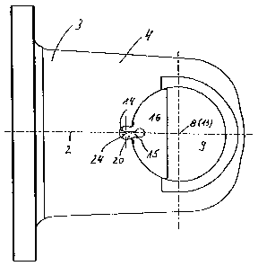
Figures 1 to 3 represent a universal joint yoke 1, wherein in Fig. 1 only one
half
CA 02564079 2009-06-18
7
of the universal joint yoke 1 is visible, the longitudinal axis 2 represents
the mirror
symmetry axis. Starting from a yoke base 3, yoke arms 4 are provided, which
are
diametrically off-set to the longitudinal axis 2 and project from the yoke
base 3 in
the same direction. The shown yoke arm 4 has an outer face, which is facing
away from the longitudinal axis 2, and an inner face 6, which is facing the
longitudinal axis 2. Between the outer face 5 and the inner face 6, a bearing
bore
7 extends, which is centred on the bore axis 8. The bore axis 8 intersects at
a
right angle the longitudinal axis 2. A yoke arm 4, not shown and diametrically
opposed to the shown bearing arm 4, has also a bearing bore 7. This is centred
on the extension of the bore axis 8.
In the bearing bore 7 a bearing bushing 9 is accommodated. This bearing
bushing 9 is, on one side, open towards the longitudinal axis 2 and, distanced
thereto, closed by a bushing bottom 10. It comprises a circumferential wall
11,
with which it rests in the bearing bore 7. This bearing bushing 9 serves to
support
a bearing journal of a journal cross to connect two universal joint yokes to
form
one universal joint. In this connection it is necessary, to secure the bearing
bushing 9 in radial direction relative to the longitudinal axis 2. For this
serves the
fixation arrangement.
On the outer face 5 of the yoke arm 4, a circular arc groove 12 is provided,
which
extends over an arc of at least 180 around the centre 13. This centre 13
coincides in the present embodiment with the bore axis 8. It is visible, that
the
circular arc groove 12 ends in front of the plane, which contains the bore
axis 8
and which plane is arranged perpendicular to the longitudinal axis 2, i.e.
when
seen from the yoke base 3.
Starting from the bearing bore 7, in the direction towards the yoke base 3
approximately centred on an radial plane relative to the longitudinal axis 2,
a
securing recess 14 extends, which starting from the bearing bore 7 has an
undercut. The securing recess 14 is formed as a circular cylindrical bore and
has
CA 02564079 2009-06-18
8
the axis 24. Correspondingly, starting from the bearing bore 7, the passage 15
towards the securing recess 14 is dimensioned smaller than the bore diameter,
forming the securing recess 14.
A securing element 16 serves for the axial retainment of the bearing bushing 9
in
the bearing bore 7, which securing element 16 is formed as a disc and is
especially visible as an individual component in Fig. 3. This disc-like
securing
element 16 has an outer circumference 18, which is formed circular arc-like
corresponding to the circular arc groove 12. The portion, directly following
the
outer circumference 18, forms an engagement portion 17, which enters the
circular arc groove 12 of the universal joint yoke 1. The securing element 16
has,
furthermore, in a plan view essentially the form of a segment of a circle with
the
outer circumference 18 and the end face 19. From the outer circumference 18, a
securing portion 20 projects, which, in the plan view shown in Fig. 3, has a
circular circumferential face 21, which is adapted to the securing recess 14.
Further, this securing portion 20 is divided by a central slot 22 into two
portions.
The slot 22 ends in the bore 23. Therefrom follows, that the two portions can
deform elastically towards each other, so that, when inserting the securing
element 16 with its engagement portion 17 along the outer face of the bushing
bottom 10 in direction towards the yoke base 3, also the securing portion 20
enters through the passage 15 the securing recess, arranged behind the
passage. The two portions of the securing portion 20, elastically deforming
towards each other during the insertion through the passage 15, can again
deform elastically away from each other and secure in this way the securing
element 16 in a double manner. The securing portion 20 in connection with the
securing recess 14 serve for the axial retainment of the securing element 16,
so
that this cannot leave with its engagement portion 17 the circular arc groove
12
and furthermore, also secure the same against rotation around the centre 13.
The centre 13 does not have to coincide with the bore axis, but can also be
arranged off-set in the direction towards the yoke base 3 on the longitudinal
axis
2.
CA 02564079 2009-06-18
9
This embodiment is especially compact and allows an easy assembly and
disassembly of the securing element 16. As it is especially visible from Fig.
1, the
radial dimensions, measured across the yoke arm 4, are even still there small,
where the securing element 16 is provided, so that as a whole a small
rotational
circle is achieved, i.e. an especially compact design is achieved.
Following, by means of Figures 4 to 6 a variant to the embodiment of Figures 1
to
3 is described. In this case, reference numerals are selected for components
or
portions of components, which have for comparable components or portions of
Figures 1 to 3 numerical values, which are increased by the numerical value
100
to those of Figures 1 to 3. Following, only the differences to the embodiment
of
Figures 1 to 3 are described. Concerning the description of the further parts
it is
referred to the description of corresponding parts in Figures 1 to 3.
Only the securing recess 114 and the securing portion 120 of the securing
element 116 are formed different to the design of Figures 1 to 3. The securing
recess 114 is formed without an undercut in the embodiment of Figures 4, 5 and
7, i.e. the securing portion 120, which in the plan view is nearly formed as a
rectangular tongue, can, without further measures being necessary, to be able
to
insert this into the securing recess 114 which securing recess 114 is provided
with essentially rounded rectangular or at least with two parallel faces,
through
the passage 115. This means, that the passage 115 is not increased in cross
section, when seen from the bearing bore 107. The securing recess 114 is
therefore free of an undercut and, starting from the outer face 105, provided
so
deeply into the yoke arm 104, that it extends under the outer face of the
bushing
bottom 110 and is open in this area also towards the bearing bore 107.
The securing element 116 has a tongue-like securing portion 120, which, away
from the centre 113, is provided with a projection 26 directed towards the
longitudinal axis 102. This projection 26 engages behind a retaining edge 25,
which is formed by the outer face of the circumferential wall 111 of the
bearing
CA 02564079 2009-06-18
bushing 109. By means of inserting a tool under the securing portion 120,
having
the projection 26, this can be lifted, so that the securing element 116 can be
moved away from the yoke base 103 out of connection to the circular arc groove
112 and the securing recess 114.
5
In the following description of the embodiment of Figures 8 to 11 only a
description of such parts or portions, which are formed different to the
embodiment of Fig.1, is given. Parts and portions, which correspond to those
of
Figures 1 to 3, are not described separately, but for their description it is
referred
10 to the corresponding components and -portions in Figures 1 to 3. For ease
of
understanding, reference numerals have been selected for comparable
components and portions in Figures 8 to 11, which compared to those
comparable components and portions in Figures 1 to 3 are increased by the
numerical value 200.
The embodiment according to Figures 8 to 11 differs from that of Figures 1 to
3
also generally in the construction of the securing recess 214 and of the
securing
element 216 as well as the fixation of the same relative to the universal
joint yoke
201. From Fig. 10 it is especially visible, that the securing element 216 is
also
formed as a disc, i.e. essentially corresponds to the form of a segment of a
circle,
wherein centrally from the outer circumference 218 of the securing element 216
a
securing portion projects, which is centrally provided with a through bore 27.
The
securing recess 214 is formed correspondingly, in which the securing portion
220, formed as a projection, engages, when the securing element 216 is
mounted to the universal joint yoke 201, so that, when its outer circumference
218 and the engagement portion 217 attached thereto rest in the circular arc
groove 212, it is retained in the rotational direction around the centre 213.
Additionally a securing against pulling-out from the circular arc groove 212
is
achieved such, that through the through bore 27 a screw 29 is screwed into a
threaded bore 28 in the base of the securing recess 214.
CA 02564079 2009-06-18
11
Following a further design is described in more detail by means of the drawing
figures 12 to 15. In this case also, only the differences, which are achieved
in
relation to the embodiment of Figures 1 to 3, are described in more detail. In
this
case the components and portions, corresponding generally to those of Figures
1
to 3, are provided with reference numerals, which are increased by the
numerical
value 300 to those of Figures 1 to 3. For their description it is referred to
the
description of Figures 1 to 3. The difference is based mainly on the
construction
of the securing element 316 and the fixation thereof in the securing recess
314.
The securing recess 314 is, as also described with the embodiment of Figures 1
to 3, formed with an undercut, so that, starting from the passage 315, in the
direction to the yoke base 303 an enlargement is given. Through this passage
35, the securing portion 320 of the securing element 316 has to be inserted.
This
securing portion 320 is, also, provided in the form of a projection, which has
centrally a through bore 327. In this case, the outer circumference 321 and
the
dimensions transversally to the longitudinal axis 302 are selected such, that
the
securing portion 320, when inserting the securing element 316 with its
engagement portion 317 into the circular arc groove 312, also fits through the
passage 315. Following thereto, by means of inserting an expanding tool into
the
through bore 327, a deformation of the securing portion 320 is achieved such,
that the through bore 327 is enlarged and correspondingly the outer
circumference 321 is changed such, that it is adapted to the profile of the
securing recess 314. Thus, a secure connection, which is not detachable
without
destruction of the securing element 316 to the universal joint yoke 301 is
achieved. The beforehand described embodiments of Figures 1 to 11 are all
formed such, that they can easily be detached, i.e. without having to destroy
one
of the components.
The following described embodiment of Figures 16, 17 and 17a is also only
described concerning the deviating features to the embodiment of Figures 1 to
3.
Components and portions, which correspond to those of Figures 1 to 3, are
CA 02564079 2009-06-18
12
provided in the embodiment of Figures 16, 17 and 17a with reference numerals,
which compared to those of Figures 1 to 3 are increased by the numerical value
400. For their description it is referred to the corresponding description of
Figures
1 to 3. While in the embodiment of Figures 1 to 3 one single securing portion,
centred centrally on the longitudinal axis, is provided, in the construction
of
Figures 16, 17 and 17a two securing portions are provided, which are arranged
towards the end face 419 and project beyond the outer circumference 418 of the
securing element 416. Correspondingly, in the universal joint yoke 401, two
securing recesses 414 are provided, into which the securing portions 420
engage. The assembly is done such, that initially the securing portions 420
are
bent, i.e. in Fig. 16 they would project upwards out of the drawing plane.
Only
after the assembly a bending of the same is carried out, so that they engage
the
securing recesses 420 and take up the position then, as it is shown in Figures
16
and 17. The two securing portions 420 in connection with the securing recesses
414 provide an axial retainment of the securing element 418 against pulling
out
from the circular arc groove 412 as well as a rotational retainment around the
centre 413, which represents the base, around which the circular arc, forming
the
outer circumference 418, extends.
In the fixation arrangement of Figures 18 to 21 the components and portions,
which correspond to those of Figures 1 to 3, are provided with reference
numerals, which are, compared to those of Figures 1 to 3, increased by the
numerical value 500. For their description it is referred to the description
of
Figures 1 to 3. Following, however, the differences are described in more
detail,
which are achieved by the deviating construction of the securing element 516
compared to those of Figures 1 to 3.
The securing element 516 is formed like a sickle. At the ends of the circular
arc
groove 512, beyond the plane, on which the longitudinal axis 502 is arranged
perpendicularly and which contains the bore axis 508, circular arc-like
support
faces 31 are provided. Following to these a securing abutment 30, bent
thereto,
CA 02564079 2009-06-18
13
is arranged, to which the securing portion 520 of the securing element 520
abuts,
so that a rotational retainment is achieved. The securing against pulling-out
is
achieved such, that the support faces 31, which the securing element 516 with
its
outer circumference 518 abut, are from the yoke base 503 extended as a
circular
arc beyond the plane, defined beforehand.
It is especially visible in Figures 19, 19a, that the securing element 516
with its
portions, having the securing portions 520 in form of projections, is extended
beyond an imaginary plane, which contains the bore axis 5098 and on which the
longitudinal axis 502 is arranged perpendicularly, away from the yoke base
503,
so that a securing against pulling-out and a rotation is achieved for the
securing
element 516.
Figures 22 and 23 show an embodiment changed compared to the embodiment
of Figures 18 to 21, wherein Fig. 22 shows a plan view of a yoke arm 604 and
Fig. 23 shows the detail Y in an enlarged scale. Essentially the embodiment of
Figures 22 and 23 corresponds concerning the base construction to that of
Figures 1 to 3, wherein for comparable components and portions reference
numerals are selected, which, compared to those of Figures 1 to 3, are
increased
by the numerical value 600. It is visible, that the securing element 616 is
also
formed sickle-like. This securing element 615 is also accommodated in the
circular arc groove 612, which is extended corresponding to Figures 18 to 21
beyond the plane containing the bore axis 608, wherein, however, following to
the circular arc groove 612 on the universal joint yoke 601 in the direction
away
from the yoke base 603 faces are provided, arranged parallel to each other and
extending towards the longitudinal axis 602, which form the abutments 603.
Correspondingly the securing element 616 is provided following to the ends of
its
portion of its outer circumference 618, adapted to the circular arc groove
612,
with extension portions, which form support edges 632, extending parallel to
the
longitudinal axis 602. With these the securing element 616 is supported on the
abutments 630 for the rotational retainment.
CA 02564079 2009-06-18
14
A last embodiment is shown in Figures 24 to 26 and is, following, described by
means of the same in more detail. In this case for components and portions,
which are comparable to those of the embodiment of Figures 1 to 3, are
provided
with reference numerals, which are increased by the numerical value 700 to
those of Figures 1 to 3. For their description it is referred to the
description of
Figures 1 to 3.
The securing element 716 is formed differently, which is however, also formed
as
a disc with the outer circumference 718 and the end face 719, approximating a
segment of a circle. The securing element 716 has, however, towards the end
face 719 following the circumferential ends of the outer circumference 718
holding projections 33, which corresponding to Fig. 26 extend projectingly
from
the drawing plane. The portion of the outer face 705 of the universal joint
yoke
701, having the circular arc groove 712, ends at the circumferential ends of
the
same with abutment faces 34. Further, in connection with Fig. 26 it is
visible, that
the holding projections 33 form portions of small arms, which are only
partially
connected with the securing element 716, so that the holding projections 33
are
elastically deformable. In the assembly of the securing element 716 an
insertion
of the same along the bushing base 710 in the direction towards the yoke base
703 takes place, so that the outer circumference 718 can enter the circular
arc
groove 712. In this case, the holding projections 33 are still supported on
the
bushing base 710 and an elastic deformation of the portions, holding these on
the securing element 716, is achieved such, that the securing element 716 with
its outer circumference 718 can enter the circular arc groove 712. As soon as
a
portion of the bearing bushing 709 is reached, which is arranged in front of
the
plane, which contains the bore axis 708 and on which the longitudinal axis 702
is
arranged perpendicularly, when seen from the yoke base 703, the holding
projections 33 can, as the bushing base 710 is out of the way, elastically
deform
back in the direction towards the longitudinal axis 702 and can abut the outer
circumference of the circumferential wall 711 of the bearing bushing 709. At
the
same time they abut the abutment faces 34 on the outer face 705 of the
universal
CA 02564079 2009-06-18
joint yoke 701. Thus, a rotational retainment and a retainment against
detachment of the securing element 716 out off the circular arc groove 712 is
achieved.
CA 02564079 2009-06-18
16
Reference numerals list
1,101, 201, 301, 401, 501, 601, 701 universal joint yoke
2, 102, 202, 302, 402, 502, 602, 702 longitudinal axis
3, 103, 203, 303, 403, 503, 603, 703 yoke base
4, 104, 204, 304, 404, 504, 604, 704 yoke arm
5, 105, 205, 305, 505, 605, 705 outer face /side
6, 106, 206, 306, 506, 706 inner face / side
7, 107, 207, 307, 407, 507, 607, 707 bearing bore
8, 108, 208, 308, 408, 508, 608, 708 bore axis
9, 109, 209, 309, 409, 509, 609, 709 bearing bushing
10, 110, 210, 310, 410, 510, 710 bushing bottom
11, 111, 211, 311, 511, 711 circumferential wall
12, 112, 212, 312, 412, 512, 612, 712 circular arc groove
13, 113, 213, 313, 413, 513, 613, 713 centre
14, 114, 214, 314, 414 securing recess
15, 115, 215, 315 passage
16, 116, 216, 316, 416, 516, 616, 716 securing element
17, 117, 217, 317, 417, 517 engagement portion
18, 118, 218, 318, 418, 518, 618, 718 outer circumference
19, 119, 219, 319, 419, 719 end face
20, 120, 220, 320, 420, 520, 620 securing portion
21, 321 circumferential face
22 slot
23 bore
24 axis
25 retaining edge
26 projection
27, 327 through bore
28 threaded bore
29 screw
CA 02564079 2009-06-18
17
30, 630 securing abutment
31 support face
32 632 support edge
33 holding projection
34 abutment face