Note: Descriptions are shown in the official language in which they were submitted.
CA 02564190 2006-10-24
WO 2005/116395 PCT/US2005/016972
HYDRAULICALLY SET CONCENTRIC PACKER WITH MULTIPLE
UMBILICAL BYPASS THROUGH THE PISTON
TECHNICAL FIELD
The present invention relates generally to equipment
utilized and operations performed in conjunction with a
subterranean well and, in an embodiment described herein,
more particularly provides a hydraulically set concentric
packer with multiple umbilical bypass through a piston of
the packer.
BACKGROUND
It has long been desired to provide a convenient and
economical method of extending umbilicals (such as
hydraulic, electrical and/or fiber optic lines) through
packers in subterranean wells. The lines could merely pass
through the interior of an inner mandrel of a packer, but
then the lines would interfere with flow and access through
CA 02564190 2006-10-24
WO 2005/116395 PCT/US2005/016972
- 2 -
the packer, and the lines would be exposed to damage from
tools, abrasive fluids, etc. passing through the packer.
One proposed solution to this problem is to install a
sleeve within the mandrel, and position the lines between
the sleeve and the mandrel. The sleeve would protect the
lines from damage. Unfortunately, the presence of the
sleeve restricts flow and access through the packer.
Another proposed solution is to extend the lines
through a sidewall of the inner mandrel or an outer housing
of the-packer. However, this requires the mandrel or
housing to have an increased wall thickness, which reduces
the available cross-sectional area in the packer for flow
area or, in the case of a hydraulically set packer, for
actuator piston area. If the actuator piston area is
reduced, then the available setting force is consequently
reduced.
To provide sufficient piston area where the lines are
extended through the outer housing, the housing may be
provided with an eccentric bore (i.e., greater wall
thickness on one side as compared to an opposite side of the
housing). Unfortunately, this either requires the inner
mandrel to be offset to one side in the housing (which in
turn causes tubing connected above and below the packer to
be laterally offset), or requires that the piston also be
eccentrically formed. Each of these is undesirable for
operational and/or manufacturing cost reasons.
Therefore, it will be appreciated that there is a need
for improved ways of extending lines through packers and
through actuators for packers. These improvements could
find use in other applications, as well.
CA 02564190 2006-10-24
WO 2005/116395 PCT/US2005/016972
- 3 -
SUMMARY
In carrying out the principles of the present
invention, in accordance with an embodiment thereof, a
packer and an associated actuator are provided which
conveniently and economically provide for extending lines
through the packer and/or actuator in a well.
In one aspect of the invention, a packer for use in a
subterranean well is provided. The packer includes a piston
which displaces to set the packer in the well. A line, such
as a hydraulic, electrical or fiber optic line, extends
through the piston. The piston preferably has concentric
inner and outer diameters, and is concentric with an inner
mandrel and an outer housing of the packer.
In another aspect of the invention, a packer for use in
a subterranean well includes a piston and an outer housing.
The outer housing is sealingly engaged with the piston and
reciprocably disposed relative to a seal element.
Displacement of the outer housing relative to the piston
outwardly extends the seal element. A line extends through
a wall of the piston.
In yet another aspect of the invention, an actuator for
a well tool positioned in a subterranean well is provided.
The actuator includes a piston reciprocably disposed in the
actuator, such that displacement of the piston in response
to a pressure differential across a wall of the piston is
operative to cause actuation of the actuator. A line
extends through the piston wall.
These and other features, advantages, benefits and
objects of the present invention will become apparent to one
of ordinary skill in the art upon careful consideration of
CA 02564190 2006-10-24
WO 2005/116395 PCT/US2005/016972
- 4 -
the detailed description of representative embodiments of
the invention hereinbelow and the accompanying drawings.
BRIEF DESCRIPTION OF THE DRAWINGS
FIG. 1 is a schematic partially cross-sectional view of
a well tool system embodying principles of the present
invention;
FIGS. 2A & B are enlarged scale quarter-sectional views
of successive axial sections of a packer used in the system
of FIG. 1, the packer embodying principles of the invention;
FIG. 3 is a further enlarged scale quarter-sectional
view of the packer, taken along line 3-3 of FIG. 2B; and
FIGS. 4A-C are quarter-sectional views of successive
axial sections of another packer used in the system of FIG.
1, the packer embodying principles of the invention.
DETAILED DESCRIPTION
Representatively illustrated in FIG. 1 is a well tool
system 10 which embodies principles of the present
invention. In the following description of the system 10
and other apparatus and methods described herein,
directional terms, such as "above", "below", "upper",
"lower", etc., are used for convenience in referring to the
accompanying drawings. Additionally, it is to be understood
that the various embodiments of the present invention
described herein may be utilized in various orientations,
such as inclined, inverted, horizontal, vertical, etc., and
CA 02564190 2006-10-24
WO 2005/116395 PCT/US2005/016972
- 5 -
in various configurations, without departing from the
principles of the present invention.
As depicted in FIG. 1, a production tubing string 12
has been installed in a wellbore 14 for the purpose of
producing fluid from a formation or zone 16 intersected by
the wellbore. Note that it is not necessary in keeping with
the principles of the invention for a production tubing
string to be used, or for fluid to be produced from a
formation. Other types of tubular strings could be used,
fluid could be injected instead of, or in addition to, being
produced, etc. Thus, it is to be clearly understood that
the system 10 is described herein as merely one example of
the vast number of applications for the principles of the
invention, which are not limited in any way to the details
of the system 10.
A flow control device 18 (such as a valve or choke) is
interconnected in the tubing string 12 to regulate flow of
the fluids between the formation 16 and the interior of the
tubing string. Operation of the flow control device 18 is
monitored and controlled from a remote location (such as the
earth's surface or another location in the well) via lines
20 which extend between the remote location and an actuator
22 for the flow control device. For example, the lines 20
could include one or more hydraulic lines to hydraulically
operate the actuator 22 or, if the actuator is electrically
operated, the lines could include one or more electrical
lines.
The actuator 22 could include a position sensor to
monitor the position of a closure member (such as a sliding
sleeve or choke device) of the flow control device 18.
Other sensors, such as temperature sensors, pressure
sensors, etc., could be used. The lines 20 could include
CA 02564190 2006-10-24
WO 2005/116395 PCT/US2005/016972
- 6 -
one or more fiber optic lines to operate the sensors and/or
to transmit data from the sensors. Electrical lines could
be used for this purpose, as well.
It is not necessary for the lines 20 to be connected
only to the actuator 22. The lines 20 could also, or
alternatively, be connected to a sensor 24 apart from the
actuator 22. Thus, it should be clearly understood that the
lines 20 can be of any type, can be used for any purpose,
and can be connected to any type of well tool, in keeping
with the principles of the invention.
An annulus 26 formed radially between the tubing string
12 and the wellbore 14 is closed off or blocked above and
below the flow control device 18 by packers 28, 30
interconnected in the tubing string and set in the wellbore.
Since at least the upper packer 28 is positioned between the
flow control device 18 and the remote location, it is
desired for the lines 20 to extend through the packer,
without compromising the function of the packer, and without
causing extraordinary inconvenience and expense. The lines
20 could also extend through the lower packer 30, for
example, to another flow control device, sensor, etc. below
the lower packer, in which case the convenient and
economical extension of the lines through the lower packer
would also be desirable.
The system 10 accomplishes these objectives by
providing the packers 28, 30 and their associated actuators
with a unique method of extending the lines through the
packers and their actuators. Examples are described below,
but it should be clearly understood that the principles of
the invention are not limited to the details of these
specific examples.
CA 02564190 2006-10-24
WO 2005/116395 PCT/US2005/016972
- 7 -
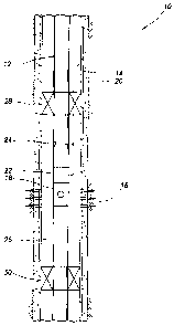
Referring now to FIGS. 2A & B, an enlarged quarter-
sectional view of the packer 28 is representatively
illustrated. In this view, the manner in which a hydraulic
line 32, which has another line 34 therein, extends through
the packer 28 can bEa seen. For example, the line 34 could
be an electrical line or a fiber optic line within the
hydraulic line 32. Note that any number of lines, and any
types of lines, can extend through the packer 28 in keeping
with the principles of the invention.
The packer 28 includes an inner tubular mandrel 36
having threaded connections at each end for interconnection
in the tubing string 12. A tubular outer housing 38 is
reciprocably disposed relative to an annular piston 40. The
piston 40 is sealingly received in a bore 42 of the housing
38, and is positioned radially between the mandrel 36 and
the housing. The piston 40 is sealingly and rigidly
attached to the exterior of the mandrel 36.
An annular seal element 44 is positioned above the
housing 38, between an upper end of the housing and a
downwardly facing shoulder 46 on a connector sub 48. The
connector sub 48 is sealingly and rigidly attached to the
exterior of the mandrel 36.
The lines 32, 34 extend longitudinally through an
opening 50 formed through the connector sub 48. A
compression ferrule-type tubing fitting 52 sealingly secures
the line 32 to the connector sub 48. Another such fitting
56 sealingly secures the line 32 at a lower end of the
piston 40. The lines 32, 34 extend longitudinally through
an opening 60 formed through the piston 40.
To set the packer 28, a pressure differential is
applied longitudinally across a wall 62 of the piston 40.
For example, pressure within the mandrel 36 may be increased
CA 02564190 2006-10-24
WO 2005/116395 PCT/US2005/016972
- 8 -
by applying pressure to the tubing string 12 at the surface.
This pressure is communicated to an upper end of the piston
40 via an opening 64 formed through a sidewall of the
mandrel 36. A lower end of the piston 40 is exposed to
pressure in the annulus 26 about the packer 28 via another
opening 66 formed through a sidewall of the housing 38.
The difference in pressure across the wall 62 of the
piston 40 biases the piston (and mandrel 36) downwardly
relative to the housing 38. Alternatively, it could be
considered that the difference in pressure biases the
housing 38 upwardly relative to the piston 40 (and mandrel
36). Shear pins, shear screws, etc. or other conventional
releasing devices may be used to prevent relative
displacement between the housing 38 and the piston 40 until
a predetermined pressure differential is achieved.
When the housing 38 displaces upwardly relative to the
piston 40, the seal element 44 will be axially compressed
between the upper end of the housing and the shoulder 46.
This axial compression will cause the seal element 44 to
extend radially outward into sealing contact with the
wellbore 14, thereby setting the packer 28. An internally
toothed ratchet device 68 grips the exterior of the piston
40 and prevents the housing 38 from displacing downwardly
once,it has displaced upwardly relative to the piston.
Another compression ferrule-type tubing fitting 54 is
connected to the ring 58. However, instead of securing the
line 32 to the ring 58, the fitting 54 sealingly secures a
tube 70 to the ring. The tube 70 extends downwardly from
the fitting 54 and into the opening 60 in the piston 40.
The tube 70 is sealingly and reciprocably received in the
opening 60.
CA 02564190 2006-10-24
WO 2005/116395 PCT/US2005/016972
- 9 -
The lines 32, 34 extend longitudinally through the tube
70. As the housing 38 displaces upward relative to the
piston 40, the ring 58, fitting 54 and tube 70 can also
displace upward with the housing. However, since the tube
70 is sealed in the piston 40, the tube's wall continues to
isolate pressure on the top of the piston (communicated from
the interior of the mandrel 36 via the opening 64) from
pressure in the opening 60, and from pressure in the annular
space 72 above the ring 58 and radially between the mandrel
36 and the housing 38.
Note that the piston 40 has an outer diameter PD which
is concentric with an inner diameter Pd of the piston. Each
of these diameters PD, Pd is also concentric with inner and
outer diameters Md, MD of the mandrel 36. Similarly, each
of these diameters Pd, Pd, MD, Md is concentric with inner
and outer diameters Hd, HD of the housing 38.
Thus, the packer 28 does not require any of the
mandrel, housing and piston 36, 38, 40 to be eccentric with
respect to any of the others in order for the lines 32, 34
to extend through the packer. Yet, the piston 40 is
provided with a relatively large piston area and the lines
32, 34 are protected within the packer 28, without
restricting flow or access through the mandrel 36.
Referring additionally now to FIG. 3, a quarter-
sectional view of the packer 28 is representatively
illustrated, taken along line 3-3 of FIG. 2B. In this view
it may be seen that the packer 28 can include additional
lines 74,. 76, 78, 80 extending through the wall 62 of the
piston 40. These lines 74, 76, 78, 80 can be any types of
lines, and any number of lines may be used.
Referring additionally now to FIGS. 4A-C, a quarter-
sectional view of the packer 30 is representatively
CA 02564190 2006-10-24
WO 2005/116395 PCT/US2005/016972
- 10 -
illustrated. The packer 30 is similar in many respects to
the packer 28 described above, and so elements shown in
FIGS. 4A-C which are similar to those described above are
indicated using the same reference numbers.
One substantial difference between the packers 28, 30
is that the packer 30 includes slips 82 (only one of which
is visible in FIGS. 4B & C) for anchoring the packer in the
wellbore 14. Another substantial difference is that a
piston 84 of the packer 30 is not rigidly attached to an
inner mandrel 86. Instead, the piston 84 displaces
downwardly relative to the mandrel 86 when the packer 30
sets.
This downward displacement of the piston 84 relative to
the mandrel 86 pushes an upper wedge 88 downward also,
causing the slips 82 to be displaced radially outward by
inclined surfaces on the upper wedge and on a lower wedge 90
at a lower end of the slips. The upper wedge 88 is
prevented from displacing upward by an internally toothed
ratchet 94 once the upper wedge has displaced downwardly
relative to the mandrel 86.
Yet another substantial difference is that the packer
includes an anti-preset device 92 which prevents setting
of the packer until an appropriate pressure level is applied
to an upper side of the piston 84 via the opening 64. Once
25 the pressure level is attained, the device 92 releases and
permits the packer 30 to be set. This prevents external
loads applied to the packer 30 during run-in from causing
the packer to set prematurely.
Note that the packer 30 includes a ring 96 which is
30 somewhat similar to the ring 58 of the packer 28. One or
more shear screws 98 releasably secures the ring 96 in
position. However, when pressure transmitted to the top of
CA 02564190 2006-10-24
WO 2005/116395 PCT/US2005/016972
- 11 -
the piston 84 via the opening 64 exceeds pressure in the
annulus 26 by a predetermined amount, the screws shear and
the ring 96 displaces upward, thereby releasing the anti-
preset device 92.
As with the packer 28, the packer 30 has a concentric
piston 84, mandrel 86 and outer housing 100. The line 32
extends through the piston 84 within the tube 70, which
isolates pressure in the interior of the tubing string 12
(applied to the top of the piston 84 and the exterior of the
tube via the opening 64) from pressure in the annulus 26
(applied to the bottom of the piston and to the interior of
the tube).
Although the above descriptions of the packers 28, 30
have indicated that tubing pressure is used to set the
packers, it will be readily appreciated that other pressure
sources could be used. For example, a propellant could be
used, the packers could alternatively be set mechanically
(such as by manipulation of the tubing string 12), etc.
Furthermore, the packers 28, 30 could be released using a
shear ring, rotation of the tubing string 12, by milling or
cutting, shifting a sleeve, punching a port through the
mandrels 36, 86 and applying pressure to a chamber, etc., or
by any other method.
Of course, a person skilled in the art would, upon a
careful consideration of the above description of
representative embodiments of the invention, readily
appreciate that many modifications, additions,
substitutions, deletibns, and other changes may be made to
these specific embodiments, and such changes are
contemplated by the principles of the present invention.
Accordingly, the foregoing detailed description is to be
clearly understood as being given by way of illustration and
CA 02564190 2006-10-24
WO 2005/116395 PCT/US2005/016972
- 12 -
example only, the spirit and scope of the present invention
being limited solely by the appended claims and their
equivalents.